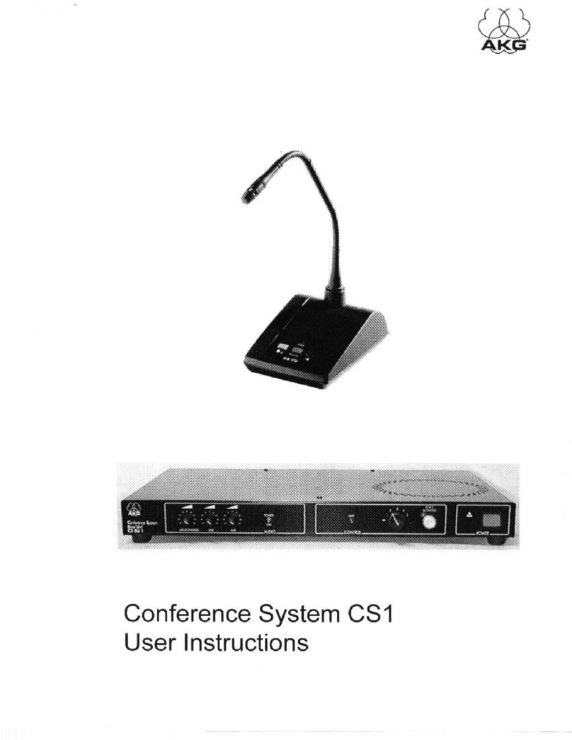
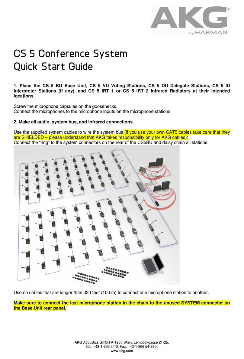
AKG CSX IRS10 User manual

CSX IRS10 Manual V1.1 1 / 32
CSX IRS10
10 Channel Infrared Systen
USER MANUAL

CSX IRS10 Manual V1.1 2 / 32
Please read before using the equipment!
Printed in Hungary
January 2015
Version: 1.1 Contents
CONTENT
1. GENERAL INFORMATION ................................................................................................5
1.1. INTRODUCTION ............................................................................................................... 5
2. CSX IRS10 SYSTEM SERVICES.........................................................................................5
2.1. CORE FUNCTIONS............................................................................................................. 5
2.2. GENERAL SYSTEM CHARACTERISTICS..................................................................................... 6
2.3. CENTRAL UNIT BIR 10...................................................................................................... 8
2.3.1. General introduction............................................................................................ 8
2.3.2. Operation guide................................................................................................... 9
2.3.3. DIP switches....................................................................................................... 10
2.3.4. Technical data CSX BIR10................................................................................... 14
2.3.5. CONNECTORS:.................................................................................................... 15
2.4. INFRARED RADIATORS CSX IRT 3AND IRT 4....................................................................... 16
2.4.1. Technical data: IRT3(spot: +/-17°) ...................................................................... 18
2.4.2. Technical data: IRT4(wide range: +/-60°) ........................................................... 19
2.5. INFRARED RECEIVER UNIT IRR10 ....................................................................................... 21
2.5.1. Menu system screens of IRR10: (Diagram 8.) ..................................................... 24
2.6. SERVICE MENU AND CHANNEL-MNEMONIC SETTINGS .............................................................. 25
2.6.1. Channel assignement......................................................................................... 25
2.6.2. Technical data:................................................................................................... 27
2.7. CHARGING-STORING CASE CSX CU50................................................................................ 29
2.7.1. Technical data.................................................................................................... 30
3. PLACING, CABLING AND SETTING UP THE UNITS OF THE SYSTEM..............31
4. CO-OPERATION WITH CS5 CONFERENCE SYSTEM..............................................32
5. CONFORMITY.....................................................................................................................32

CSX IRS10 Manual V1.1 3 / 32
Safety Instructions
Do not place any containers containing liquid on the device or the powerpack
Do not spill any liquids on the equipment and do not drop any objects through the
ventilation slots in the equipment.
Use the equipment in dry rooms only. Do not expose the equipment to rain or splash
water. Never place objects containing liquids (e.g., vases) on or near the equipment.
There are no user-serviceable parts inside the equipment. Do not attempt to service the
equipment yourself. Refer all servicing to qualified personnel. Opening the chassis for any reason
will void the manufacturer’s warranty.
Before connecting the equipment to power, check that the AC mains voltage stated on the
power supply included with the equipment is identical to the AC mains voltage available where
you will use the equipment. Also check that the power outlet is a standard type with a protective
ground connection. Disconnecting the protective ground lead or using non-standard power plugs
or non-standard power outlets is illegal.
Operate the equipment only with the included or required power supply. Using a different
power supply may cause serious damage to the unit.
If any solid object or liquid penetrates into the equipment, shut down the system
immediately. Disconnect the equipment from power immediately and have the equipment
checked by AKG service personnel.
If you will not use the equipment for a long period of time, disconnect the equipment from
power. Please note that the equipment will not be fully isolated from power when you set the
power switch to OFF.
Disconnect the equipment from power during storms to prevent damage.
Make sure to route power supply cords so that they are not likely to be walked on or
pinched by items placed upon or against them, paying particular attention to cords at plugs,
convenience receptacles, and the points where they exit from the equipment.
To avoid hum or interference, route all audio lines, particularly those connected to
microphone inputs, away from power lines of any type. If you use cable ducts, be sure to use
separate ducts for the audio lines.
Make sure to replace each built-in fuse with a standard fuse of the same type and rating
only. Using any other type of fuse may cause excessive heating and/or a risk of fire.
Never switch more than twenty microphone stations on simultaneously because the
resulting current drain may cause a risk of fire.

CSX IRS10 Manual V1.1 4 / 32
Do not place the equipment near heat sources such as radiators, heating ducts, or
amplifiers, etc. and do not expose it to direct sunlight, excessive dust, moisture, rain, mechanical
vibrations, or shock.
Clean the equipment with a moistened (not wet) cloth only. Be sure to disconnect the
equipment from power before cleaning the equipment! Never use caustic or scouring cleaners or
cleaning agents containing alcohol or solvents since these may damage the enamel and plastic
parts.
Use the equipment for the applications described in this manual only. AKG cannot accept
any liability for damage resulting from improper handling or misuse.
Any changes or modifications to the equipment not expressly approved by the
manufacturer may void the user's authority to operate the equipment.
Environment
When scrapping the equipment, separate the case, circuit boards, and cables, and
dispose of all components in accordance with local waste disposal rules.
The packaging of the equipment is recyclable. Dispose of the packaging in an
appropriate container provided by the local waste collection/recycling entity and observe
all local legislation relating to waste disposal and recycling.
FCC Statement
This device complies with Part 15 of the FCC Rules. Operation is subject to the following two
conditions: (1) this device may not cause harmful interference, and (2) this device must
accept any interference received, including interference that may cause undesired operation.
Changes or modifications not expressly
approved by the party responsible
for compliance could void the
user’s authority to operate the equipment.

CSX IRS10 Manual V1.1 5 / 32
1. GENERAL INFORMATION
1.1. INTRODUCTION
CSX IRS10 digital multichannel infrared system (Diagram 1) is primarliy used in multi-lingual
meetings, conferences and tour guide applications. The CSX IRS10 includes the components CSX
BIR10, CSX IRR10, CSX IRT3, CSX IRT4 units. It can be used as stand alone system, but also in
combination with the CS5 conference system. When using the system in combination with CS5,
the CSX BIR10 is connected in the data ring of the conference system and uses 10 channels to
transmit via the radiators (CSX IRT3 and 4) to an audience equipped with pocket receivers (CSX
IRR10) and headphones (e.g. AKG K15).
It is also possible to feed up to 10 external audio sources directly into the base station CSX
BIR10. This way the system can be used with any other conference system providing analogue
audio channels, any microphone mixer for mobile translation systems, MP3 players or similar for
tour guide systems or any other source (e.g. to provide hearing assistance in movie theatres).
The desired channel can be selected with the aid of the CSX IRR10 channel selector. The
volume can be set with the aid of the volume regulator of the unit. Thanks to the size of the
receiver and infrared signal, the system allows not only free sitting order and mobility during the
meeting, but it also provides protection against unauthorised eavesdropping efforts as well.
To charge the batteries of the CSX IRR10 a charging case CSX CU50 for 50 pieces is offered.
Within a few hours the charging is completed and enables the use for more than 20 hours.
The simple cabling of the system and the mechanical design of the units are advantageous
for both mobile arrangements and fixed installations. Programming the units is technically simple
and the management and the OLED display system of the receivers are ergonomic and fully
compliant with the international standards.
2. CSX IRS10 SYSTEM SERVICES
2.1. CORE FUNCTIONS
The basic components of the CSX IRS10 system of the conference contain a CSX BIR10
controller, CSX IRT3, CSX IRT4 IR radiators, a number of CSX IRR10 pocket receivers and the CS5
PS12 - 48V power supply. When using the system in the CS5 conference loop you can take up to
10 language channels from the system bus, which can then be recorded or distributed from the
RCA socket of BIR10. In case of connecting 10 external analogue channels to the RCA inputs, the
channels can be radiated by the IRT3-4.
The main characteristics of the system are the following:
Digital Transmission with PPM technology
- effective audio and radiation quality control – easy to install
CSX IRS10 Manual V1.1 6 / 32
For CS5 or as standalone system
- works with all kind of analogue inputs
Breakout box for CS5
- feeds signal out of the digital conference ring to external devices
Unlimited expansion of radiators
- for any room size
Low energy technology for receivers
- up to 20 hours operational time with only 2x AA standard rechargeable batteries
2.2. GENERAL SYSTEM CHARACTERISTICS
The core equipment of the system is the central unit CSX BIR 10. All kinds of analogue
audio inputs can be used. The analogue devices are connected through standard connecting
interfaces and levels, with traditional (point-to-point) cabling.
The radiators CSX IRT 3 and CSX IRT 4 are connected to the unit through chain-like (series)
cabling. The infrared radiators communicate with the unit through a 50-ohm coaxial wire.
The infrared radiators have radiation characteristics of an opening angle of +/-17° with a
cone-like start. The axis direction effective ranges of the radiators are either 80m (in the case of
unit IRT3) or 40m (in the case of unit IRT 4 +/-60°). Naturally, the sound reflecting and damping
properties of the room may significantly influence these radiation characteristics.
An important accessory of the system is the charging-storing case CSX CU50, which ensures
the storing and transportability of the 50 infrared receivers and the charging of the 2x1, 4V-
2700mAh NiMH Accumulator inserted into the receivers.
Important notes for the cable-lenghts:
All used system cables (between IRS10 units) have to be shorter then 3m, except 50 ohm
coax from BIR10 to IRT3-4. This point to point length can be up to 100m as maximum.

CSX IRS10 Manual V1.1 7 / 32
Diagram 1: Overview drawing of system IRS 10.
115/230VAC
115/230VAC
1
15/230VAC
1
15/
230V
AC
1
15/
230V
AC
IRT3, IRT4 transmitters
INPUT1-10: Analog 0dBU external sources
48V DC power
CS5 conference ring
CS5 conference system
with BU controller
OUTPUT1-10: Analog 0dBU channels
from Cs5 system bus
IRR10 channel receiver

CSX IRS10 Manual V1.1 8 / 32
2.3. CENTRAL UNIT BIR 10
2.3.1. General introduction
Central unit CSX BIR 10 is the core element of system CSX IRS10 and is required for all
possible configurations. 2 modes are possible:
1. As part of CS5 system – in this mode the unit acts as 10 channel infrared modulator
and/or as breakout box to provide 10 selectable channels of the CS5 data ring to external devices
via 10 RCA connectors on the back panel
2. As stand alone IR system using analogue signals from external devices (modulate them
and send them to the radiators). The external signals are fed in via 10x RCA connectors on the
back panel. These signals will NOT be fed into a CS5 data ring.
4 BNC connectors are used for 4 strings of radiators that are daisy chained. A detailed
description will follow a bit later describing CSX IRT3 and 4.
Diagram 2: Overview sketch of unit BIR 10
1
2
34
5
6

CSX IRS10 Manual V1.1 9 / 32
The following table contains the name and function of operator and display components.
(Diagram 2)
Number Name – function
1 „ON” green LED - indicates the existence of the
power
2 „CS ACTIVE” red LED - indicates the existence of the
connected CS5 conference system
3 „IR ACTIVE” - IR transmitters LEDs on the front panel
are active (IR radiated state)
4,5,6 „IR Transmitter” - IR radiator LEDs
2.3.2. Operation guide
Starting up the operation of CSX BIR 10 – connecting power (diagram 4 – 1 – use only CS5
PS12 power supply) and switching on the unit – is indicated by green LED (diagram 2 - 1).
Inserting the unit into the CS5 data ring and showing an active CS 5 system „CS ACTIVE” LED
(diagram 2 - 2) is noted on of the front panel. The 3rd LED (diagram 2 - 3) “IR ACTIVE” is on
continuously to detect the IR control beam out of the window.
CSX BIR10 also contains a 10-channel analogue RCA input section (diagram 4 - 6), and a 10-
channel analogue RCA output section (diagram 4 - 5) (see the block scheme which is presented in
Diagram 3 in the previous page). Depending on the DIP configuration, the input channels are
forwarded to channels 1-10 of the PPM modulator of the unit to drive the IR radiators as well as
the diodes on front panel (to enable IR monitoring in technician room).
INPUT sensitivity can be regulated using trimmers on the back (Diagram 4 - 6).
When inserting the unit BIR 10 in the conference line (Diagram 4 - 3,4) CS 5, up to 10
channels can be taken out from the system channels. These channels are decoded and put out to
the RCA analogue outputs as standard 0dBU level. (Diagram 4 - 5)
One can also mix inputs from CS5 and/or external sources either using patch cables from
output to input RCA to use CS5 channels and feeding external sources to the input RCA board as
well. That way you can fine tune all input levels using the input potis next to the input RCA, or
using the right DIP switch configuration described further down.

CSX IRS10 Manual V1.1 10 / 32
BIR10 base board
Cs5 conference system
Rj45
4xBNC IR OUT
DC IN
10xRCA IN
10xRCA OUT analog
IRM10 IR modulator
Diagram 3 - Block scheme of the analogue part of central unit CSX BIR10
2.3.3. DIP switches
DIP switches are located at the back plane. Functions are included in the following table.
Dip switch position:
UP 1
The dip switch with the higher number overrules the dip
switches with a lower number
DOWN 0
Dip switches 2-7 select channels according to dip switch 1
don't care x
DIP 1
(floor) DIP 2 DIP 3 DIP 4 DIP 5 DIP 6 DIP 7 DIP 8 selected channels
from CS5 ring to IR
0 0 0 0 0 0 0 0 0-9
1 0 0 0 0 0 0 0 1-10
0 1 0 0 0 0 0 0 10-19
1 1 0 0 0 0 0 0 11-20
0 x 1 0 0 0 0 0 20-29
1 x 1 0 0 0 0 0 21-30
0 x x 1 0 0 0 0 30-39
1 x x 1 0 0 0 0 31-40
0 x x x 1 0 0 0 40-49
1 x x x 1 0 0 0 41-50
0 x x x x 1 0 0 50-59
1 x x x x 1 0 0 61-60
x x x x x x 1 0 54-63
DIP 1 DIP 2 DIP 3 DIP 4 DIP 5 DIP 6 DIP 7 DIP 8 select audio source
for the IR modulator
x x x x x x x 0 ring/FPGA (according
to DIP 1)
x x x x x x x 1 Analog audio
from backplane

CSX IRS10 Manual V1.1 11 / 32
2.3.4. Series Production
Routing R1 - Conference Only
DIP 1 DIP 2 DIP 3 DIP 4 DIP 5 DIP 6 DIP 7 DIP 8 IR output channel 1-10
from CS 5 ring channel #
IR output channel
from ext. input # Routing
x 0 0 1 0 0 0 0 0-9 NONE R1
x001 0 0 0 1 1-10 NONE R1
x0 0 1 0 0 1 0 10-19 NONE R1
x001 0 0 1 1 11-20 NONE R1
x0 0 1 0 1 0 0 20-29 NONE R1
x001 0 1 0 1 21-30 NONE R1
x0 0 1 0 1 1 0 30-39 NONE R1
x001 0 1 1 1 31-40 NONE R1
x0 0 1 1 0 0 0 40-49 NONE R1
x001 1 0 0 1 41-50 NONE R1
x0 0 1 1 0 1 0 50-59 NONE R1
x001 1 0 1 1 51-60 NONE R1
x001 1 1 0 054-63 NONE R1
Routing R2 - 50/50 External lower bank
DIP 1 DIP 2 DIP 3 DIP 4 DIP 5 DIP 6 DIP 7 DIP 8 IR output channel 6-10
from CS 5 ring channel #
IR output channel
1-5 from ext. input # Routing
x 0 1 0 0 0 0 0 0-4 1-5 R2
x01 0 0 0 0 1 1-5 1-5 R2
x0 1 0 0 0 1 0 10-14 1-5 R2
x01 0 0 0 1 1 11-15 1-5 R2
x0 1 0 0 1 0 0 20-24 1-5 R2
x01 0 0 1 0 1 21-25 1-5 R2
x0 1 0 0 1 1 0 30-34 1-5 R2
x01 0 0 1 1 1 31-35 1-5 R2
x0 1 0 1 0 0 0 40-44 1-5 R2
x01 0 1 0 0 1 41-45 1-5 R2
x0 1 0 1 0 1 0 50-54 1-5 R2
x01 0 1 0 1 1 51-55 1-5 R2
x01 0 1 1 0 059-63 1-5 R2

CSX IRS10 Manual V1.1 12 / 32
Routing R3 - 50/50 External upper bank
DIP 1 DIP 2 DIP 3 DIP 4 DIP 5 DIP 6 DIP 7 DIP 8 IR output channel 1-5
from CS 5 ring channel #
IR output channel
6-10 from ext. input # Routing
x 0 1 1 0 0 0 0 0-4 6-10 R3
x01 1 0 0 0 1 1-5 6-10 R3
x0 1 1 0 0 1 0 10-14 6-10 R3
x01 1 0 0 1 1 11-15 6-10 R3
x0 1 1 0 1 0 0 20-24 6-10 R3
x01 1 0 1 0 1 21-25 6-10 R3
x0 1 1 0 1 1 0 30-34 6-10 R3
x01 1 0 1 1 1 31-35 6-10 R3
x0 1 1 1 0 0 0 40-44 6-10 R3
x01 1 1 0 0 1 41-45 6-10 R3
x0 1 1 1 0 1 0 50-54 6-10 R3
x01 1 1 0 1 1 51-55 6-10 R3
x01 1 1 1 0 059-63 6-10 R3
Routing R4 – Talkback
DIP 1 DIP 2 DIP 3 DIP 4 DIP 5 DIP 6 DIP 7 DIP 8 IR output channel 1-9
from CS 5 ring channel #
IR output channel
10 from ext. input # Routing
x 1 0 0 0 0 0 0 0-8 10 R4
x1 0 00 0 0 1 1-9 10 R4
x1 0 0 0 0 1 0 10-18 10 R4
x1 0 00 0 1 1 11-19 10 R4
x1 0 0 0 1 0 0 20-28 10 R4
x1 0 00 1 0 1 21-29 10 R4
x1 0 0 0 1 1 0 30-38 10 R4
x1 0 00 1 1 1 31-39 10 R4
x1 0 0 1 0 0 0 40-48 10 R4
x1 0 01 0 0 1 41-49 10 R4
x1 0 0 1 0 1 0 50-58 10 R4
x1 0 01 0 1 1 51-59 10 R4
x1 0 01 1 0 055-63 10 R4

CSX IRS10 Manual V1.1 13 / 32
Routing R5 – 8/2
DIP 1 DIP 2 DIP 3 DIP 4 DIP 5 DIP 6 DIP 7 DIP 8 IR output channel 3-10
from CS 5 ring channel #
IR output channel
1-2 from ext. input # Routing
x 1 0 1 0 0 0 0 0-7 1-2 R5
x1 0 1 0 0 0 1 1-8 1-2 R5
x1 0 1 0 0 1 0 10-17 1-2 R5
x1 0 1 0 0 1 1 11-18 1-2 R5
x1 0 1 0 1 0 0 20-27 1-2 R5
x1 0 1 0 1 0 1 21-28 1-2 R5
x1 0 1 0 1 1 0 30-37 1-2 R5
x1 0 1 0 1 1 1 31-38 1-2 R5
x1 0 1 1 0 0 0 40-47 1-2 R5
x1 0 1 1 0 0 1 41-48 1-2 R5
x1 0 1 1 0 1 0 50-57 1-2 R5
x1 0 1 1 0 1 1 51-58 1-2 R5
x1 0 1 1 1 0 056-63 1-2 R5
Routing R6 – 2/8
DIP 1 DIP 2 DIP 3 DIP 4 DIP 5 DIP 6 DIP 7 DIP 8 IR output channel 9-10
from CS 5 ring channel #
IR output channel
1-8 from ext. input # Routing
x 1 1 0 0 0 0 0 0-1 1-8 R6
x1 1 0 0 0 0 1 1-2 1-8 R6
x1 1 0 0 0 1 0 10-11 1-8 R6
x1 1 0 0 0 1 1 11-12 1-8 R6
x1 1 0 0 1 0 0 20-21 1-8 R6
x1 1 0 0 1 0 1 21-22 1-8 R6
x1 1 0 0 1 1 0 30-31 1-8 R6
x1 1 0 0 1 1 1 31-32 1-8 R6
x1 1 0 1 0 0 0 40-41 1-8 R6
x1 1 0 1 0 0 1 41-42 1-8 R6
x1 1 0 1 0 1 0 50-51 1-8 R6
x1 1 0 1 0 1 1 51-52 1-8 R6
x1 1 0 1 1 0 0 60-61 1-8 R6
x1 1 0 1 1 0 1 61-62 1-8 R6

CSX IRS10 Manual V1.1 14 / 32
Routing R7 – External only
DIP 1 DIP 2 DIP 3 DIP 4 DIP 5 DIP 6 DIP 7 DIP 8 IR output channel from
CS 5 ring channel #
IR output channel
1-10 from ext. input # Routing
x 1 1 1 0000NONE 1-10 R7
Routing R8 – Floor/9
DIP 1 DIP 2 DIP 3 DIP 4 DIP 5 DIP 6 DIP 7 DIP 8 IR output channel 10
from CS 5 ring channel #
IR output channel
1-9 from ext. input # Routing
x 0 0 0 00000 1-9 R8
2.3.5. Technical data CSX BIR10
Height : 44 mm (1 HE)
Width : 482 mm (19”)
Depth (with connectors) : 108 mm
Mass : 1450 g
Parameter Nominal Unit
DC parameters
Power voltage (Use CS5 PS12 only) 48 V
Power consumption
W
Data Connectors
Infra Out 50Ω TTL level output
System CS5 compatible
Audio input connectors
INPUT 1 – INPUT 10 level 0 dBu
INPUT impedance 20 kOhm
Audio output connectors
OUTPUT 1 - OUTPUT 10 level 0 dBu
Load impedance for outputs 1 kOhm
Relation of signal-noise at the outputs 90 dB

CSX IRS10 Manual V1.1 15 / 32
Frequency range (-3dB) 20 - 20000 Hz
LED States
Green Power Supply
Yellow CS Active
Red IR Active
2.3.6. CONNECTORS:
SYSTEM:
RJ 45 socket:
Pin
Function
1
Transmit Data +
2
Transmit Data
-
3
Receive Data+
4
DC 48 V
5
DC 48 V
6
Receive Data
-
7
GND
8
GND
Coaxial cable connector:
INFRA OUT
BNC (50 ohm):
Pin
Function
1
PPM data signal
2
GND
12
3
45
678
9

CSX IRS10 Manual V1.1 16 / 32
Diagram 4
The following table contains the name and function of those operator and display
components and connectors of unit BIR 10. (Diagram 4)
Number Name – function
1 DC adapter in (48V) – CS5PS12
2 Config. DIP switch
3,4 CS5 system integration (RJ45)
5 10 channels analogue OUTs (RCA asymmetrical)
7 10 channels analogue Ins (RCA asymmetrical)
6 Trimmers to adjust INPUT sensitivity
8,9 BNC out to drive IR radiators (50 ohm coax.)
2.4. INFRARED RADIATORS CSX IRT 3AND IRT 4
The infrared radiators are connected to the CSX BIR10 output marked „INFRA OUT” with 50
Ohm coaxial cabling and serial concatenation. The PPM system modulated time-multiplex
outputs of the central unit can drive an arbitrary number of radiators, however, the inputs and
outputs of the radiators („IN” and „OUT”) cannot be exchanged. A connector marked „IN” is an
input for receiving the signals, while a connector marked „OUT” is for driving the next radiator
concatenated serially. The difference between units IRT 3 and IRT 4 is in their radiated angle:
IRT3: +/-17°
IRT4: +/-60°
The infrared radiators need mains power supply, for this reason it is necessary to build out
a mains connector in the vicinity of each radiator.
Important! The infrared radiators do not have a mains switch. Therefore in the case of fixed
installation it is necessary to build out a power network, protected with a small circuit breaker
that may be switched off from the technical room.
The infrared radiators include the holding frame needed for mounting it to the sidewall or
the ceiling; with the aid of which it is possible to install the radiators in an axis oriented direction.
The layout of the indicating and connecting devices of the infrared radiators is shown on
Diagram 1.

CSX IRS10 Manual V1.1 17 / 32
1
2
3
6
5
4
Diagram 5 – Overview drawing of infrared radiators IRT3, IRT4
The following table contains the legend of Diagram 5.
Number
3 „POWER” green LED - indicates the existence of the
power
4 „OPERATE” red LED - indicates the control signal
existence at the INPUT
1 „IN” - input coaxial connector (BNC)
2 „OUT” - output coaxial connector (BNC)

CSX IRS10 Manual V1.1 18 / 32
2.4.1. Technical data: IRT3 (spot: +/-17°)
Technical data
Height 260 mm
Width 280 mm
Depth 70 mm
Mass 4 kg
Electrical parameters
Power supply (wide range)
200-240 volts50/60 Hz 1.5 A
to
100-120 volts 50/60 Hz 3.15A
Control Input, Output level and impedance 5V TTL /
50 ohms*
Wavelength 870 nm
Radiated power 12,5 W
Angle of half intensity +/-17°
Effective distance 65 m
Power consumption (AC) 100 watts
Switch ON transient Max: 2,5 A
LED Status
Green Power Supply
Red Control Signal

CSX IRS10 Manual V1.1 19 / 32
2.4.2. Technical data: IRT4 (wide range: +/-60°)
Technical data
Height 260 mm
Width 280 mm
Depth 70 mm
Mass 4 kg
Electrical parameters
Power supply (wide range)
200-240 volts 50/60 Hz 1.5 A
to
100-120 volts 50/60 Hz 3.15 A
Control Input, Output level and impedance 5V TTL /
50 ohms*
Wavelength 870 nm
Radiated power 11,4 watts
Angle of half intensity +/-60°
Effective distance 35 m
Power consumption (AC) 100 watts
Switch ON transient Max: 2,5 A
LED States
Green Power Supply
Red Control Signal

CSX IRS10 Manual V1.1 20 / 32
65m
+-17
+-60
35m
Radiated charasteristics and effective distances IRT3, IRT4
Table of contents
Other AKG Conference System manuals