Oval EL2310-0DE Series User manual

MODEL : EL2310-0DE□□□
Applicable Flowmeter: Ultrasonic Flowmeter for Liquid
Psonic-L4
SMART COMMUNICATION UNIT
For the installation of application software "LinkTop" and the interface
driver, refer to Ins. No. E-020IMC "Smart Communication Unit MODEL:
EL2310 Software Installation Procedure Manual".
Ins. No. E-026-3-E
1

E-026-3-E
2
CONTENTS
1. SMART COMMUNICATION UNIT ............................................................................... 4
1.1 General .................................................................................................................................4
2. BEFORE YOU BEGIN................................................................................................... 4
2.1 Inspection upon Receipt ......................................................................................................4
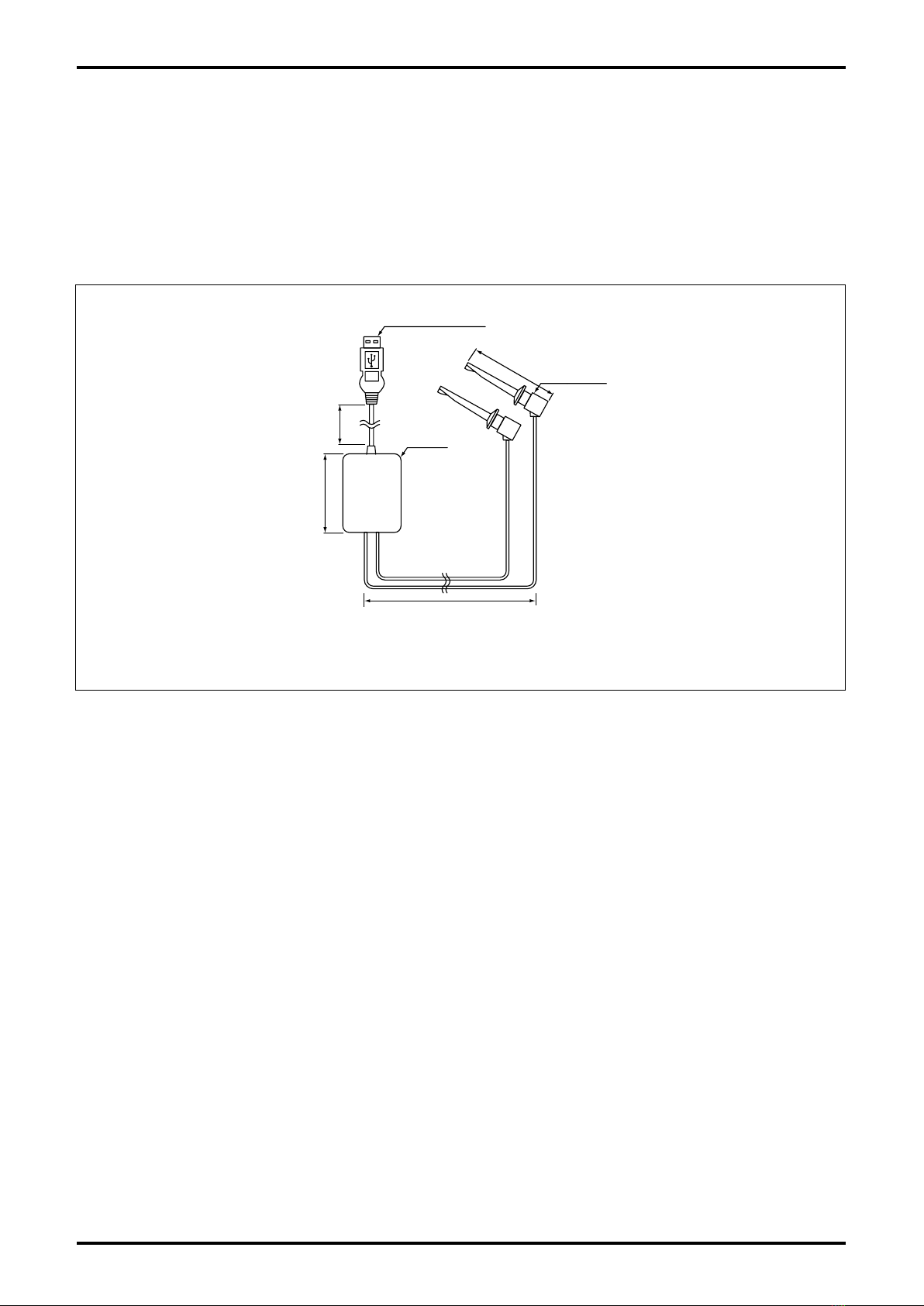
2.2 Hookup with Associated Equipment and Devices ...............................................................5
2.3 Communication Interface .....................................................................................................6
3. LinkTop OPERATION ................................................................................................... 7
3.1 LinkTop Screen.....................................................................................................................7
3.2 Starting LinkTop and Connections.......................................................................................8
3.2.1 Starting LinkTop ............................................................................................................................ 8
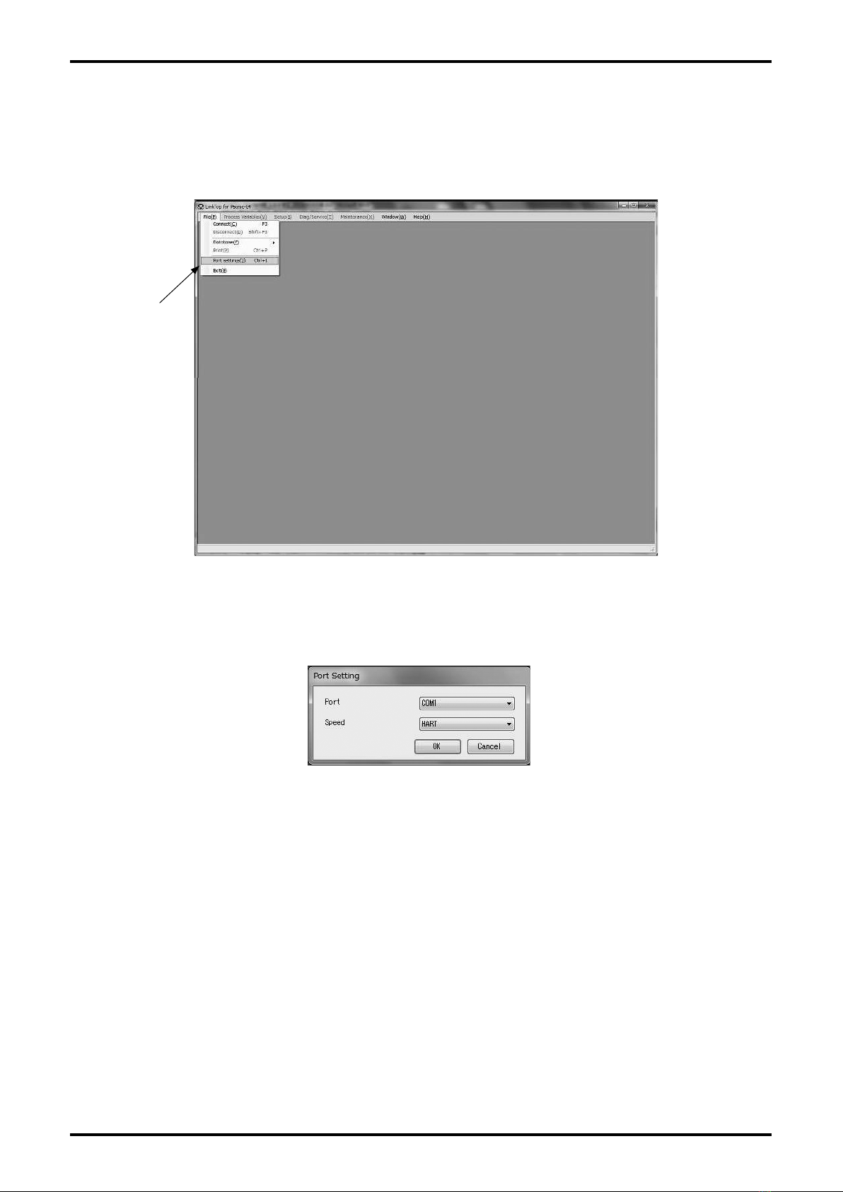
3.2.2 Port Setting ................................................................................................................................... 9
3.2.3 Connection.................................................................................................................................. 11
3.3 Terminating the Connection ...............................................................................................13
3.4 Terminating LinkTop ...........................................................................................................14
3.5 Menu: Process Variables (processing values display)........................................................15
3.5.1 View fld dev vars (processing values measurement) .................................................................. 16
3.5.2 Chart and Recording (chart display and logging) ....................................................................... 17
3.5.3 Write protect (write status display of transmitter) ....................................................................... 20
3.6 Menu: Setup (settings) .......................................................................................................21
3.6.1 Diameter inside (internal diameter of measuring tube) ............................................................... 22
3.6.2 Fld dev vars (transmitter variable)............................................................................................... 22
3.6.2.1 Flow (parameter setting related to flow rate) ........................................................................22
3.6.2.2 Fluid (parameter setting related to fluid) ............................................................................... 24
3.6.3 Outputs (output setting) .............................................................................................................. 26
3.6.3.1 Pulse output (pulse output setting) .......................................................................................26
3.6.3.2 Status output (status output setting) .................................................................................... 27
3.6.4 Device information (transmitter information setting) ................................................................... 29
3.7 Menu: Diag / Service (check / adjustment) ........................................................................31
3.7.1 Loop Test (loop test)....................................................................................................................32
3.7.1.1 Fix Analog (analog output loop test) ..................................................................................... 32
3.7.1.2 Fix Pulse (pulse output loop test).......................................................................................... 34
3.7.1.3 Fix Flow (simulated flow rate loop test) ................................................................................ 35
3.7.2 Calibration (transmitter's adjustment function)........................................................................... 37
3.7.2.1 Auto zero (auto zero point adjustment)................................................................................. 37
3.7.2.2 Init AGC (sensitivity adjustment) ........................................................................................... 39
3.7.3 Trim Analog (analog output adjustment) ..................................................................................... 41
3.7.4 Totalizer cntrl (cumulative total control) ...................................................................................... 44

E-026-3-E
3
3.8 Menu: Maintenance (maintenance) ....................................................................................45
3.8.1 Device reset (transmitter reset) ...................................................................................................46
3.9 Menu: Window (window) ....................................................................................................47
3.10 Menu: File (file) .................................................................................................................49
3.10.1 Database................................................................................................................................... 49
3.10.1.1 Opening Files ...................................................................................................................... 49
3.10.1.2 Saving Files......................................................................................................................... 50
3.10.1.3 Deleting Files....................................................................................................................... 51
3.10.1.4 Downloading ....................................................................................................................... 52
3.10.2 Printing...................................................................................................................................... 55
3.11 Troubleshooting................................................................................................................57
3.11.1 If There is No Response............................................................................................................57
3.11.2 If It is Not Possible to Connect to the Flowmeter ..................................................................... 57
3.11.3 Input Errors ............................................................................................................................... 58
3.11.4 Error, Status Display List........................................................................................................... 59
4. PRODUCT CODE EXPLANATION ............................................................................. 60
5. GENERAL SPECIFICATIONS..................................................................................... 61
This manual uses the precaution words "NOTE", "CAUTION", and "WARNING" as explained
below:
NOTE: Notes are separated from the general text to bring the user's attention to
important information.
CAUTION: Caution statements inform the user of hazards or unsafe practices which could
result in minor personal injury or product/property damage.
WARNING: Warning statements inform the user of hazards or unsafe practices which could
result in severe personal injury or death.

E-026-3-E
4
NOTE: For the installation of the application software "LinkTop®" and the interface driver software (*),
refer to "Installation Procedure Manual".
*: The driver software in the CD-ROM is intended for an application of Bell202 Communication
Interface for OVAL Smart Communication Unit EL2310.
LinkTop
®
for Psonic-L4
®
Instruction Manual 1
(This manual)
Instruction Manual 2
(Software Installation Procedure Manual)
CD-ROM
(Application software LinkTop®)
1
Ins. No. E-020IMC-1-E
MODEL : EL2310
SMART COMMUNICATION UNIT
SOFTWARE INSTALLATION
PROCEDURE MANUAL
Communication interface
(in case of product with interface)
(for Bell202 communication Fig. 2-2)
MODEL : EL2310-0DE□□□
Applicable Flowmeter: Ultrasonic Flowmeter for Liquid
Psonic-L4
SMART COMMUNICATION UNIT
For the installation of application software "LinkTop" and the interface
driver, refer to Ins. No. E-020IMC "Smart Communication Unit MODEL:
EL2310 Software Installation Procedure Manual".
Ins. No.
E-026-1-E
1
1. SMART COMMUNICATION UNIT
1.1 General
Described in this manual are the operating instructions to use the application software LinkTop®of the
Smart Communication Unit which operates in the Microsoft operating system Windows®environment.
LinkTop®is a communication terminal designed for use in combination with a personal computer
(hereinafter referred to as PC) and any one of the OVAL ultrasonic flowmeters to set up, alter, adjust, or
read out parameters and variables, through interactive communications, either on-site or from remote
locations.
Using a Windows®PC at hand, it is possible to monitor multiple windows on its screen.
It is necessary to install the application software LinkTop®in your PC before connecting the communica-
tion interface (*) between the PC and the flowmeter.
NOTE: In case of Bell202 communication: Bell202 communication interface of OVAL smart
communication unit EL2310 is necessary.
2. BEFORE YOU BEGIN
2.1 Inspection upon Receipt
Be sure you have the following items.
Open the product package and make sure you have all the components required.

E-026-3-E
5
The receiving instrument in this figure requires a load resistance 250
Ωmin. Its upper limit depends on the
specification of the transmitter in use.
If the receiving instrument does not have a built-in RL, an external RLneeds to be connected in series.
Relay terminal block
Fig. 2-1
LINE/+
NEUT/-
+ 4 to 20mADC
−
OVAL ultrasonic flowmeter Receiving instrument
(load resistance RLbuilt-in)
RL
Power
supply
LINE/+
NEUT/−
+
−
Probe
Polarity observation is not required.
Connect the probes across + and - terminals
of analog output.
Connected
point
Bell202 communication
interface
Flowmeter
transmitter
2.2 Hookup with Associated Equipment and Devices
Equipment set-up with associated equipment and devices is shown in Fig. 2-1. (Prepare a PC by yourself.)
Application software
(LinkTop®)
- Procedure of connection -
(1) Connect the cables as shown in Fig. 2-1.
(2) Turn ON the power supply of PC and activate LinkTop for Psonic-L4.
(3) Turn ON the power supply of flowmeter.
* Before connecting the communication cable to the flowmeter transmitter, turn OFF the power supply of
flowmeter.
NOTE: In Fig. 2-1, the customer is to supply a PC that meets the following requirements:
¯OS: Windows XP, Windows Vista, Windows 7 to 10
¯RAM: 256MB or larger
¯Hard disk: 10MB or larger free space
¯USB port that is suitable for connecting to the communication interface to be used shall
be provided. A USB port is required when using Bell202 communication interface for OVAL
Smart Communication Unit EL2310.

E-026-3-E
6
Unit: mm
Probe
USB connector
Body
Cable length from probe
Approx. 500
Cable length from
connector
Approx. 1000
50
(60)
Fig. 2-2
2.3 Communication Interface
A signal transmitter is provided for the communication signal conversion between the external serial port
(COM port) of the PC and the flowmeter.
When using Bell202 communication, the Bell202 communication interface for OVAL smart communication
unit EL2310 shall be used. The signal transmitter consists of the components shown in Fig. 2-2.

E-026-3-E
7
3. LinkTop OPERATION
3.1 LinkTop Screen
(1) Fig. 3-1 shows what the LinkTop window looks like.
Fig. 3-1
Menu
Communication
status display bar
Title bar
Message
box field
(2) "Communication status display bar" displays the communication status of PC and flowmeter. The
description on "communication status display bar" is shown in the table below.
Display item Details
SEND At communications (when sending data)
RECV WAIT At communications (when waiting for receiving data)
IDLE When communications are interrupted
CLOSE When communications are disconnected
(3) The overview of each menu is shown in the table below.
Display item Details
File Setting of communication connection and construction of database
(refer to section 3)
Process Variables Checks the measurement status with numeric values (refer to section
3.5)
Setup Sets the transmitter parameter(refer to section 3.6)
Diag / Service Check and adjustment of transmitter (refer to section 3.7)
Maintenance Reset of transmitter (refer to section 3.8)
Window Arrays displayed windows (refer to section 3.9)

E-026-3-E
8
3.2 Starting LinkTop and Connections
3.2.1 Starting LinkTop
(1) To initiate LinkTop, click "Start" at the bottom left of the PC screen, and then click "LinkTop for
Psonic-L4 (E) Ver1.0.0" in "Program".
(2) The following window (Fig. 3-2) will be displayed and it is possible to verify the version of the
software.
Fig. 3-2
(3) After the window shown in Fig. 3-2 is displayed for a few seconds, the main window (Fig. 3-3) will be
displayed.
Fig. 3-3

E-026-3-E
9
3.2.2 Port Setting
It is possible to change the setting of serial port of PC.
(1) Click "File (F)" from the menu, and then click on "Port Setting (I) Ctrl+I".
Fig. 3-4
(2) The following window (Fig. 3-5) will be displayed. Here, select the serial port of PC.
Fig. 3-5
Click here.

E-026-3-E
10
(3) Click the arrow on right side as shown in Fig. 3-6, and select the port for which connection is
changed from the drop-down list.
It is possible to check whether the port is connected or not with the device manager screen shown in
Fig. 3-7.
Fig. 3-6
Fig. 3-7
(4) After the selection is completed, click "OK" button. After clicking the button, the value will be
changed to the setting value you select and the window will disappear.
If you want to cancel the setting, click "Cancel" button.
(5) The standard setting is "COM1".
* When USB serial port is used, select "COM (port number) (USB)".
* When USB serial port is used, set up the included driver preliminarily and use it in connectable status.
(6) For the setting of communication speed, select "HART".

E-026-3-E
11
Fig. 3-8
Fig. 3-9
3.2.3 Connection
(1) Click "File (F)" from the menu, and then click on "Connect (C) F3".
Click here.
(2) The message box (Fig. 3-9) will be displayed. By clicking "OK" button, the connection will be started.
By clicking "Cancel" button, the connection operation will be cancelled.
The polling address is set to "0" when the product is shipped from factory.

E-026-3-E
12
Fig. 3-10
(3) Click "OK" button in the message box to start the connection. Then, the following window (Fig. 3-10)
will be displayed. It is possible to check the connection status with the progress bar in the center of
window.
Fig. 3-12
Fig. 3-11
The display of "communication status display bar" switches between "SEND" and "RECV WAIT". By
clicking "Cancel" button, the connection will be cancelled.
(4) If the connection is completed, the following message box (Fig. 3-11) will be displayed. Click "OK"
button.
(5) When the connection is completed, some functions of the menu will become selectable (color of
characters will change to black) as shown in Fig. 3-12.

E-026-3-E
13
3.3 Terminating the Connection
To terminate connection between the flowmeter transmitter and LinkTop, follow the procedure given
below:
(1) Click "File (F)" from the menu, and then click on "Disconnect (D) Shift+F3".
(2) The message box (Fig. 3-14) will be displayed. By clicking "OK" button, the connection between
flowmeter and LinkTop will be terminated.
By clicking "Cancel" button, the connection termination operation will be cancelled.
Fig. 3-13
Fig. 3-14
Fig. 3-15
(3) When connection is terminated, some functions of the menu become inactive (characters will change
to white) as shown in Fig. 3-15.
Click here.

E-026-3-E
14
(2) The message box (Fig. 3-17) will be displayed. To exit LinkTop, click "OK" button. Click "OK"
to confirm and the application software window will disappear from the desktop. To abort the
terminating process, click on "Cancel" button.
Fig. 3-16
Fig. 3-17
3.4 Terminating LinkTop
(1) To exit LinkTop, click "File (F)" from the menu and select "Exit (E)" or click "Close" button in the upper
right of the screen.
Click here.

E-026-3-E
15
Fig. 3-18
3.5 Menu: Process Variables (processing values display)
The "Process Variables" menu can be used to confirm process value of flowmeter (instantaneous flow
rate, flow velocity, cumulative total in positive direction, cumulative total in opposite direction, analog
output, Gain1 to 4), chart display, logging, and status of write protect.
Fig. 3-18 shows what the actual screen looks like.

E-026-3-E
16
Fig. 3-19
3.5.1 View fld dev vars (processing values measurement)
(1) Click "Process Variables (V)" from the menu in the upper prat of the screen, and then click on "View
fld dev vars".
(2) The following window (Fig. 3-19) will be displayed.
"Flow rate" ... instantaneous flow rate
"Flow velocity" ... flow velocity
"Forward totalizer" ... cumulative total (positive direction)
"Backward totalizer" ... cumulative total (opposite direction)
"Analog output" ... analog % flow rate
"Gain 1" ... gain value (pass 1)
"Gain 2" ... gain value (pass 2)
"Gain 3" ... gain value (pass 3)
"Gain 4" ... gain value (pass 4)
"Reynolds number" ... Reynolds number
(3) If there is a problem with the flowmeter transmitter, then an error message will be displayed in the
window under the process value measurement window. For details, refer to section 3.11.4 "Error,
Status Display List".
(4) To exit the process value measurement window, click "Cancel" button.

E-026-3-E
17
3.5.2 Chart and Recording (chart display and logging)
Display of flow rate, flow velocity, gain value of sensor as well as data logging can be carried out.
(1) Click "Chart and Recording" from the menu in the upper part of the screen, and select "Active", then
a tool bar as shown in Fig. 3-20 will be displayed underneath the menu.
Fig. 3-20
Fig. 3-21
(2) Click the button on the tool bar or "Chart and Recording" - "Interval" from the menu, then the
window shown in Fig. 3-21 will be displayed, enabling setting of update interval of chart display and
logging interval.
Select the preferred interval from "1 Second", "3 Second", "5 Second", "10 Second", "30 Second",
"1 Minute", "5 Minutes", "10 Minutes", and "1 Hour" and click "OK" button.

E-026-3-E
18
(3) Click the button on the tool bar or "Chart and Recording" - "Chart" - "Percent Flow" from the
menu, then the window shown in Fig. 3-22 will be displayed, enabling chart display of percent flow.
When changing the scale of the vertical axis, enter the preferred values to "Max" and "Min" in "Scale",
then click "OK" button.
Fig. 3-22
(4) A chart is drawn at the intervals of update set in (2).
Fig. 3-23

E-026-3-E
19
(5) To hide the chart, click the button on the tool bar or "Chart and Recording" - "Chart" - "Percent
Flow" from the menu.
(6) Similarly, by clicking the button on the tool bar or "Chart and Recording" - "Chart" - "Flow Rate"
from the menu, instantaneous flow rate can be shown or hidden. If you click the button on the tool
bar or "Chart and Recording" - "Chart" - "Flow Velocity" from the menu, the flow velocity chart can be
shown or hidden as well. The gain value (passes 1 to 4) and Reynolds number are operated in a same
way.
(7) If you click the button on the tool bar or "Chart and Recording" - "Recording" - "Start" from the
menu, the following dialog box (Fig. 3-24) will be displayed. Select the disk and folder to create a file,
enter a file name, and click "Save (S)" button.
A CSV file is created and data logging begins.
Fig. 3-24
(8) If you click the button on the tool bar or "Chart and Recording" - "Recording" - "Stop" from the
menu, the logging will stop (terminating the writing process on the file) and the file will be completed.
Then the following message box (Fig. 3-25) will be displayed. Click "OK" button.
Fig. 3-25

E-026-3-E
20
(9) The content of the log file when logging interval is set to "5 Seconds" is as shown in Fig. 3-26.
Fig. 3-26
Date Percent flow Flow rate Flow velocity Gain 3 Gain 4Gain 2Gain 1
Reynolds number
(10) If you click the button on the tool bar or "Chart and Recording" - "Active" from the menu, chart
display and data logging will be terminated.
3.5.3 Write protect (write status display of transmitter)
Whether the parameter of transmitter can be changed or not is displayed.
(1) Click "Process Variables(V)" in the upper part of the screen, and then click on "Write protect". Then,
the following window (Fig. 3-27) will be displayed.
"Write protect" shows whether parameter change of the transmitter is available or not.
Mode Detail SW (S1-LCK) setting
Not write protected Enables changing and setting parameters. OFF
Write protected Disables changing and setting parameters. ON
NOTE: Selecting the above mode is available by changing switches S1-LCK on the CPU board
of the flowmeter transmitter.
(2) To exit this procedure, click "Cancel" button.
Fig. 3-27
Table of contents
Other Oval Conference System manuals