oventrop Regusol DN 25 User manual

Premium Armaturen + Systeme
„Regusol“ DN 25
Übergabestation mit Regler
Technische Hinweise
Wichtige Informationen zum Wechsel / Anschluss
von Reglern und drehzahlgeregelten Hocheffizienz-
pumpen
Zusätzlich zum Spannungsversorgungskabel (230V)
benötigen drehzahlgeregelte Hocheffizienzpumpen ein
separates abel zur Übertragung des Steuersignales.
Gebräuchliche Steuersignale sind 0-10 Volt und Puls-
weitenmodulation (PWM) in proportionaler und inver-
tierter Form.
Die erforderliche Signalart ist der beiliegenden Bedie-
nungsanleitung der jeweiligen Pumpe zu entnehmen!
Sind die Steuersignale von Regelung und Pumpe
nicht aufeinander abgestimmt, ist ein Betrieb nicht
möglich.
Zur Vermeidung von Störungen und schweren Schäden
an Anlagen mit drehzahlgeregelten Hocheffizienzpum-
pen ist Folgendes zu beachten:
– Austausch der Pumpe nur gegen eine Pumpe mit
identischem Steuersignal!
– Austausch eines Reglers nur gegen einen Regler
mit identischem Steuersignal!
– Durch ombination von Pumpe und Regler mit un-
terschiedlichen Steuersignalen ist die Betriebssi-
cherheit nicht gewährleistet, Anlagenschäden und
Gesundheitsschäden sind nicht auszuschließen!
– Im Rahmen der ersten Inbetriebnahme als auch
nach Austausch der Pumpe oder des Reglers ist
folgender Funktionstest durchzuführen:
– Pumpe im Handmenü (Relaistest) "EIN" schalten –
die Pumpe muss nun laufen.
–Anschließend die Pumpe im Handmenü "AUS"
schalten, die Pumpe darf nun nicht mehr laufen.
–Elektroarbeiten dürfen nur von qualifiziertem Elek-
tro-Fachpersonal durchgeführt werden.
– Vor Arbeiten an elektrischen omponenten sind
diese spannungsfrei zu schalten.
– alle Arbeiten und Einstellungen im Rahmen des
Austausches dürfen, wenn nicht ausdrücklich anders
erwähnt, nur von qualifiziertem Fachpersonal aus-
geführt werden.
– Hocheffizienzpumpen arbeiten nahezu geräuschlos.
Störungen durch Luftansammlungen können mit ei-
nem Pumpendefekt verwechselt werden. Dies ist
bei der Funktionskontrolle zu beachten!
Die Einbau- und Betriebsanleitungen zu Pumpe, Regler
und Station gehören zum Lieferumfang und sind vor
Montage und Inbetriebnahme sorgfältig zu lesen. Nach
Inbetriebnahme sind die Unterlagen dem Anlagenbe-
treiber zu übergeben und in der Nähe der Anlage auf-
zubewahren.
Für Schäden aufgrund Nichtbeachtung der Einbau-
und Betriebsanleitungen übernimmt der Hersteller
keine Haftung.
Allgemeiner Hinweis zur Anschlussbelegung:
Steuerleitung
Spannungs-
versorgung 230V
blau
L
N
PE
braun
GND (Masse)
Signalausgang
(PWM oder 0-10V)
DE

2
Valves, controls + systems
“Regusol” DN 25
Transmission station with controller
Technical advice
Important information on the replacement/con-
nection of controllers and speed controlled high-
efficiency pumps
In addition to the power supply cable (230 V), speed
controlled high-efficiency pumps call for a separate
cable for the transmission of the control signal. The
most common control signals are 0-10 V and pulse-
width modulated signals (PWM) of proportional and
inverted type.
The type of signal is specified in the operating in-
structions of the corresponding pump! If the control
signals of the controller and the pump are not coordi-
nated, an operation is not possible.
To avoid malfunctions and severe damage to installa-
tions with speed controlled high-efficiency pumps,
the following must be observed:
– The pump must only be replaced with a pump with
identical control signal!
– The controller must only be replaced with a controller
with identical control signal!
– When combining a pump and a controller with dif-
ferent control signals, operating safety is no longer
guaranteed. Wrong control signals may cause da-
mage to the installation and endanger health!
– The following functional test has to be carried out
when putting the controller or pump into operation
and when replacing them:
– Switch pump to “ON” in the manual menu (relay
test) – the pump is in operation now.
–Now switch pump to “OFF” in the manual menu –
the pump is no longer in operation.
–Work on electrical installations must only be carried
out by a qualified electrician.
– Always disconnect the power supply before starting
work on electrical components.
– If not stated otherwise, all work and settings must
only be carried out by a trained tradesman.
– Under working conditions, high-efficiency pumps
are almost silent. Malfunctions caused by airlocks
could be confounded with a pump defect. This has
to be taken into account when carrying out the
functional test!
The installation and operating instructions that come
with the pump, controller and station have to be read
in their entirety before installation and initial operation.
The instructions have to remain with the user of the
system.
Claims of any kind due to damages caused by the
nonobservance of the instructions or incorrect use
cannot be accepted.
General information regarding pin assignment:
Control line
Power supply 230V
blue
L
N
PE
brown
GND (earth)
Signal output
(PWM or 0-10 V)
EN

3
Robinetterie «haut de gamme» + Systèmes
«Regusol» DN 25
Station intermédiaire avec régulateur
Consignes techniques
Informations importantes concernant le rempla-
cement/raccordement de r gulateurs et circulateurs
à haut rendement
En complément du câble pour l’alimentation électrique
(230 V), les circulateurs à haut rendement à réglage
de vitesse doivent être équipés d’un câble séparé
pour la transmission du signal de commande. Les
plus courants signaux de commande sont les signaux
0-10 V et à modulation d’impulsions sous forme pro-
portionnelle et inversée.
Le type de signal nécessaire est décrit dans la notice
d’utilisation du circulateur correspondant! Si les signaux
de commande du régulateur et du circulateur ne sont
pas complémentaires, un fonctionnement sans dé-
rangements n’est pas possible.
Afin d’éviter des dérangements et endommagements
dans des installations avec des circulateurs à haut
rendement à réglage de vitesse, les consignes suivants
sont à respecter:
– Le circulateur doit seulement être remplacé par un
circulateur avec signal de commande identique!
– Le régulateur doit seulement être remplacé par un
régulateur avec signal de commande identique!
– Lors du montage d’un circulateur et d’un régulateur
avec signaux de commande différents, la sécurité
de fonctionnement n’est plus garantie. De mauvais
signaux de commande peuvent entraîner un en-
dommagement de l’installation et mettre en danger
la santé!
– Il est impératif de réaliser un test de fonctionnement
lors de la mise en service et d’un remplacement du
circulateur ou du régulateur:
– Régler le circulateur sur «Marche» dans le menu
manuel (test de relais) – le circulateur doit maintenant
fonctionner.
– Ensuite régler le circulateur sur «Arrêt» dans le menu
manuel – le circulateur ne doit plus fonctionner.
– Des travaux aux installations électriques ne doivent
être effectués que par des spécialistes en électrici-
té.
– Couper l’alimentation électrique avant le début des
travaux.
– Sauf indication contraire, les travaux et réglages ne
doivent être effectués que par un spécialiste.
– En pleine période de service, les circulateurs à haut
rendement sont silencieux. Des dérangements
causés par des accumulations d’air peuvent être
confondues avec un défaut du circulateur. Veuillez
en tenir compte lors du test de fonctionnement!
Les notices d’installation et d’utilisation du circulateur,
régulateur et de la station font partie de la fourniture
et sont à lire intégralement avant le montage et la
mise en service. Après le montage, les notices doivent
être conservées par l’utilisateur de l’installation pour
référence ultérieure.
Les revendications de toute nature à l’égard du
fabricant résultant du non respect des notices d’in-
stallation et d’utilisation ne seront pas acceptées.
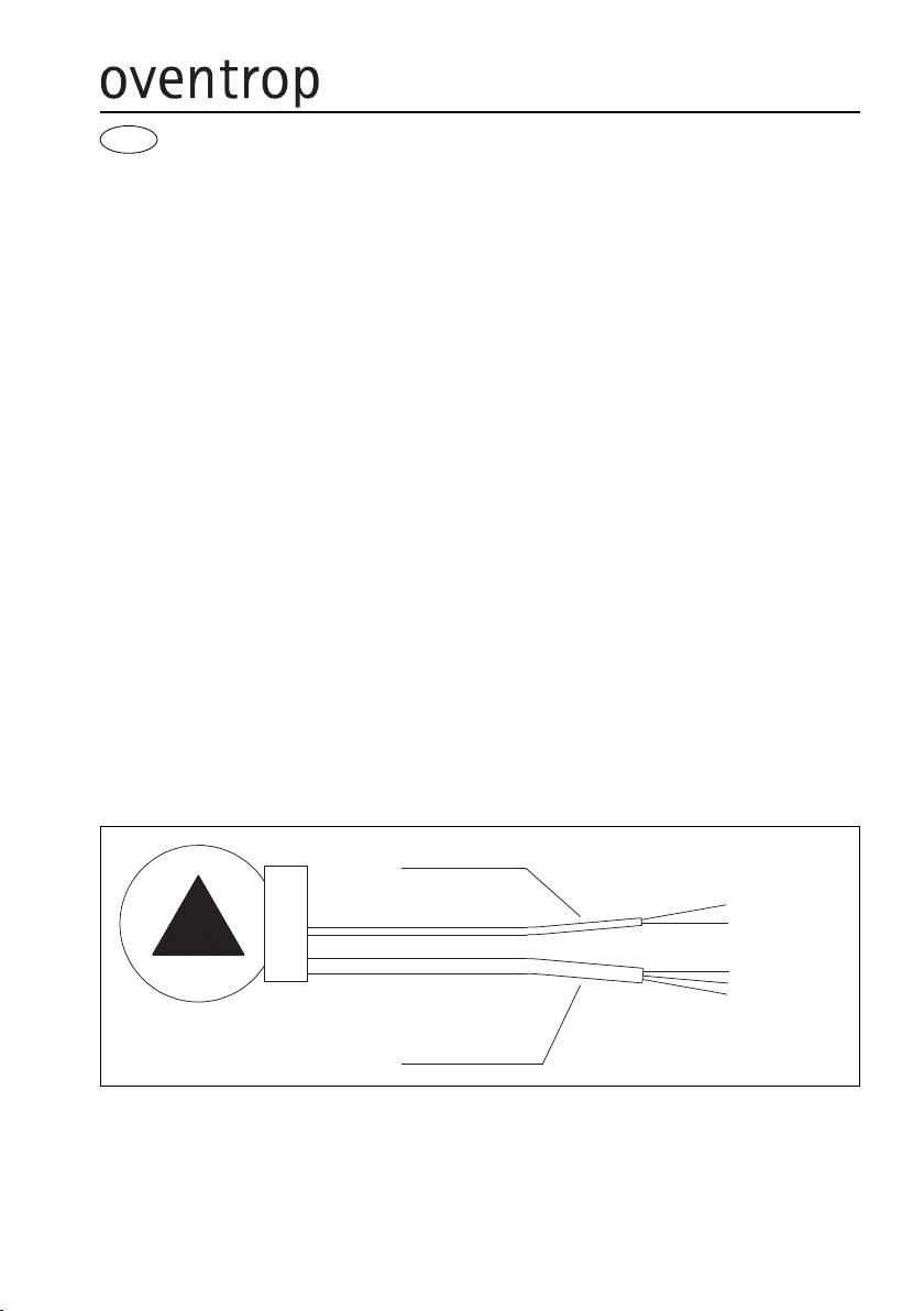
Informations g n rales sur la disposition des raccordements:
Ligne pilote
Alimentation électrique
bleu
L
N
PE
brun
GND (masse)
Sortie signal (modulation
d’impulsions ou 0-10 V)
FR

Technische Änderungen vorbehalten.
Subject to technical modification without notice.
Sous réserve de modifications techniques.
136055081 09/2017
OVENTROP GmbH & Co. G
Paul-Oventrop-Straße 1
D-59939 Olsberg
Telefon +49 (0)2962 82-0
Telefax +49 (0)2962 82-400
E-Mail mail@oventrop.de
Internet www.oventrop.com
Eine Übersicht der weltweiten Ansprechpartner
finden Sie unter www.oventrop.de.
For an overview of our global presence visit
www.oventrop.com.
Vous trouverez une vue d’ensemble des
interlocuteurs dans le monde entier sur
www.oventrop.com.
Table of contents
Languages:
Popular Heat Pump manuals by other brands

Rotex
Rotex RRHQ006ADV3 installation manual

Gree
Gree Crossover GWH09AGC-D3DNA2B/I Operation manual

Robur
Robur GAHP-GS Installation, use and maintenance manual

Bosch
Bosch EP015 Installation and maintenance manual

CTC Union
CTC Union GSi-12 BE Installation and maintenance manual

Waterstage
Waterstage WS G140DC6 Series Installation and operating manual

Danfoss
Danfoss Optyma Blue OP-LGHE068NTA07D instructions

Airxcel
Airxcel Coleman-Mach 47000 SERIES Installation, operation and maintenance instructions

Dimplex
Dimplex LI 11TES Installation and operating instructions

Mitsubishi
Mitsubishi Ecodan installation manual

atecpool
atecpool AMHP110 Installation instructions manual

Carrier
Carrier GW Series installation instructions