www.ovum.at
NHWP06S+
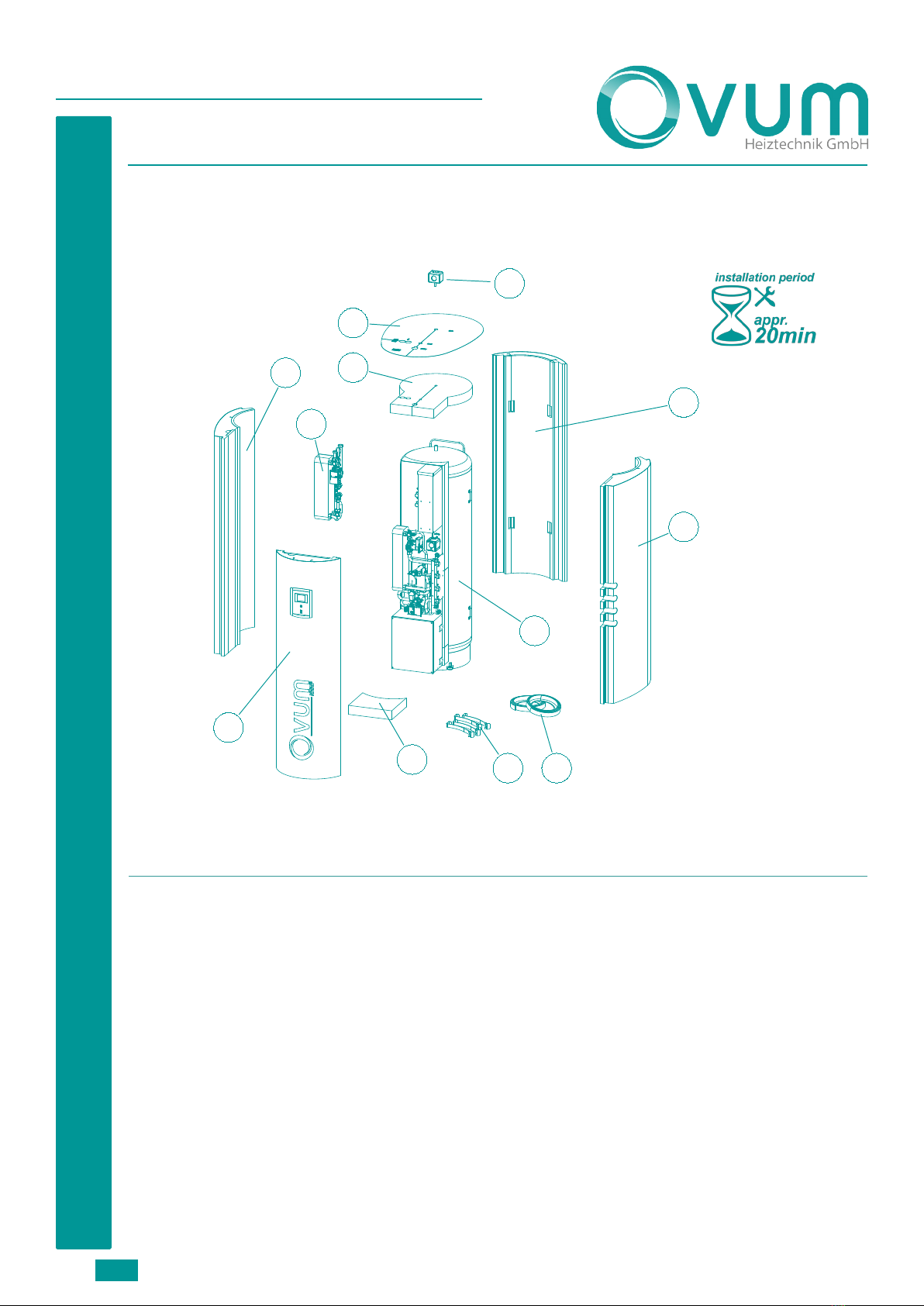
Planning and assembly instructions
Page 3
FUNCTIONS OF THE NHWP
FULLY MODULATING HEAT PUMP
The heat source of the NHWP is a modulating
brine heat pump, which was praised by the
independent AIT test institute for two special
features. The NHWP stood out with its very
high efficiency and therefore, very low
energy consumption on the one hand, and an
extremely large modulation bandwidth of only
1.5 kW to more than 10 kW on the other.
HOT GAS TECHNOLOGY
Every modern household needs two different
temperature levels for its energy supply. A low
level for heating (e.g. underfloor heating 35°C)
and a higher one for hot water (e.g. 55°C).
Conventional heat pumps efficiently prepare
the low level, switching to the higher level
when needed, where they operate at lower
efficiency.
The NHWP solves this task in parallel and more
efficiently with a technology that has been
known for many years with what is know as
hot gas technology. While the heat pump is
in the efficient low-temperature mode (e.g. for
underfloor heating), it also prepares the hot
water by using heat recovery from the hot gas
(heat at the compressor outlet), without any
additional energy input. A smart and efficient
solution, which not only saves energy, but
also allows for higher hot water temperatures
while protecting the heat pump.
FRESH HOT WATER PREPARATION
The hot water preparation integrated in the
NHWP is designed as a FWS (fresh water
system). In this type of hot water preparation,
heating water is stored instead of hot water.
If hot water is drawn, this is heated during
circulation. As a result, each drop of hot water
is fresh water, the same as your usual cold
water. This is a decisive benefit in terms of
hygiene. Even after long time away from home
(e.g. a holiday), fresh water comes out of the
storage tank and not old water.
CONSTANT HOT WATER TECHNOLOGY
With the NHWP, you can set the temperature
for draining off water independently of
the storage temperature. This is a decisive
advantage for you, which is only offered by
the NHWP. If the storage tank is heated to a
higher temperature, e.g. by free solar power
to save energy, you still draw the water at the
usual temperature set by you.
CONTINUOUSLY VARIABLE ENERGY SAVING
PUMPS
The NHWP already has all of the necessary
recirculation pumps built-in. The pump for
the brine circuit and the pump for the heating
circuit are designed as output-controlled
energy saving pumps. With these, they will
automatically adapt perfectly to your local
conditions.
500-LITRE STORAGE
Every integrated heating system requires
a storage tank of a good size. This is already
integrated in the NHWP, which saves any
additional installation. On the one hand, it
makes sure that you always have enough hot
water, and on the other, it is an important
module for storing energy.
THERMAL INSULATION
For maximum efficiency, it is not enough that
energy is prepared economically, it is also
important that downtime losses are minimised.
The thermal insulation not only protects the
heat storage tank, but also uses an innovative
method of protecting all of the necessary
components from heat loss. Whether it is a
recirculation pump, shut-off devices or the
storage tank and heat pump - everything is
under the protective thermal insulation cover.
In this way, the losses are reduced by up to
50%.
THERMAL LOCK
If no more energy is needed in the heating
system, then not only is the heating circuit
pump disabled, but the heating circuit is also
mechanically shut off. This feature ensures
that no unnecessary energy can escape from
the thermal insulation cover via the heater
lines.
E-BACKUP
An integrated electrical heating element is
helpful during initial installation (heating,