8
3. INSTALLATION
Attaching the mounting plate
Once you have determined the final installation position of the system and you have checked again that it is
correctly positioned in relation to the direction of travel (system retracting towards the rear of the vehicle, cable
outlet pointing towards the rear of the vehicle), mark the corner points of the mounting plate.
Next, undo the four retaining nuts and lift the system off the mounting plate. The mounting plate is bonded to
the roof of the vehicle using commercially available highly adhesive body sealing compound and is then secured
by screws, if required. Please use a special cleaning agent to clean the mounting plate and roof as recommended
by the manufacturer of the body sealing compound (e.g. Sikaflex, Teroson 1K-Pur, Würth 'Klebt und Dichtet').
Once the cleaner has dried off, apply the sealing compound to the underside of the mounting plate. Fit the
mounting plate to the roof. If required, secure additionally with the self-tapping screws provided (see drawing).
Take note of the manufacturer’s instructions regarding processing and curing of the adhesive sealing compound
before moving the vehicle! If these times cannot be observed for any reason, the mounting must be additionally
secured by screws.
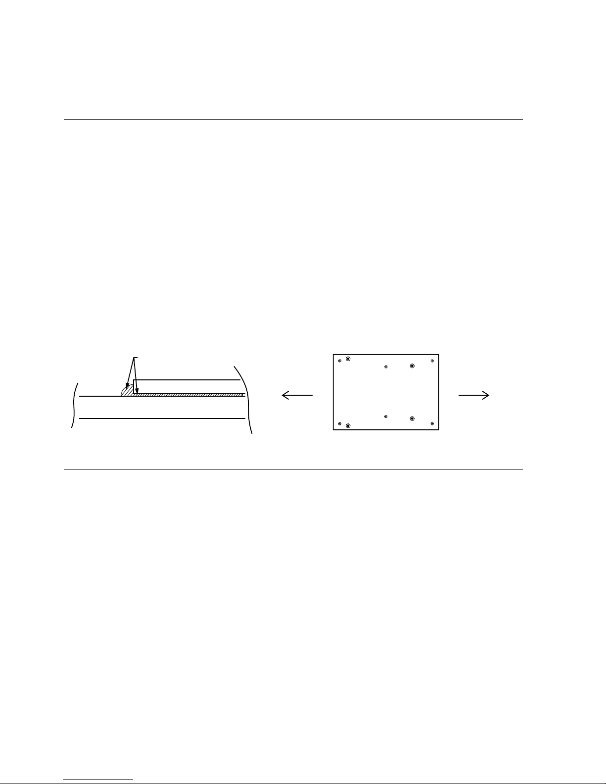
Vehicle roof
Mounting plate
Bonding seal
Rear of vehicle Driving direction
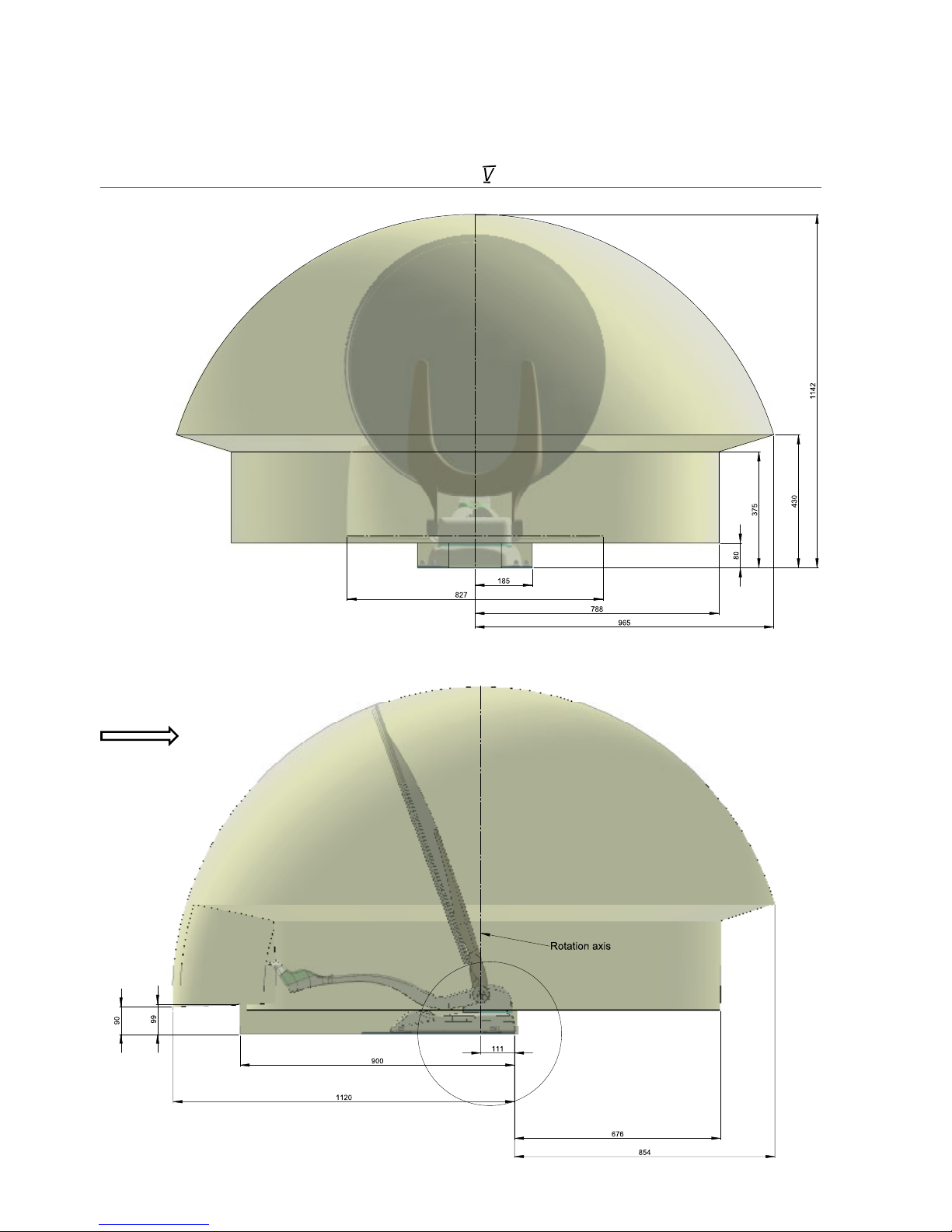
3.2 Mounting the external unit
Place the external unit on the mounting plate with the connector housing and the cable outlet of the external
unit pointing towards the rear of the vehicle. Install the 4 nuts and attach the small covers. An installation in any
other position is not permitted and will cause the warranty to be invalidated. If the mounting plate is positioned
correctly, the wiring outlet must point towards the rear of the vehicle.
ATTACHING THE THREADED ELBOW FITTING (CABLE FEED-THROUGH)
The threaded elbow fitting on the roof must be located with the cable inlet pointing to the rear of the
vehicle, thus protecting it against splash water.
To make the routing of the cables inside the vehicle easier, the distance between the elbow fitting and the con-
trol panel and the receiver should be as short as possible.