A
V~
300 300
20
200 200
2
200m
Ω
OFF
200
200µ
20µ
2k
20k
200k 200m
20m
2m
2M
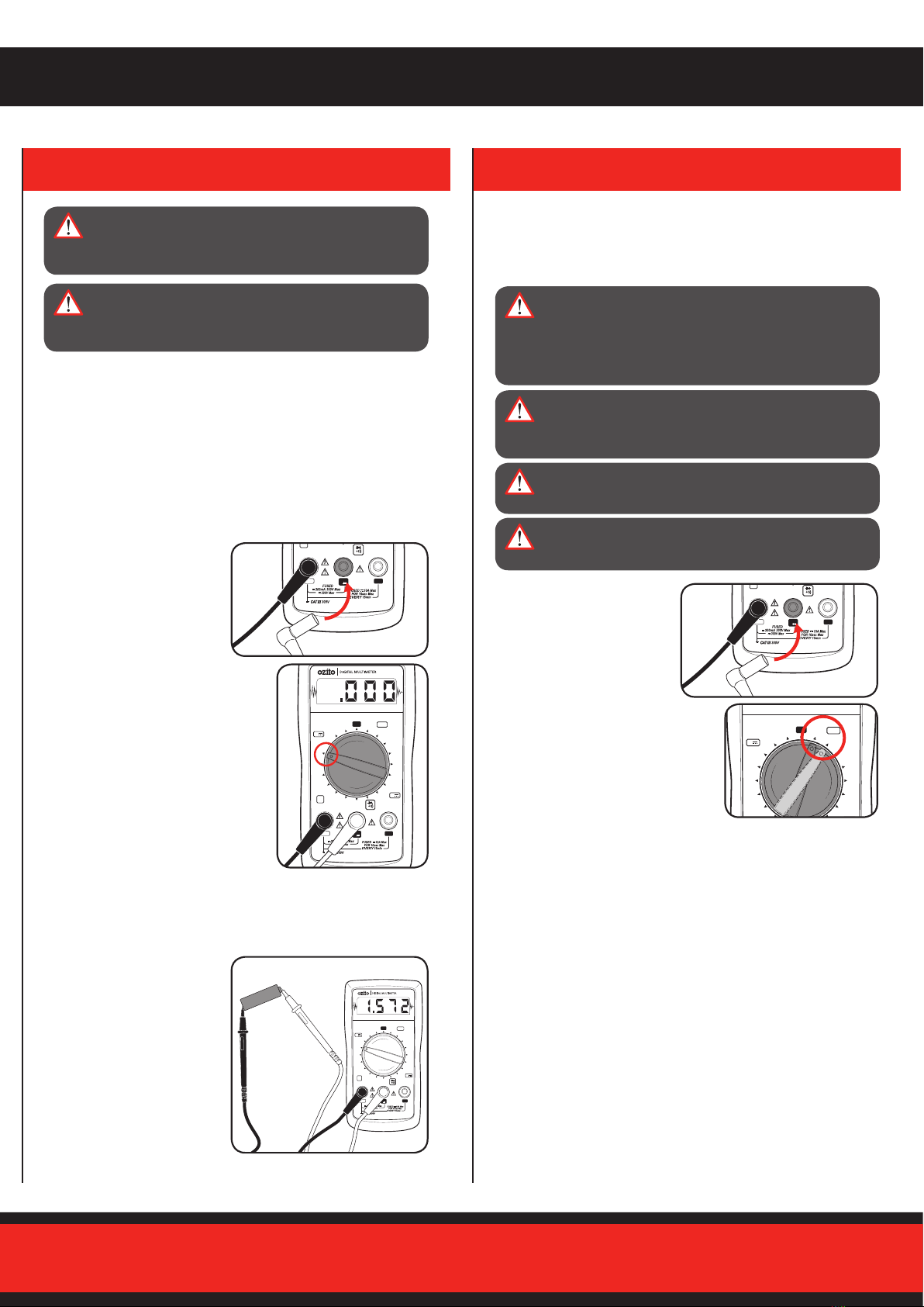
10A
VmA
Ω
V
10A
COM
A
V~
300 300
20
200 200
2
200m
Ω
OFF
200
200µ
20µ
2k
20k
200k 200m
20m
2m
2M
10A
VmA
Ω
V
10A
COM
DIGITAL
MULTIMETER
300V 10A
INSTRUCTION MANUAL
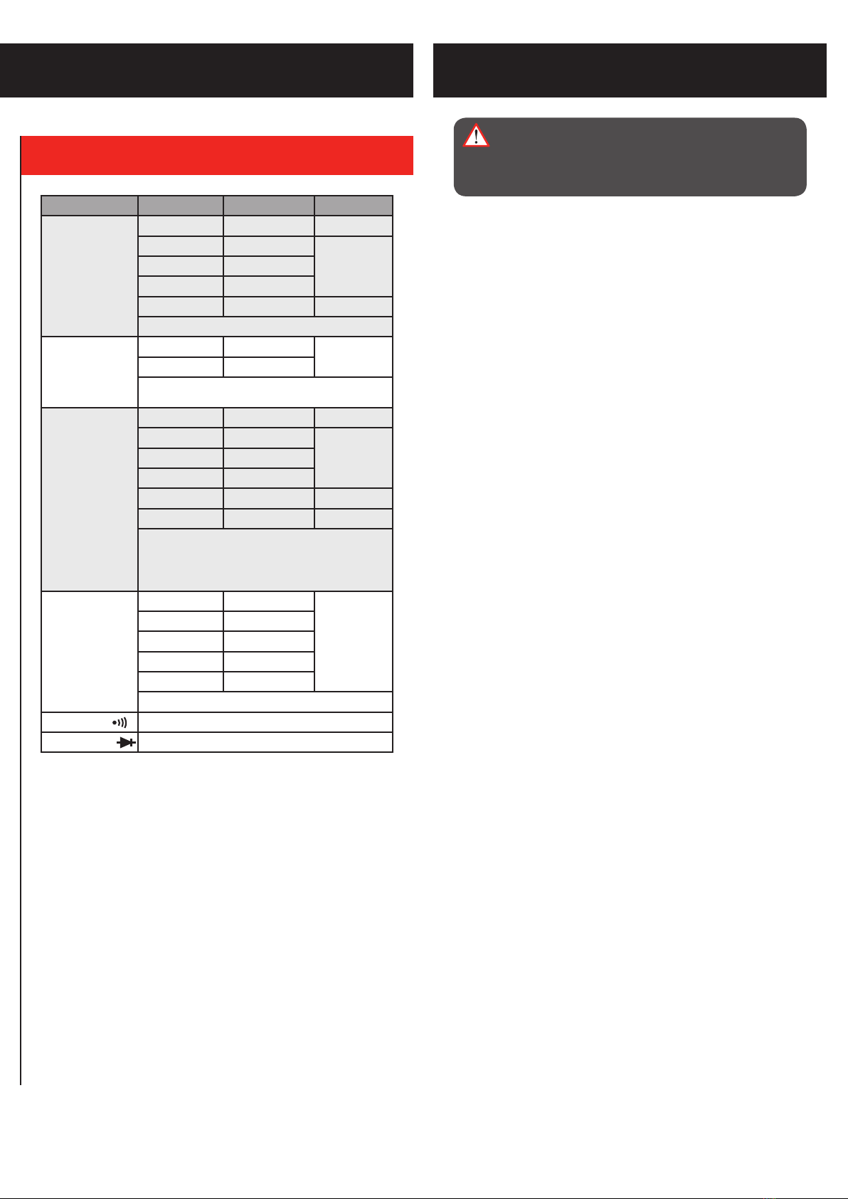
SPECIFICATIONS
Power: 9V DC Battery
Voltage: 200 - 300V (AC)
0.2 - 300V (DC)
Current: 20µ - 10A (DC)
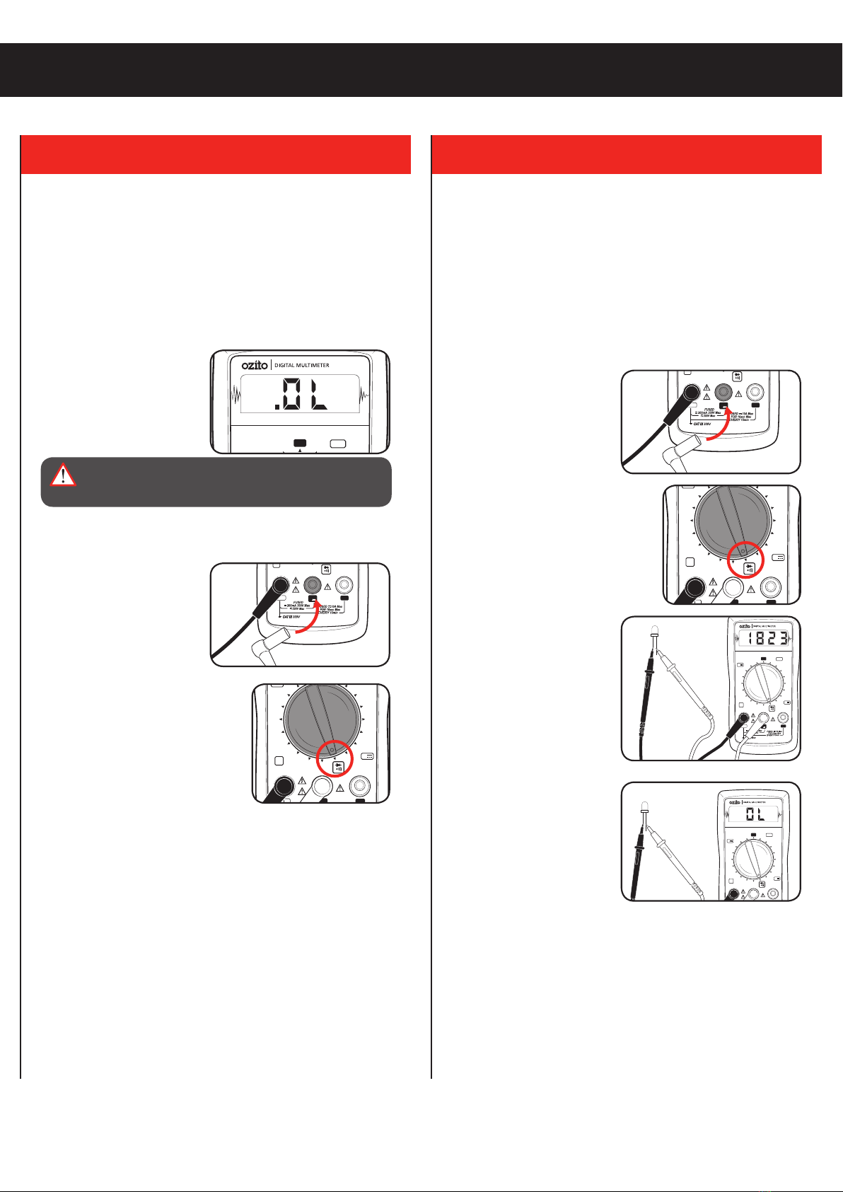
Resistance: 200 - 2MΩ
Diode Check: 2.2V (Open Circuit Voltage)
Continuity Check: <20Ω
Operating Temperature: 0 to 40°C, <75%RH
Weight: 0.23kg
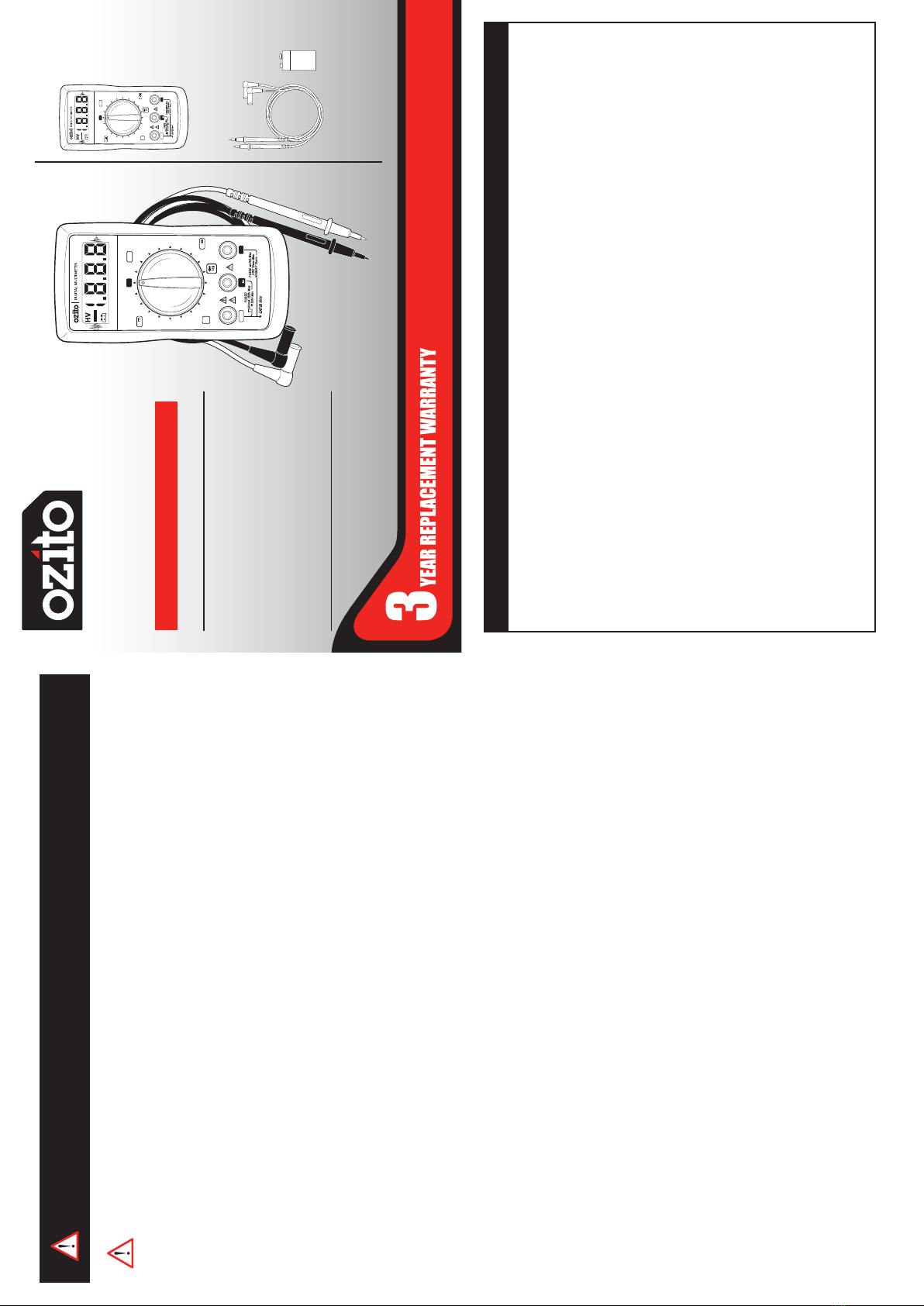
ODMM-300
STANDARD EQUIPMENT
IN ORDER TO MAKE A CLAIM UNDER THIS
WARRANTY YOU MUST RETURN THE PRODUCT
TO YOUR NEAREST BUNNINGS WAREHOUSE WITH
YOUR BUNNINGS REGISTER RECEIPT. PRIOR TO
RETURNING YOUR PRODUCT FOR WARRANTY
PLEASE TELEPHONE OUR CUSTOMER SERVICE
HELPLINE:
Australia 1800 069 486
New Zealand 0508 069 486
3 YEAR REPLACEMENT WARRANTY
Your product is guaranteed for a period of 36 months from the
original date of purchase. If a product is defective it will be replaced
in accordance with the terms of this warranty. Warranty excludes
consumable parts, for example: valve adapters and accessories.
WARNING! The following actions will result in the warranty
being void.
• If the tool has been operated on a supply voltage other than that
specified on the tool.
• If the tool shows signs of damage or defects caused by or
resulting from abuse, accidents or alterations.
• Failure to perform maintenance as set out within the instruction
manual.
• If the tool is disassembled or tampered with in any way.
• Professional, industrial or high frequency use.
WARRANTY
TO ENSURE A SPEEDY RESPONSE PLEASE
HAVE THE MODEL NUMBER AND DATE OF
PURCHASE AVAILABLE. A CUSTOMER SERVICE
REPRESENTATIVE WILL TAKE YOUR CALL AND
ANSWER ANY QUESTIONS YOU MAY HAVE
RELATING TO THE WARRANTY POLICY OR
PROCEDURE.
OZITO Australia/New Zealand (Head Office) 1-23 Letcon Drive, Bangholme, Victoria, Australia 3175.
ozito.com.au
Digital Multimeter
Test Lead Set & 9V Battery
1019
GENERAL POWER TOOL SAFETY WARNINGS
WARNING! Read all safety warnings and all
instructions. Failure to follow the warnings and instructions
may result in electric shock, re and/or serious injury.
Save all warnings and instructions for future reference. The
term “power tool” in the warnings refers to your mains-operated (corded)
power tool or battery-operated (cordless) power tool.
1. Work area safety
a. Keep work area clean and well lit. Cluttered or dark areas invite
accidents.
b. Do not operate power tools in explosive atmospheres, such as
in the presence of ammable liquids, gases or dust. Power tools
create sparks which may ignite the dust or fumes.
c. Keep children and bystanders away while operating a power tool.
Distractions can cause you to lose control.
2. Electrical safety
a. Power tool plugs must match the outlet. Never modify the plug in
any way. Do not use any adapter plugs with earthed (grounded)
power tools. Unmodied plugs and matching outlets will reduce risk of
electric shock.
b. Avoid body contact with earthed or grounded surfaces, such as
pipes, radiators, ranges and refrigerators. There is an increased risk
of electric shock if your body is earthed or grounded.
c. Do not expose power tools to rain or wet conditions. Water entering
a power tool will increase the risk of electric shock.
d. Do not abuse the cord. Never use the cord for carrying, pulling or
unplugging the power tool. Keep cord away from heat, oil, sharp
edges or moving parts. Damaged or entangled cords increase the risk
of electric shock.
e. When operating a power tool outdoors, use an extension cord
suitable for outdoor use. Use of a cord suitable for outdoor use
reduces the risk of electric shock.
3. Personal safety
a. Stay alert, watch what you are doing and use common sense when
operating a power tool. Do not use a power tool while you are tired
or under the inuence of drugs, alcohol or medication. A moment
of inattention while operating power tools may result in serious personal
injury.
b. Use personal protective equipment. Always wear eye protection.
Protective equipment such as dust mask, non-skid safety shoes, hard
hat, or hearing protection used for appropriate conditions will reduce
personal injuries.
c. Prevent unintentional starting. Ensure the switch is in the o-
position before connecting to power source and/or battery pack,
picking up or carrying the tool. Carrying power tools with your nger
on the switch or energising power tools that have the switch on invites
accidents.
d. Remove any adjusting key or wrench before turning the power tool
on. A wrench or a key left attached to a rotating part of the power tool
may result in personal injury.
e. Do not overreach. Keep proper footing and balance at all times.
This enables better control of the power tool in unexpected situations.
f. Dress properly. Do not wear loose clothing or jewellery. Keep your
hair, clothing and gloves away from moving parts. Loose clothes,
jewellery or long hair can be caught in moving parts.
g. If devices are provided for the connection of dust extraction and
collection facilities, ensure these are connected and properly used.
Use of dust collection can reduce dust-related hazards.
h. Do not let familiarity gained from frequent use of tools allow you
to become complacent and ignore tool safety principles. A careless
action can cause severe injury within a fraction of a second.
4. Power tool use and care
a. Do not force the power tool. Use the correct power tool for your
application. The correct power tool will do the job better and safer at
the rate for which it was designed.
b. Do not use the power tool if the switch does not turn it on and o.
Any power tool that cannot be controlled with the switch is dangerous
and must be repaired.
c. Disconnect the plug from the power source and/or the battery pack
from the power tool before making any adjustments, changing
accessories, or storing power tools. Such preventive safety
measures reduce the risk of starting the power tool accidentally.
d. Store idle power tools out of the reach of children and do not allow
persons unfamiliar with the power tool or these instructions to
operate the power tool. Power tools are dangerous in the hands of
untrained users.
e. Maintain power tools. Check for misalignment or binding of moving
parts, breakage of parts and any other condition that may aect the
power tool’s operation. If damaged, have the power tool repaired before
use. Many accidents are caused by poorly maintained power tools.
f. Keep cutting tools sharp and clean. Properly maintained cutting tools
with sharp cutting edges are less likely to bind and are easier to control.
g. Use the power tool, accessories and tool bits etc. in accordance
with these instructions, taking into account the working conditions
and the work to be performed. Use of the power tool for operations
dierent from those intended could result in a hazardous situation.
h. Keep handles and grasping surfaces dry, clean and free from oil
and grease. Slippery handles and grasping surfaces do not allow for
safe handling and control of the tool in unexpected situations.
5. Service
a. Have your power tool serviced by a qualied repair person using
only identical replacement parts. This will ensure that the safety of
the power tool is maintained.
The benefits provided under this warranty are in addition to other
rights and remedies which are available to you at law.
Our goods come with guarantees that cannot be excluded at law. You
are entitled to a replacement or refund for a major failure and for
compensation for any other reasonably foreseeable loss or damage.
You are also entitled to have the goods repaired or replaced if the
goods fail to be of acceptable quality and the failure does not amount
to a major failure.
Generally you will be responsible for all costs associated with a claim
under this warranty, however, where you have suffered any additional
direct loss as a result of a defective product you may be able to claim
such expenses by contacting our customer service helpline above.