VICI VC837 User manual

VC837 DIGTAL MULTIMETER Operation Manual
1. General Description
This is a 3 1/2 digital multimeter with high stablility and performance. It uses a LCD with
20mm high figure, which makes the reading clearer and the operation more convenient.
It can test DCV, ACV, DCA, ACA, resistance, capacitance, frequency, NC
V
,dutycycle,
temperature, diode, and continuity. This meter also designed with functions including
unit symbol display, data hold, lighting, auto range, auto power off and warning
functions. To assure high accuracy and resolution, it adopts integrated circuit 8‐bit
microprocessor and a dual integral A/D conversion as LCD driver, giving high resolution
and high accurac
y
. It is an ideal tool for labs, factories and radio‐technology.
2. Safety Instructions
The instrument is designed in compliance with IEC1010 standard (safety standard issued
by International Electro technical Committee). Please read the followingsafety
instructions before operation.
2.1 Check the connection and insulation of test leads to avoid electric shock.
2.2 To avoid electric shock and damage to the meter, do not input voltage exceeding
rated value.
2.3 When measuring voltage higher than DC 60V or AC 40V, please be careful andavoid
electric shock.
2.4 Select correct function and range to avoid wrong operation.
2.5 Move the test leads away from test points when switching to other function.
2.6 Don’t input voltage in current terminal.
2.7 Don’t make any modification to the circuit. It may damage the meter or jeopardize
safety.
2.8 Safety symbols:
“”Highvoltage,“ ”GND,“ ” Dual insulation, “ ” Refer to manual, “ ”Low
battery indication.
3. Features
3.1 General Characteristics
3.1.1 Display: LCD;
3.1.2 Max display: 6000 (3 5/6 digits, automatic polarity, and unit symbol display);
3.1.3 Measurement method: Analog to digital converter (in micro processorADC+MCU);
3.1.4 Sampling rate: approx.3 times/sec.
3.1.5 Over‐range display: “OL” displayed.
3.1.6 Low battery indicator: “ ”
3.1.7 Working environment: (0~40)℃, relative humidity: <80%;
3.1.8 Store condition: (‐10~50)℃, relative humidity: <80%
3.1.9 Battery: 2 pieces 1.5V battery (“AAA” 7# battery);
3.1.10 Dimension: 140×72×37mm (length x width x height);
3.1.11 Weight: approx. 195g (including battery);
3.1.12 Accessories: test leads, TP01 thermocouple, user manual, holster,giftbox,and
2*1.5V batteries.
3.2 Technical Features
3.2.1 Accuracy: ± (a% × reading + digits). To assure accuracy, the ambient temperature
should be (23±5) ℃, relative humidity <75%. One year accuracy is guaranteed since
production date.
3.2.2 DC Voltage(DCV)
Range Accuracy Resolution
600mV
±(0.5%+4)
0.1mV
6V 1mV
60V 10mV
600V ±(1.0%+4) 100mV
Input impedance: at 200mv range >40MΩ, at other ranges is 10MΩ.
Overload protection: 600V DC/AC rms.
3.2.3. AC Voltage(ACV)
Range Accuracy Resolution

6V
±(0.8%+6)
1mV
60V 10mV
600V ±(1.0%+6) 100mV
Input impedance: 10MΩ.
Overload protection: 600V DC/ AC rms.
Frequency response: at 600V range: (40~1000)Hz, at other ranges: (40~2000)Hz
Displaying: True RMS response (calibration based on sine wave RMS)
3.2.4 DC Current(DCA)
Range Accuracy Resolution
600uA
±(1.0%+5)
0.1μA
6000uA 1μA
60mA 10μA
600mA 100μA
6A 1mA
10A ±(2.0%+5) 10mA
Maximum voltage drop: 200 mV for full range.
Maximum input current: 10A (within 10 seconds).
Overload protection: 0.5A/250V fuse and 10A/250V fuse.
3.2.5 AC Current (ACA)
Range Accuracy Resolution
600uA
±(1.5%+5)
0.1μA
6000uA 1μA
60mA 10μA
600mA 100μA
6A 1mA
10A ±(2.0%+10) 10mA
Maximum voltage drop: 200 mV for full range.
Maximum input current: 10A (within 10 seconds).
Overload protection: 0.5A/250V fuse and 10A/250V fuse.
Frequency response: 10A range: 40~100Hz, other ranges: 40~400Hz.
3.2.6 Resistance(Ω)
Range Accuracy Resolution
600Ω ±(0.8%+5) 0.1Ω
6kΩ
±(0.8%+1)
1Ω
60kΩ 10Ω
600kΩ 100Ω
6MΩ 1kΩ
60MΩ ±(1.2%+5) 10kΩ
Open circuit voltage: 500mV
Overload protection: 250V DC/AC peak value.
3.2.7 Capacitance (C)
Range Accuracy Resolution
60nF ±(2.5%+6) 10pF
600nF ±(2.5%+5) 100pF

6uF 1nF
60uF 10nF
600uF
±(5.0%+8)
100nF
6mF 1uF
60mF 10uF
Overload protection: 250V DC/AC peak value.
3.2.8 Frequency
Range Accuracy Resolution
10Hz
±(0.5%+4)
0.01Hz
100Hz 0.1Hz
1000Hz 1Hz
10kHz 10Hz
100kHz 100Hz
1MHz 1kHz
10MHz 10kHz
Input sensitivity: 0.7V rms.
Overload protection: 250V DC/AC peak value.
3.2.9 Diode and Continuity Test
Measurement Range Test conditions
Diode forward voltage drop.
Forward DC current is
approx 0.8mA,
reverse voltage is
approx 2.2V.
When the resistance under test
is less than 50Ω, buzzer sounds
continuously.
Open circuit voltage:
2.2V
Overload protection: 250V DC/AC peak value.
WARNING: Do not input voltage at this range!
3.2.10 Temperature (℃/℉)
Range Accuracy Resolution
‐40℃~1000℃<400℃±(1.0%+5)
≥400℃±(1.5%+15) 1℃
0F~1832℉<750℉±(1.0%+5)
≥750℉±(1.5%+15) ℉
Thermocouple: K type.
WARNING: do not input voltage at this range!
Operation
4.1 Panel Description
①. LCD: Display the data and unit symbol
Number Feature Description
1△
Relative (REL) mode is active
2Data Hold is active.
3-Indicates negative readings.
4DC
DC voltage or current measurement.
5AC
AC voltage or current measurement.
6AUTO
Auto range mode.
7Null
8Diode test mode.
9The continuity beeper is on.
10 MAX MIN Null
11 APO Auto power off symbol.
12 The symbol of high voltage risk indication.
13 Low battery indication. Warning: To avoid error readings, which could leadto
possible electric shock or personal injury, please replace the battery in time.
14
hFE
%,℃,℉
MΩ,kΩ,Ω
Hz,kHz,MHz
mV, V
uA, mA, A
Null;
Null;
Duty cycle, Degrees Celsius, Degrees Fahrenheit;
Megohm, Kilohm, Ohm;
Hertz, Kilohertz, Megahertz;
Millivolts, Volts;
Microamp, Milliamp, Amperes (A).
②
. Rotary switch: it is used to change the range and choose functions.

Switch
position Description
AC voltage measurement. Press SELECT key to switch between frequency/ dutycycle
measurements.
DC voltage measurement.
ΩResistance measurement.
Diode/continuity measurement. Press SELECT key to choose diode or continuity range.
Capacitance measurement.
Hz Frequency measurement, Press SELECT key to switch between frequency/ duty cycle
measurements.
℃/℉ Temperature measurement, press SELECT key to choose ℃or ℉.
NCV Non‐contact voltage detector.
DC current measurement (from 0uA to 6000uA). Press SELECT key to switch to AC
current measurement (from 0uA to 6000uA).
DC current measurement (from 0mA to 600mA). Press SELECT key to switch to AC
current measurement (from 0mA to 600mA).
DC current measurement (from 0A to 10A). Press SELECT key to switch to AC current
measurement (from 0A to 10A).
③Input Terminal
Terminal Description
A Input terminal for AC and DC current from 0 to 10.00A (Overload for max 10 seconds).
VΩmA
Input terminal for voltage, resistance, diode, and continuity, and temperature positive
(+) terminal. AC and DC current from 0uA to 600mA (Max 18 hours for less than
600mA).
COM Common terminal for all measurements, and temperature negative (‐) terminal.
④Function Key
SELECT/ Key:
1) Select function: Press SELECT key to choose DC or AC measurement under
ranges. Under (Diode/Continuity) range, press SELECT key can choose
(diode test) or (continuity test). Under temperature ranges, press SELECT key to
choose Degrees Celsius or Degrees Fahrenheit. Under ACV ranges, press SELECT key
to switch between Frequency or Duty Cycle measurement.
2) When there is no measurement in 15 minutes, the meter will automatically power
off and enter sleep mode. One minute before sleep mode, the buzzer will beep for 5
times to remind user. Press any button or turn the rotary switch will exit the sleep
mode.
3) Press SELECT key to active the meter from the sleep mode or hold the SELECT key
down when turn on the meter to cancel auto power off function.
4) TORCH FUNCTION Key: Press TORCH FUNCTION key for more than 2 seconds to turn
on the torch. Ppress it for more than 2 seconds once again to turn off the torch.
RANGE/REL Key
1) Auto range is the default when you turn on the meter, and the meter displays
“AUTO” symbol. Press RANGE to enter manual range mode. Press RANGE to switch
between the ranges available for the selected function. Hold the RANGE button
down for more than 2 seconds to return to auto ranging,
2) Under capacitance measurement, press REL key to enter relative value test mode.
The display is zeroed, and △symbol appears. Press REL key again to exit relative
value test mode.
HOLD/ Light Key
1) HOLD Key : Press HOLD key to enter HOLD mode. The current value will be hold,and
symbol “ “ will be displayed. Press HOLD again to exit the HOLD mode.
2) Light Key: Press HOLD key for more than 2 seconds to turn on the backlight. The
backlight can last for 15 seconds. During 15 seconds, press “ ” light key for 2
seconds again to turn off the backlight.
⑤Non‐contact voltage detector area.
⑥Holster, Battery door.
See picture.
4.2 DCV measurement
4.2.1 Insert the black test lead into “COM” terminal, and the red one into “VΩmA”
terminal.
4.2.2 Turn the rotary to switch to “ ” ranges. Under Auto Range status, it will display
“AUTO” symbol. Press “RANGE/REL” key can change to Manual range, the available
AUTO POWER OFF
T
R
U
E
R
M
S
M
U
L
T
I
M
E
T
E
R

ranges are 600mV, 6V, 60V, 600V.
4.2.3 Connect test leads to the test point; LCD will display polarity and voltage of the test
point connected by the red test lead.
NOTE:
1) If LCD display “OL” under manual range, it means it is over range, now you need to
select a higher range.
1) Do not input voltage over 600V. Or it may cause damage to the circuit of the meter,
and the built‐in buzzer will alarm.
2) Be careful while measuring a high voltage circuit. DO NOT touch the high voltage
circuit.
4.3 ACV measurement
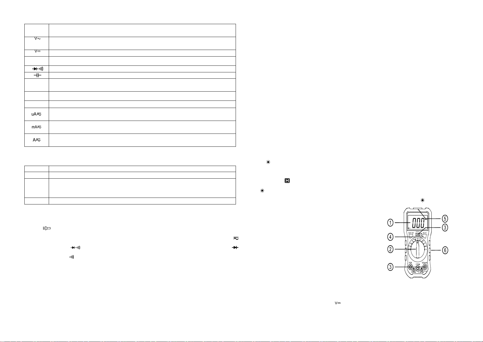
4.3.1 Insert the black test lead into “COM” terminal, and the red one into “VΩmA”
terminal.
4.3.2 Turn the rotary to switch to “ ” ranges. Under Auto Range status, it will display
“AUTO” symbol. Press “RANGE/REL” key can change to Manual range, the available
ranges are 600mV, 6V, 60V, 600V; Press “SELECT” key to switch between
Frequency/Duty cycle measurement.
4.3.3 Connect test leads to the test point; LCD will display voltage of the test point
connected by the test leads.
NOTE:
2) If LCD display “OL” under manual range, it means it is over range, now you need to
select a higher range.
1) Do not input a voltage over 600V. Or it may cause damage to the circuit of the
meter, and the built‐in buzzer will alarm.
2) Be careful while measuring a high voltage circuit. DO NOT touch the high voltage
circuit.
4.4 DCA measurement
4.4.1 Insert the black test lead into “COM” terminal and the red one into “VΩmA”
terminal (Max.600mA) or into “10A” terminal (Max.10A);
4.4.2 Turn the rotary switch to Current ranges, auto range is the default when you turn
on the meter, “AUTO” symbol displayed. Press “RANGE/REL” key can change to Manual
range, the available ranges are 600uA, 6000uA, 60mA, 600mA, 6A, 10A.
4.4.3 Connect test leads to the tested circuit; LCD will display polarity and current of the
test point connected by the red test lead.
NOTE:
1) If you are not sure about the range of current under test, please select thehighest
range, and then select the proper range based on displaying value.
2) If the LCD displays “OL”, it means the current is over range. Now you need toselect
ahigherrange.
3) Maximum input current is 600mA or 10A (subject to which terminal the red test lead
is inserted into). Current exceeding rated value will damage the fuse, and may cause
damage to the circuit of meter.
4.5 ACA measurement
4.5.1 Insert the black test lead into “COM” terminal and the red one into “VΩmA”
terminal (Max.200mA) or into “10A” terminal (Max.10A);
4.5.2 Turn the rotary switch to a proper cuttent range. Press “SELECT/ ”keytoselect
the AC mode, auto range is the default when you turn on the meter, “AUTO” symbol
displayed. Press “RANGE/REL” key can change to Manual range, the availablerangesare
600uA, 6000uA, 60mA, 600mA, 6A, 10A.
4.5.3 Connect test leads to the tested circuit; LCD will display the currentofthetest
point.
NOTE:
1) If you are not sure about the range of current under test, please select thehighest
range, and then select the proper range based on displaying value.
2) If the LCD displays “OL”, it means the current is over range. Now you need toselect
ahigherrange.
3) Maximum input current is 600mA or 10A (which terminal the red test lead is
inserted into). Current exceeding rated value will damage the fuse, and maycause

damage to the circuit of meter.
4.6 RESISTANCE measurement
4.6.1 Insert the black test lead into “COM” terminal and the red one into “VΩmA”
terminal;
4.6.2 Turn the rotary switch to “Ω ”ranges,press“SELECT/ ” key to select “Ω”
mode. Connect two test leads across the resistor under test;
4.6.3 Auto range is the default when you turn on the meter, “AUTO” symbol displayed.
Press “RANGE/REL” key can change to Manual range, the available ranges are 600Ω,6k
Ω, 60kΩ, 600kΩ,6MΩ, 60MΩ.
NOTE:
1) If you are not sure about the range of current under test, please select thehighest
range;
2) If LCD displays “OL”, it means it is over range. Now you need to select a higher range.
When measuring value is over 1MΩ, the reading will take a few seconds to be stable.
It’s normal for high resistance measurement;
3) When input terminal is in open circuit, LCD will display “OL”;
4) Before measuring in line resistor, make sure that the power is off and all capacitors
are discharged completely;
5) When there is big error, it may be affected by other online component or there is
voltage on the resistor;
6) Do not input any voltage at resistance range.
4.7 CAPACITANCE MEASUREMENT
4.7.1 Insert the black lest lead in “COM” terminal and the red one in “VΩmA” terminal;
4.7.2 Turn the rotary to switch to “ ”range;
4.7.3 If the LCD doesn’t display “0”, press “RANGE/REL” to clear the reading;
4.7.4 Connect the capacitor to “COM” and “VΩmA” terminal. (Note: the red test leads is
for positive pole +). LCD displays capacitance value.
NOTE:
1) Don’t input voltage or current under capacitance ranges;
2) Press “RANGE/REL” to clear the reading before testing to assure the accuracy;
3) There is only the auto range mode under the capacitance range;
4) The capacitor must be completely discharged before testing to avoid damage the
meter,;
5) The reading of a higher than 600uF range will take more several seconds to be
stabled.
4.8 FREQUENCY MEASUREMENT
4.8.1 Insert the lest leads or shielded cable into “COM” terminal and “VΩmA” terminal;
4.8.2 Turn the rotary to switch to “Hz” range, connect the test leads or shielded cable to
the signal source or the load which is tested (It should over 3Hz).
4.8.3 Press “SELECT/ ” key to choose frequency/duty cycle measurement, LCD will
display the frequency or duty cycle of the tested signal source.
NOTE:
1) There is only the auto range mode under the frequency range;
2) When the input is higher than 10V AC rms, please switch to range and then
select frequency or duty cycle to measure;
3) In noisy environment, it's better to use shield cable to measure a low signal;
4) Do not touch the high voltage circuit when measuring high voltage circuit;
5) Don’t input voltage higher than 250V DC/AC peak value under Hz ranges, or it may
damage the meter.
4.9 NON‐CONTACT VOLTAGE (NCV) DETECT
WARNING:
This function could be affected by different external interference sources, and then the
alarm is activated by wrong signal. The measurement result is for referenceonly.
Turn the rotary function switch to “NCV” position. When the testing circuitisplaced
above the meter, the meter displays the strength of signal, and the buzzer alarms with
“beep beep”.
NOTE:

1) Even if there is no voltage indication, there may be voltage on the circuit. Do not
rely on NCV detector as the only way to detect voltage.
2) Voltage detecting may be affected by power socket design, type of insulation and its
thickness and other factors.
3) Interference sources in the external environment, such as flashing light, motor,
would cause wrong signal to activate alarm function.
4.10 DIODE AND CONTINUITY TEST
4.10.1 Insert the black test lead into “COM” terminal and the red one into “VΩmA”
terminal (the polarity of red lead is “+”);
4.10.2 Turn the rotary switch to “Ω ” range, and press “SELECT/ ”keytochoose
“”mode;
4.10.3 Forward measurement: connect red test lead to the positive polarityandthe
black test lead to the negative polarity of the diode. LCD will display the approx. value of
forward voltage drop;
4. 10.4 Backward measurement: connect red test lead to the negative polarity and the
black test lead to positive polarity of the diode. LCD will display “OL”;
4.10.5 The complete diode test includes forward and backward measurement,ifthe
result doesn’t meet the descriptions above; it means the diode is broken;
4.10.6 Press “SELECT/ ” key to select the continyity measurement mode;
4.10.7 Connect test leads to two points of tested circuit, if the resistanceislessthan50
Ω, the built‐in buzzer sounds.
NOTE:
1) DO NOT input voltage at “Ω”range.
2) When test circuits, make sure the power is off and all capacitors are discharged. Any
negative potential or AC signal will activate the buzzer.
4.11 TEMPERATURE MEASUREMENT
4.11.1 Turn the rotary switch to “℃/℉” range. Press “SELECT/ ”keytoselect ℃or
℉mode.
4.11.2 Insert the cold end (free end) of thermocouple in “VΩmA(+)” and “COM(‐)”
terminal, and put the working end (temperature measuring end) of thermocouple on the
surface or inside the tested object. Then LCD will display the temperature of tested
object, and the reading is in ℃/℉(when the polarity is contrary. The reading will
decrease when the temperature of the tested object increase).
NOTE:
1) When the input terminal is open circuit, it will display the environment
temperature.
2) To ensure measure accuracy, do not replace the temperature probe unless it is
necessary.
3) Do not input voltage at temperature range.
5. MAINTENANCE
This meter is a precise instrument. Any modification to the circuit is not allowed.
NOTE:
1) Don’t input the voltage value higher than 600V DC or ACrms.
2) Don’t input voltage at current, resistance, diode or continuity range.
3) Don’t make any measurements when the battery is not properly installed orthe
back cover isn’t fixed.
4) Before replacing battery or fuse, please remove the test leads from the measuring
point and turn off the power.
5) Keep the meter away from water, dust and shock.
6) Don't expose the meter under high temperature, high humidity, combustible,
explosive and strong magnetic place.
7) Wipe the case with a damp cloth and detergent. Do not use abrasives and alcohol to
clean the meter.
8) If the meter will not be used for a long time, please take out the battery to avoid
leakage damage.
9) When “ ” symbol is displayed, please replace the battery according to the
following steps:
1Remove the holster at first.
2Screw off the fixing screws of the battery door and remove the cover;

3Take off the old battery and replace with a new one. To extend the using life,
it's better to use alkaline battery.
4Fix the battery door.
5Put on the holster.
10) Fuse replacement: When replacing fuse, please use fuse with same type and
specification.
1Remove the holster first, then screw off the fixing screws of the battery door
and back cover to remove the cover;
2Take off the old fuse and replace with a new one.
3Install the back cover, then fix the screws of the battery door and back cover.
Put on the holster.
6. Trouble Shooting
If the meter does not work properly, please check the meter as following steps:
(If the problems still cannot be solved, please refer to repairing center or contact the
local dealers.)
Fatult Solution
No reading on LCD
Turn on the power;
Release the HOLD key;
Replace battery.
signal appears Replace battery.
No input Replace fuse.
Big error Value Replace battery.
●The specifications are subject to changes without prior notice;
●The content of this manual is regarded as correct. If users find out any mistakes or
omissions, please kindly contact the manufacturer;
●The manufacturer will not be responsible for accidents and damage caused by
improper operations;
●The functions described in this User Manual shall not be considered as the reason
for any special usages;
Table of contents
Popular Multimeter manuals by other brands

Klein Tools
Klein Tools MM720 instruction manual

Elenco Electronics
Elenco Electronics M-1000B Operator's instruction manual

Elenco Electronics
Elenco Electronics M-2665K Assembly and instruction manual

Koso
Koso BA010001 RX-2 user manual

Fluke
Fluke 8508A Extended specifications

Kusam-meco
Kusam-meco KM 629 instruction manual