Pacific Scientific 5630 User manual

5630 Drive
Installation & Hardware Reference Manual
110 Fordham Road
Wilmington, MA 0188
7
(978) 988-980
0
Fax (978) 988-994
0
Part# 903-563040-01
List Price $25 U.S.
April, 200
0
Rev E
HIGH PERFORMANCE MOTORS & DRIVES

This document is copyrighted by Pacific Scientific Company. It is supplied
to the user with the understanding that it will not be reproduced,
duplicated, or disclosed in whole or in part without the express written
permission of Pacific Scientific Company.
Pacific Scientific Company has attempted to insure that the information
contained in this manual was correct and accurate at the time of printing.
Pacific Scientific Company cannot be responsible for any typographical
errors or mistakes contained in this manual. The information in this
manual is subject to change without notice.
Copyright © 1989, 1990, 1995, 1996, 1997, 2000

WARNING
The 5630 contains hazardous voltages that can cause severe shock or burn.
The hazardous voltage symbol, shown above, is displayed in this manual
whenever a warning about hazard voltage is required. Refer to Section 2.3,
“Safety Guidelines,” for a summary of the safety guidelines.
As the user or person applying this unit, you are responsible for
determining suitability of this product for any application you intend. In no
event will Pacific Scientific Company be responsible or liable for indirect or
consequential damage resulting from the use of this product.

Table of Contents
...............................................
1 Overview of the 5630 Stepper Motor Drive 1 - 1
1.1 5630 Definition ···························1-1
1.2 Other System Components ·····················1-3
1.3 How to Use this Manual ······················1-4
2 Installing the 5630 Stepper Motor Drive 2 - 1
2.1 Unpacking and Inspecting the 5630 ·················2-1
2.2 Selecting Other System Components ················2-2
2.3 5630 Safety ·····························2-2
2.4 Mounting the 5630 in Your Installation···············2-4
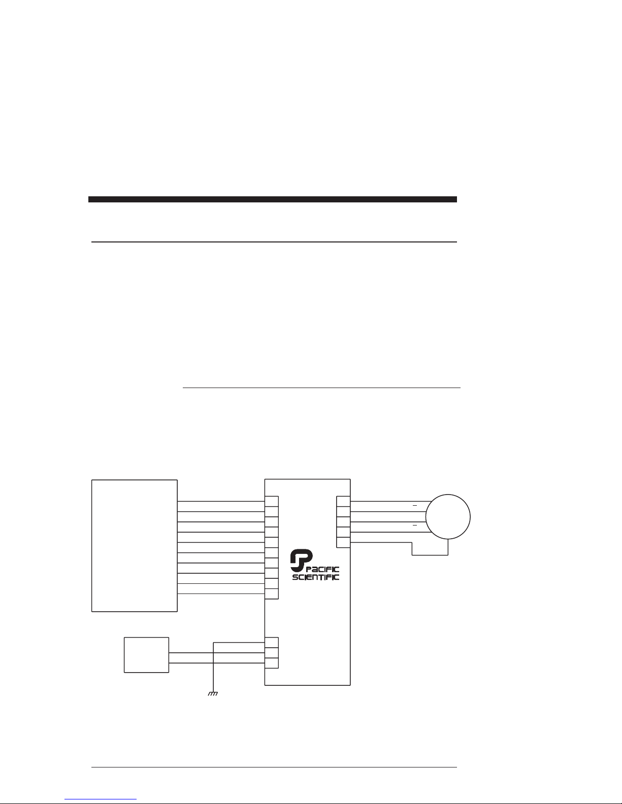
2.5 Connecting the Three Input/Output Cables ·············2-6
2.5.1 J1 Motor Connection ........................2-8
2.5.2 J2 115 V ac Power Connection ..................2-14
2.5.3 J3 Signal Interface Connection ..................2-16
2.6 Setting Up Functions Using Switch SW1··············2-20
2.6.1 Step Set Up ............................2-21
2.6.2 Mid-Range Instability Control Set Up ..............2-22
2.6.3 Idle Current Reduction Set Up..................2-23
2.6.4 Current Set Up ..........................2-24
3 Powering Up the 5630 Stepper Motor Drive 3 - 1
3.1 Testing the Installation ·······················3-1
3.2 Troubleshooting ··························3-4
3.2.1 POWER LED Not On - 5630 Does Not Power Up .......3-5
3.2.2 ENABLED LED Not On - 5630 Does Not Recognize
Enable Input ............................3-7
3.2.3 STEP ACTIVE LED Not on or Motor Does not Step......3-8
3.2.4 POWER FAULT LED On - 5630 Contains Power Fault ....3-9
3.2.5 OVER TEMP LED On - 5630 Senses Excessive Temperature 3-10
Rev E 5630 Installation and Hardware Reference Manual

3.3 Repairing or Replacing the 5630 ·················3-11
Appendix A - Specifications A - 1
Appendix B - Order Number and Ordering Information B - 1
Appendix C - Connections Summary C - 1
Appendix D - Switch Summary D - 1
5630 Installation and Hardware Reference Manual Rev E

1 Overview of the 5630 Stepper
Motor Drive
In this Chapter This Chapter introduces the 5630 Stepping Motor Drive.
Topics covered are:
•5630 definition
•Other system components
•How to use this manual
•Warranty
1.1 5630 Definition
The Pacific Scientific®5630 Stepper Motor Drive is an
electronics package that converts step and direction inputs to
motor winding currents to control a two-phase bipolar
stepping motor.
The output current of the 5630 is switch selectable from 5.0 to
8.0 amps/phase RMS (7.1 to 11.3 amps peak) with a 160-volt
nominal dc bus. The 5630 leaves the factory set at 5.0
amps/phase RMS.
Standard
features Bipolar chopper drive -controls motor current at 20 kHz
chopper frequency.
Internal power supplies - operate from the 115-volt ac input.
The main motor supply consists of a full wave bridge rectifier
into a capacitive input filter with in-rush current limiting.
Shunt regulator circuitry -protects the drive by removing
energy from the supply if the dc bus voltage exceeds 200 volts.
This feature protects the circuitry from excessive voltage that
may be generated under certain motor deceleration
conditions.
Rev E 5630 Installation and Hardware Reference Manual 1 - 1

Features
(cont’d) Short circuit protection circuitry - latches the drive off and
lights the POWER FAULT LED if a short circuit occurs on
the motor outputs.
Optical isolation circuitry - isolates the user signals from the
drive power circuits for the step, direction, enable, and reset
command lines.
User
adjustments Mid-range instability control - eliminates loss of torque and
possible motor stalling conditions when operating at
mid-range speeds. This instability is a phenomenon of the
electronic, magnetic, and mechanical characteristics of a
stepping motor system. The enabled function damps
mid-range oscillations by advancing or delaying the switching
of the output transistors relative to the incoming pulse train.
Step size - sets the amount of shaft rotation per step. The
five settings range from full step to fractions of a full step
(microsteps). The microstep settings range from 1/2 to 1/125
for up to 25,000 steps/revolution with a standard 1.8ostepper
motor.
Idle current reduction (ICR) - reduces motor winding current
by 50% during motor dwell periods. ICR begins one second
after the last input step pulse occurs.
Current setting - sets the current supplied to the motor. The
available RMS current settings are 5, 6, 7.5, and 8 amps.
1 - 2 5630 Installation and Hardware Reference Manual Rev E

1.2 Other System Components
Overview The other components that, along with the drive, comprise a
complete motor control system are:
•Indexer or step source
•Motor
Pacific Scientific supplies a complete range of these
components for your needs. Selection and installation
guidelines for these components are described in Chapter 2,
Installing the 5630 Stepper Motor Drive.
System diagram The following diagram shows an installation of the drive in a
typical system. Your installation may vary from this
configuration.
Rev E 5630 Installation and Hardware Reference Manual 1 - 3
STEP -
STEP + A
3
3
4
5
J1
J3
115 VAC
60 HZ
POWER J2
1
1
1
2
14
15
25
13
16
17
21
9
2
2
A
B
B
2
PHASE
STEPPING
MOTOR
MOTOR CASE
GROUND
INDEXER
5630
DRIVE
DIRECTION +
ENABLE +
FAULT OUT +
FAULT OUT -
RESET +
RESET -
ENABLE -
DIRECTION -

1.3 How to Use this Manual
Description This manual contains information and procedures to install,
set up, and troubleshoot the 5630 Stepper Motor Drive.
The most effective way to use the manual is to follow the
instructions in Chapter 2, “Installing the 5630 Stepper Motor
Drive,” and Chapter 3, “Powering Up the 5630 Stepper Motor
Drive.”
For quick reference during installation, use Appendix C,
“Connections Summary,” and Appendix D, “Switch
Summary.”
1 - 4 5630 Installation and Hardware Reference Manual Rev E

2 Installing the 5630 Stepper
Motor Drive
In this Chapter This Chapter explains how to install the 5630 Stepper Motor
Drive. Topics covered are:
•Unpacking and inspecting the 5630
•Selecting other system components
•5630 safety
•Mounting the 5630 in your installation
•Connecting input/output cabling
•Selecting switch functions
2.1 Unpacking and Inspecting the 5630
Unpacking
procedure 1. Remove the 5630 from the shipping carton. Make sure all
packing materials are removed from the unit.
2. Check the items against the packing list. A label located
on the side of the unit identifies the unit by model
number, serial number, and date code.
Inspection
procedure Inspect the unit for any physical damage that may have been
sustained during shipment.
If you find damage, either concealed or obvious, contact your
buyer to make a claim with the shipper. Do this as soon as
possible after receipt of the unit.
Storing the unit Store the 5630 in a clean, dry place. The storage temperature
must be between -25 degrees C and 85 degrees C. To prevent
damage during storage, store the unit in the original shipping
carton after completing the inspection for damage.
Rev E 5630 Installation and Hardware Reference Manual 2 - 1

2.2 Selecting Other System Components
Selecting an
indexer The 5630 requires step, direction, and enable inputs. Select
an indexer that provides, as a minimum, these commands. A
compatible indexer will provide the capability to drive the
input circuits shown in the Table in section 2.5.3, “J3 Signal
Interface Connection.” For most applications that operate at
speeds above 300 rpm, an indexer that can ramp the output
pulse train is required.
The Pacific Scientific 5645 Advanced Indexer combines 5630
functionality and BASIC Motion Control indexing in a single
package.
Selecting a
motor The 5630 is designed for use with Pacific Scientific’s line of
hybrid stepper motors. The drive works with either the
standard line or the enhanced high performance line of
stepper motors. The motor winding current rating must be
compatible with the output current of the drive package - 5.0,
6.0, 7.5, or 8.0 amps RMS (7.1, 8.5, 10.6, or 11.3 amps peak).
The electrical and magnetic losses of the motor must not
exceed the motor power dissipation rating. This is a concern
at higher speeds and with low inductance motors (less than
4-inch frame size). The motor case temperature should not
exceed 100°C.
Contact your local Pacific Scientific Distributor for sizing and
motor compatibility assistance.
2.3 5630 Safety
Your
responsibility As the user or person applying this unit, you are responsible
for determining the suitability of this product for any
application you intend. In no event will Pacific Scientific
Company be responsible or liable for indirect or
consequential damage resulting from the use of this product.
2 - 2 5630 Installation and Hardware Reference Manual Rev E

Safety
background Under direct off-line conditions, all the logic and power
circuitry is electrically “hot” with respect to earth ground.
The only circuitry that is not “hot” under these conditions is
the optical isolator inputs and the optically isolated fault
output.
The internal drive circuitry will vary from 160 volts above to
160 volts below earth ground potential.
If desired, use an isolation transformer for additional safety
benefits.
Warning
The circuits in the 5630 are a potential source of severe electrical
shock. Follow the safety guidelines to avoid shock.
Safety
guidelines To avoid possible personal injury whenever you are working
with the 5630:
•Do not power up the drive without the cover on and the
chassis tied to earth ground.
•Do not operate the drive without the motor case tied to
earth ground.
•Do not make any connections to the internal circuitry.
The optically isolated input and output signals are the
only safe connection points.
•Always remove power before making or removing
connections from the unit.
•Before removing the cover of the unit, shut off power and
allow the unit to sit for 5 minutes to discharge the bus
capacitors.
•Be careful of the motor terminals when disconnected
from the motor. With the motor disconnected and power
applied to the drive, the motor terminals have high
voltage present, even with the motor disconnected.
•Do not use the enable input as a safety shutdown. Always
remove power to the drive for a safety shutdown.
Rev E 5630 Installation and Hardware Reference Manual 2 - 3

2.4 Mounting the 5630 in Your Installation
Cabinet
selection Select a standard 8-inch (205 mm) deep NEMA (National
Electrical Manufacturers Association) enclosure appropriate
for industrial applications.
Caution
The internal cabinet temperature should not exceed 50°C (60°C
with derating). If the cabinet is ventilated by filtered or
conditioned air make sure to prevent the accumulation of dust
and dirt on the unit’s electronic components. The air should also
be free of corrosive or electrically conductive contaminants.
Mounting
dimensions Prepare the cabinet for the 5630 using the dimensions in
inches or millimeters as shown in the following figures.
Mounting
dimensions
(in inches)
2 - 4 5630 Installation and Hardware Reference Manual Rev E
4.75
1.50
6.00
0.30
1.24 Mtg.
0.281 Typ.
1/4 - 20 Ground
Stud
1.76
J2
J3
J1
1.70 Min. for J3
1.00 Min. for J1, J2
Mating Connector Clearance
SIDE VIEW
FRONT VIEW
12.50
10.25
11.75
Mtg.
0.281 Dia.
0.625 Dia.
0.10
0.45
0.45
2.38

Mounting
dimensions
(in millimeters)
Mounting
guidelines Select a cabinet position that meets these guidelines:
•Flat, solid surface capable of supporting the approximate
9 pound (4 kilogram) weight of the unit.
•Free of excessive vibration or shock.
•Minimum unobstructed space of two inches (50 mm) at
the fan input on the unit bottom and the exhaust on the
unit top.
•Operating temperature of:
-0 to 50 degrees C at full rated current
-0 to 60 degrees C at 5.0 to 6.0 amp current setting
with idle current reduction enabled
Rev E 5630 Installation and Hardware Reference Manual 2 - 5
120.65
38.1
152.4
7.62
31.50 Mtg.
7.14 Typ.
M6 Ground
Stud
44.70
J2
J3
J1
43.18 Min. for J3
25.40 Min. for J1, J2
Mating Connector Clearance
SIDE VIEW
FRONT VIEW
317.50
260.35
298.75
Mtg.
7.14 Dia.
15.88 Dia.
2.54 2.54
11.43
60.45

Mounting
procedure Bolt the unit to the cabinet using the three slots (refer to the
dimensions figure) using a 1/4 - 20 (M6 metric equivalent)
bolt.
Power
dissipation for
cabinet
The 5630 dissipates power causing cabinet heating. Power
dissipation is determined by a number of factors, such as
output current, motor winding impedance, input step rates,
and idle current reduction. The 5630 is shipped with current
set at 5 amps/phase and with idle current reduction enabled.
For an estimate of the power dissipation for use in calculating
cabinet cooling requirements, use the values shown:
For an RMS
current of
(amps):
Use a value of
(watts):
8.0 90
7.5 80
6.0 50
5.0 35
2.5 Connecting the Three Input/Output Cables
Introduction The three input/output (I/O) connectors are:
•J1-Motor
•J2-115 Vac power
•J3-Drive signal interface
This section describes these connectors, their cables and the
procedures for installing them.
2 - 6 5630 Installation and Hardware Reference Manual Rev E

I/O connector
diagram
Wiring is
application
specific
Wiring sizes, wiring practices, and grounding/shielding
techniques described in the following section represent
common wiring practices and should prove satisfactory in the
majority of applications.
Caution
Non-standard applications, local electrical codes, special operating
conditions, and system configuration wiring needs take precedence
over the information included here. Therefore, you may need to
wire the drive differently than described here.
Noise pickup
reduction Use shielded and twisted cabling for the signal and power
cables. This precaution reduces electrical noise.
Shock hazard
reduction Refer to section 2.3 for safety information that must be
followed to reduce shock hazard.
Rev E 5630 Installation and Hardware Reference Manual 2 - 7
J2
J3
J1

In this section
To install
connector: Refer to
Section:
J1 2.5.1
J2 2.5.2
J3 2.5.3
2.5.1 J1 Motor Connection
Introduction The J1 motor cable connects the drive to the motor windings.
Motor cables are available from Pacific Scientific, or you can
make your own.
Note: Refer to Appendix C, ”Series/Parallel Connections” for
additional information.
Mating
connector The J1 motor connector is for a PCD 5-pin screw mating
connector. The mating connector, supplied with the unit, is
type ELFH05110.
Making your
own cable If you need to build the cable, refer to the appropriate
subsection as follows:
To build the cable for
motor type: Refer to Section:
4-lead 2.5.1.1
8-lead series 2.5.1.2
8-lead parallel 2.5.1.3
Pacific
Scientific cable If the motor cable is purchased from Pacific Scientific, install
as follows. The Pacific Scientific order number is SPC-xxx ,
where “xxx” is the length in one-foot increments up to 50 feet.
For example, SPC-050 is a cable 50 feet long.
2 - 8 5630 Installation and Hardware Reference Manual Rev E

PacSci cabling
installation If you are using Pacific Scientific motor cable with the mating
connectors already attached, install as follows:
PacSci cable
diagram
Procedure 1. Remove power from the 5630.
WARNING
Always remove power before making or removing connections to
the unit. The motor terminals have high voltage present when the
5630 is On.
2. Plug the mating connector firmly into the 5630.
3. Plug the other mating connector into the motor and
screw down the retaining collar.
4. Reconnect power to the 5630.
Rev E 5630 Installation and Hardware Reference Manual 2 - 9
5
1
5PinPCD
ELFH05100
SPC - XXX
J1
5 Pin MS Connector
MOTOR
JACKET
MOTOR
PHASES
A
B
CASE GND
A
B
1
2
3
4
5
1
2
3
4
5
A
B
C
D
E
BLK
ORG
RED
YEL
GRN

2.5.1.1 4-Lead Motor
Introduction For the 4-lead standard systems motor with MS connector,
build and install the cable as follows.
Cable
requirements Use 16- to 14-gauge stranded wire for the cabling. Obtain
cable with each winding pair (refer to diagram) twisted at
about 3 to 4 turns per inch (1 to 1.5 turns per centimeter).
Make sure the cable contains a lead for grounding. As an
option, the cable may be shielded to reduce radiated noise. If
a shield is used, connect as shown for Pacific Scientific cables.
Cabling
diagram The colors referenced in the diagram follow the Pacific
Scientific stepper motor color code.
2 - 10 5630 Installation and Hardware Reference Manual Rev E
1
2
3
4
5
To
Drive
To
Motor
A(Black)
A(Orange)
B(Red)
B (Yellow)
Motor Case
Gnd (Green)
.27 in
.27 in
.27 in
.27 in
.27 in
(7 mm)
(7 mm)
(7 mm)
(7 mm)
(7 mm)

Procedure 1. Strip the wires to 0.27 inch (7 mm).
2. Attach the wires to the connector as indicated in the
diagram.
Note: Make sure the screws on the PCD connector are tightened
down firmly to the wiring.
CAUTION
Do not pre-tin (solder) the tips of the cables going into the PCD
connector. This can result in a loose connection.
3. Remove power from the 5630.
WARNING
Always remove power before making or removing connections to
the unit. The motor terminals have high voltage present when the
5630 is On.
4. Plug the mating connector firmly into the 5630.
5. Connect the cable shield to 5630 ground, if applicable.
6. Plug the other mating connector into the motor.
7. Switch On the 5630.
2.5.1.2 8-Lead Motor, Series Connected
Introduction For an 8-lead motor to be wired in series, build and install the
cable as follows:
Cable
requirements Use 16- to 14- gauge stranded wire for the cabling. Obtain
cable with each winding pair (see diagram) twisted at about 3
to 4 turns per inch (1 to 1.5 turns per centimeter). Make sure
the cable contains a lead for grounding. As an option, the
cable may be shielded to reduce radiated noise.
Rev E 5630 Installation and Hardware Reference Manual 2 - 11
Table of contents
Other Pacific Scientific Servo Drive manuals