Pakole GTV-20A User guide

EN
GTV_008_009-014_011_200305_V003_EN
EN
www.pakole.com
PROPANE OR NATURAL GAS-FIRED GTV-TYPE
WARM AIR BLOWERS
GTV-68A
GTV-78A
GTV-87A
GTV-97A
GTV-107A
GTV-116A
Appliance types:
GTV-20A, C, CL
GTV-27A, C, CL
GTV-33A, C, CL
GTV-40A, C, CL
GTV-48A, C, CL
GTV-58A, C, CL
Intented for Installer

GTV FORCED CONVECTION AIR HEATERS Contents
Table of Contents
1. ���������������������������������������������������������������������������������������3
2. �������������������������������������������������������������������������������������5
Installer’s responsibilities ������������������������������������������������������������������������������������������������������5
Data board ����������������������������������������������������������������������������������������������������������������������������5
Corrosive materials ���������������������������������������������������������������������������������������������������������������6
Standards and laws ��������������������������������������������������������������������������������������������������������������6
Safety signs ��������������������������������������������������������������������������������������������������������������������������6
Safe usage����������������������������������������������������������������������������������������������������������������������������6
3. �������������������������������������������������������7
4. ��������������������������������������������������������������������������������������7
Inside structure ���������������������������������������������������������������������������������������������������������������������8
Outside structure�������������������������������������������������������������������������������������������������������������������9
Positions of structure components����������������������������������������������������������������������������������������9
Appliance types�������������������������������������������������������������������������������������������������������������������10
5. ��������������������������������������������������������������������������������������������������11
Appliance installation ����������������������������������������������������������������������������������������������������������11
Gas connection �������������������������������������������������������������������������������������������������������������������11
Electrical connection �����������������������������������������������������������������������������������������������������������12
Connection cable data ��������������������������������������������������������������������������������������������������������12
Electrical connection �����������������������������������������������������������������������������������������������������������13
Optional accessories�����������������������������������������������������������������������������������������������������������24
Electrical connecting specification ��������������������������������������������������������������������������������������24
Regulation possibilities �������������������������������������������������������������������������������������������������������25
6. �����������������������������������������������������������������������������25
Ventilation ���������������������������������������������������������������������������������������������������������������������������25
Protective distances������������������������������������������������������������������������������������������������������������26
7. �������������������������������������������������26
Fixing possibilities ���������������������������������������������������������������������������������������������������������������26
Suspension-type installation �����������������������������������������������������������������������������������������������28
Exhaust systems�����������������������������������������������������������������������������������������������������������������29
Types of exhaust system ����������������������������������������������������������������������������������������������������29
Minimum distance of the air supply and venting sets ���������������������������������������������������������32
8. ��������������������������������������������������������������������������������������������������33
9. �����������������������������������������������������������������������������������34
Start, restart ������������������������������������������������������������������������������������������������������������������������34
Control and regulation of appliance ������������������������������������������������������������������������������������34

GTV FORCED CONVECTION AIR HEATERS Contents
10. ������������������������������������������������������������������������������������������������35
Maintenance procedures ����������������������������������������������������������������������������������������������������35
Gas change�������������������������������������������������������������������������������������������������������������������������37
Process of nozzle exchange �����������������������������������������������������������������������������������������������37
Exchange process of narrowing plate (under exhaust fan)�������������������������������������������������37
Maintenance of regulation system of appliance������������������������������������������������������������������38
11.����������������������������������������������������������������������������������������39
The appliance does not start�����������������������������������������������������������������������������������������������39
The appliance operates continuously ���������������������������������������������������������������������������������39
The appliance just prepurges����������������������������������������������������������������������������������������������39
The appliance just prepurges����������������������������������������������������������������������������������������������40
The appliance switches over to safety position�������������������������������������������������������������������40
At starting cold air is flowing �����������������������������������������������������������������������������������������������40
The appliance heats insufficiently ���������������������������������������������������������������������������������������40
12.����������������������������������������������������������������������������������������������������41
Enclosure 1 / A: Appliance performance data ���������������������������������������������������������������������41
Enclosure 1 / B: Gas consumption��������������������������������������������������������������������������������������42
Enclosure 2�: Appliance dimensions per types �������������������������������������������������������������������43
Enclosure 3�: Flue longs, allowed pressure drops ��������������������������������������������������������������44
Enclosure 4�:Target countries/gas categories ���������������������������������������������������������������������45
GENERAL SAFETY NOTICES
Disregard of instructions and notices of this Instruction for Installation and Servicing can cause seri-
ous bodily injuries or damages as follows: burning, explosion, suffocation, carbon monoxide poisoning,
electric shock and in extreme case death! This appliance can only be used and serviced by such per-
sons who understood and follow the instructions of this Instruction for Installation and Servicing If you
need help or information concerning the appliances – for example installation guide or labels etc. – in
that case contact with the manufacturer!
that the children do not handle it and do not play with devices!
Read and understand this Instruction for Installation and Servicing thoroughly before installation start-
ing or servicing this equipment. The improper installation or using can cause serious damages! Keep
this Instruction for Installation and Servicing in a safe place in order to obtain information in case of
incidental problems!
1.

4
GTV FORCED CONVECTION AIR HEATERS Instructions for Installation and Servicing
building materials, papers, or carton unites away from heater according to the instructions! Never
-
materials!
WARNING! For your safety, if you smell gas do the followings:
- Open windows.
- Do not try to light any appliance.
- Do not use electrical switches.
- Do not use any telephone in your building.
- Leave the building.
- Immediately call your local gas supplier after leaving the building. Follow the gas supplier’s
instructions.
- If you cannot reach your gas supplier, call the Fire Department.
Carbon- monoxide poisoning:
and/or nausea! If these symptoms are observed in that case the appliance probably does not work satisfactorily! First of all go fresh air,
ventilate the rooms and have the appliance investigated!
Propane gas: The propane gasis odourless! Mercaptan-derivative as scented component is mixed into the gas to be able to observe
the possible escape! In spite of the typical smell is not felt the propane gas can be present in the environmental air in case of escaping!
Our GTV A product range is compliant to the Commission Regulation (EU) 2016/2281 of 30 November 2016 implementing Direc-
tive 2009/125/EC of the European Parliament and of the Council establishing a framework for the setting of ecodesign require-
ments for energy-related products, with regard to ecodesign requirements for air heating products, cooling products, high temperature
process chillers and fan coil units (Text with EEA relevance ) C/2016/7769 for start-up, operation and use solely under legal conditions
permitted under Article 1�, 2� m� point, of this Regulation� Article 1, Subject matter and scope:
„2� (m) air heating and/or cooling products of which the primary function is the purpose of producing or storing perishable materials
which space heating and/or space cooling is a
that of the primary function�”
In view of the aboves, our company neither as a manufacturer, nor as distributor or installer disclaim any responsibility for the opera-
tion and use of the product for purposes other than described in Article 1� 2� m� of this regulation�
We consider it to be a consistent expression of our non-liability statement if you do not make a limitation or exclusion statement after�
GTV-E (3P and MOD) and GTV Condens+ forced convention air heater ranges as full compliant and
or continuously!
In case of proper using the appliance guarantees safety and energy-saving operation! The combustion products issued during combus-
Other standards can give you directions in terms of proper using of natural and propane gas as follows: leading/piping, storing etc�!
Concerning the detailed content of these standards the local Bureau of Standards can help�

5
GTV FORCED CONVECTION AIR HEATERS Instructions for Installation and Servicing
Make sure that read and understood all the warnings, correct keeping of which can guarantee the safety and faultless operation !
During the installation be always circumspect! Follow the valid instructions and recommendations!
groundings are prepared as per standard!
protection!
The appliance must not be used in the open air!
The application of device is STRICTLY PROHIBITED in such rooms, which are used for sleep or continuous stay!
In the interests of avoiding of dust explosion do not used the device in such rooms where the degree of dust concentration is
high if the device is installed without outside air supply!
Before starting of appliance in every case check it in order to detect the possible damages! Never use damaged equipment!
In case of propane gas operation never install the device in basement or from that lower being rooms! The propane gas is
Before every starting of heater appliance check the condition of connecting gas hose and if it is particularly worn or damaged in
Preserve the equipment in genuine condition, do not leave it to grow old!
Do not use seriously aged equipment any longer!
• Fix the appliance on such stable surface, which during operation despite warming of appliance preserves its stability !
Never block the air supply and exhaust pipes!
Keep away the children and animals from the equipment!
Never service/mend such devices, which are hot and during operation or electrical charged!
Never mount such air duct unit on front or back side of device, which is not approved by manufacturer!
Use exclusively genuine-approved by manufacturer-spare parts,do not install similar quality spare parts for substitution! These
kind of substitute parts can cause serious damages concerning the operation of appliance!
Supervisory Authority or Fire-service),
supply of the necessary materials/components for installation(which are not belong to appliance),
planing of air duct systems (ventilation/connections)
service execution,
placing the copy of present manual at owner’s disposal,
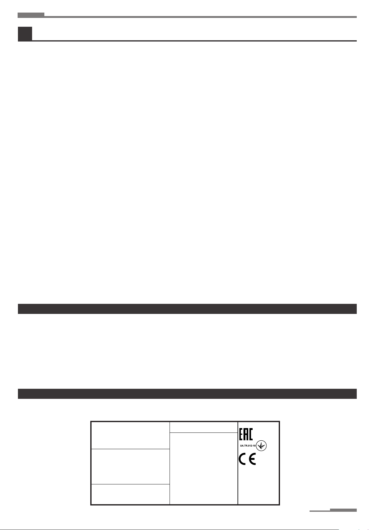
The appliance is equipped with data board, which is placed on inside of device’s door� On this data board there are information concern-
1. picture: Data board
2.
II2H3P
PAKOLE Trade Kft.
8000 Székesfehérvár,
Börgöndi út 8-10.
Pconnecting min.:
20 mbar
437 W
Category:
Electrical power:
30 Pa
Stat. air pressure:
5010 m³/h
Manufacturer
Type
Nominal input:
47,3 kW
Naturalgas
Pconnecting max.:
51-7445-1
Series number:
GB
Targeted country:
Gas type:
Electrical protection:
Electrical connection:
Max.current entry:
IP20
AC 230V 50Hz
Dat e/place of produc tion
21.08.2019
60 mbar
2,8 A
Airflow:
Jet pressure:
7 mbar
GTV-48A
NOx
4
PIN:
1008 CQ 2928
1008 18

6
GTV FORCED CONVECTION AIR HEATERS Instructions for Installation and Servicing
WARNING! Do not use the appliance in such place where corrosive materials can be in the air!
If the appliance has to be applied in this circumstances outside air has to be ensured for combustion
air and circulation as well („CL” type)!
The manufacturer can not assume responsibility for fault of equipment in case the installation is not happened according to the above�
ask our colleague for help
materials, halo hydrocarbons etc�), and with knowledge of these materials must be planed the heater system!
-
Installation must be carried out always strictly complying with the current standards of the
country where the appliance is going to be used and following, of course, the instructions given by the
producer�
trained personnel only�
-
-
tions�
According to the installation project, install the electric power lines�
Always make sure that the unit and all its electrical parts have been cor-
rectly earthed prior starting up the unit�
If you have to disassemble the unit, use special protective gloves�
Beware of sharp edges inside the unit!
Beware of roof corners of outdoor units!
Keep suction grids always clear!
Before cleaning or maintaining the unit, make sure that all electrical parts
and cannot be inadvertently started prior to opening inspection panels�
Fans can reach a speed of 1000 rpm� Do not insert any object nor hands
in the electric fan�
We recommend to install a safety switch which can be easily reached to
-
Before opening the unit, make sure that all electrical parts have been
-
vertently started prior to opening inspection panels�
Should the unit work in a house where disabled people and/or children live, it must be placed safely away from their
reach� Always make sure that the access door to the inside control board stay locked�
An incorrect installation can cause damages to people, animals and property� In case of erroneous installation, the
manufacturer cannot be held responsible for such damages�
• The manufacturer cannot be held responsible for such damages by improper uses, errate uses, etc�
CAUTION
DANGER
CAUTION
ELECTRIC
SUPPLY
CAUTION
DANGEROUS
OPERATION
CAUTION
HIGH
TEMPERATURE
CAUTION
DISCONNECT
POWER LINE
ATTENTION
COMPULSORY:
EARTHING
ATTENTION
THE USAGE OF
MOVING EQUIPMENT
IS COMPULSORY
ATTENTION
COMPULSORY:
USE PROTECTIVE
GLOVES
ATTENTION
ONLY
QUALIFIED
PERSON
ATTENTION
FORBIDDEN !
CAUTION
DANGER
ATTENTION
ONLY
QUALIFIED
PERSON
CAUTION
DANGER
CAUTION
DANGER
CAUTION
DANGER
CAUTION
DANGER
CAUTION
DANGER
CAUTION
ELECTRIC
SUPPLY
CAUTION
ELECTRIC
SUPPLY
ATTENTION
COMPULSORY:
EARTHING
ATTENTION
COMPULSORY:
EARTHING
ATTENTION
ONLY
QUALIFIED
PERSON
ATTENTION
ONLY
QUALIFIED
PERSON
ATTENTION
COMPULSORY:
USE PROTECTIVE
GLOVES
CAUTION
DANGEROUS
OPERATION
ATTENTION
FORBIDDEN !
CAUTION
DISCONNECT
POWER LINE

7
GTV FORCED CONVECTION AIR HEATERS Instructions for Installation and Servicing
Never use the unit to support other equipment�
Never leave tools, spare parts, etc� inside the unit�
Make sure that all inspection panels are closed properly�
harm to anyone in any way�
The delivery must be made according to the following:
The package must be carefully secured in the loading space�
The package must be transferred in a closed space (always keep packing parts away environmental impacts)�
The unit has a special safety packing for transport and delivery which must be kept in good conditions till the unit is positioned
on the installation place�
Check if there are any damages and if the unit abbreviation is the same as the one of the ordered model�
Every unit is factory tested before shipment, therefore, if there are damages, report them immediately to the carrier�
Transporting, unloading and moving is a process which must be made carefully to avoid any kind of damages� Try not to use the unit’s
The device is placed in cardboard box, one-way pallets are delivered�
Unpacking process:
side of pallet hereby the device can be removed from pallet�
do not remove the protection caps from device and gas installing set until the gas attachment
investigate the device if it is not damaged during the transportation
if it is damaged in that case notify the retailer from whom the device was bought!
There is an envelope inside the unit containing the Instructions for Installation and Servicing, User’s Guide use and Guarantee and ser-
vices and the warranty documents�
The appliance operates based on direct heater principle, that means the heater air is blowed into the heated room directly for assuring of
requested temperature� Besides HEATING (winter) mode the appliance can achieves the VENTILATION of room as well (summer mode)�
Principle: The warm air blower appliance burns up the sucked mixture of combustion air and gas (S-, L-, propane or natural gas), in this
way making the heater air,which is blowed into the heated room (by direct blowing or through air duct) in order to ensure the keeping of
temperature on requested value�
The heating and consumption values to be found as per appliance and gas types in the enclosure 1�b�
The supply of combustion air of appliance can be realized in two ways:
directly from the heated place (A,C)
from open air (CL), it can be used in case of such plants, which are working with dangers materials as follows: painting work-
shops and workshops,which are using explosive or corrosive materials etc…
fan circulates the sucked inside or outside air through the heat exchanger assuring the needed warm air for heating� (the heater air is
average 50°C)
The air supply of blower fan can be solved in two ways:
by direct sucking in from the heated place (A, C, CL types),
by sacking in from outside (CL type)�
The made warm air can be passed into the heated place in two ways:
by direct blowing in through the leading lamellas (A, C types),
by blowing in and leading through air duct to the demanded places (in this case there are no lamellas on the device)�Such as
the C and CL type of GTV�
The technical data of appliance can be found in the enclosure 1�
3.
4.
ATTENTION
THE USAGE OF
MOVING EQUIPMENT
IS COMPULSORY
ATTENTION
ONLY
QUALIFIED
PERSON
ATTENTION
FORBIDDEN !
CAUTION
DANGER
ATTENTION
FORBIDDEN !
ATTENTION
ONLY
QUALIFIED
PERSON

8
GTV FORCED CONVECTION AIR HEATERS Instructions for Installation and Servicing
Heat exchanger
Isolation
Temperature
limiter
Exhaust
chamber
Flue gasket
Magnetic valve
pressure switch
Electronic
controller
Partition
plate
Dual thermostat
Exhaust gas
narrowing
Exhaust fan
Control panel
Burning head
Gas pipe
2. pictures: Inside structure of appliance

9
GTV FORCED CONVECTION AIR HEATERS Instructions for Installation and Servicing
3. picture: Outside structure of appliance
4. picture: Main components of appliance
Air leading
Device side
sheet
Air leading
lamella
Device bottom
cover
Air leading
Device door
Combustion air
connection
Axial or centrifugal blower
fan Flue connec-
tion
Device cover
Blower fan
Flue con-
nection
Combustion air
connection
Gas connection
-
sure switch
Panel-board
Control
lamps
Automatic
burner control
/ gas bloc
Air leading
lamellas
Exhaust fan
Exhaust gas
narrowing
Mounted
burner head

10
GTV FORCED CONVECTION AIR HEATERS Instructions for Installation and Servicing
The overall dimension of appliances are in enclosure 2�
Features:
suction in of heater air is executed from the heated place, it can not be connected to air duct
owing in of warm air is executed directly through the air leading lamellas
Features:
suction in of heater air is executed from the heated place,
blowing in of warm air is executed directly through the air leading lamellas or through the attached air duct to the demanded
places
5. picture: Axial fan-type warm air blower
6. picture: Centrifugal fan-type with lamella execution
Features:
suction in of heater air can be from inside or outside respectively in case of installed „winter-summer” mode relay the suction
in of mixed inside-outside air is executed through air duct
blowing in of warm air is executed through the attached air duct system to the demanded places
7/a. picture: Centrifugal fan-type with air duct execution

11
GTV FORCED CONVECTION AIR HEATERS Instructions for Installation and Servicing
7/b. picture: Air duct execution at „CL” type
installaon is possible,
the mounting of appliance can be executed by cantilever respectively suspension
the appliance has to be placed in that way that its every part be accessible�
The nominal values of gas-supply pressure:
regulator is indispensable because the max. allowed pressure of double-closed magnetic valve is:
The pressure regulator can be installed before each appliance or centrally namely one piece into the gas-supply pipe� In case of unique
solution - namely there is pressure regulator before each appliance – before every pressure regulator, in case of centrally mounted
pressure regulator before pressure regulator and each appliance to be able to avoid the blocking
of appliance’s gas magnetic valves, which can be caused by possible contamination settled in the supply pipes�( despite blowing out of
pipes it can be present)
The connection to the gas-supply pipe must be from above or side (Pic� 8) because in case of bottom connection the possible contamina-
Appropriate connection Incorrect connection
8. picture: Connection to gas-supply pipe
5.

12
GTV FORCED CONVECTION AIR HEATERS Instructions for Installation and Servicing
Gázszűrő
Tömítőgyűrű
Gáz elzáró-szerelvény
Flexibilis gáztömlő
9. picture: Attachment with exible gas pipe
Works to be performed during gas connection
Gas pipes clearing
The thorough clearing of gas-supply system is very important before attachment of appliance�
-
ing and assembling!
Gas lter Gasket ring
Gas shut -o valve
Flexible gas pipe
(mm)
20 - 58 1/2”
68 - 116 3/4”
Before connecting the appliance to the gas pipe line, please disconnect it from the power line and
close the gas valve front of the burner. The appliance must be connected to a grounded power sup-
ply system!
If the above instructions are not followed that can lead to death, heavy injuries or property damages!
FIGYELEM
!
FÖLDELÉS
KIALAKÍTÁSA
SZÜKSÉGES
CAUTION
!
DANGER
!
CAUTION
!
ELECTRIC
SUPPLY
The suitable safe operation can not be performed, unless all safety regulations are kept and the equipment properly earthed�
Whenever an electrical connection is made always the earthing wire should be the longest even in case of cable over stretching the
earthing should brake last�
Choosing the right size of cable the maximum amperage, the local regulations and the fact that more than 3% voltage drop is not al-
lowed need to be taken into account�
Use H05V-K or N07V-K insulated cable suitable for 300/500V�
All cables need to be lied into a wire tube or channel�
Cables coming out from the wire tube or channel should not be in tension or twisted� Cables always need to be protected from the
humidity� Left cables must only be used for connecting the end section� Check all cable connections�

13
GTV FORCED CONVECTION AIR HEATERS Instructions for Installation and Servicing
11
4
3
2
1
6
7
5
9
10
8
12
Push m an
Pull a uto
Piros Zöld
O
N
C
C
N
C
Nfv
FAN LIMIT
40
20
100
120
60
80
°C
Füstgáz
ventilátor
Lfv
Axiál ventilátor
NL
N
V
L
11
4
3
2
1
7
5
9
10
12
25
24
23
22
21
20
19
18
17
16
15
14
1332
31
30
L
N
L
1
Burkolat
.
.
.
26
REJTS EL!
Mágnesszelep: VK4125C1007
Elektronika: Honeywell S4565C3090B060
HONEYWELL
Mágnesszelep
Connect the heater electrically according to the attached drawing�
Electrical connection scheme might be changing: we do recommend using the electrical wir-
ing scheme sent with the product
10. picture: Axiál fan-type electrical connection of GTV appliance with
HONEYWELL control box

14
GTV FORCED CONVECTION AIR HEATERS Instructions for Installation and Servicing
11
4
3
2
1
6
7
5
9
10
8
12
Push m an
Pull a uto
Piros Zöld
O
N
C
C
N
C
Nfv
FAN LIMIT
40
20
100
120
60
80
°C
Füstgáz
ventilátor
Lfv
Axiál ventilátor
NL
N
V
L
11
4
3
2
1
7
5
9
10
12
25
24
23
22
21
20
19
18
17
16
15
14
1332
31
30
L
N
L
1
Burkolat
.
.
.
26
REJTS EL!
Mágnesszelep: 845 SIGMA
840 SIGMA
Elektronika: SIT 579 DBC (405)
Mágnesszelep
SIT 579 DBC
11. picture: Axiál fan-type electrical connection of GTV appliance with
SIT control box

15
GTV FORCED CONVECTION AIR HEATERS Instructions for Installation and Servicing
L
N
L
1
11
4
3
2
1
6
7
5
9
10
8
12
Push man
Pull au to
Piros Zöld
O
N
C
C
N
CNfv
FAN LIMIT
40
20
100
120
60
80
°C
Füstgáz
ventilátor
Lfv
N
V
L
11
4
3
2
1
7
5
9
10
12
25
24
23
22
21
20
19
18
17
16
15
14
1332
31
30
N
L
Centrifugál (levegő
áramoltató) ventilátor
13
24
A1
A2
26
Burkolat
.
.
.
REJTS EL!
Mágnesszelep: VK4125C1007
Elektronika: S4565C3090B060
Mágnesszelep
HONEYWELL
12. picture: Centrifugal fan-type electrical connection of GTV appliance with
HONEYWELL control box

16
GTV FORCED CONVECTION AIR HEATERS Instructions for Installation and Servicing
L
N
L
1
Push man
Pull auto
Piros Zöld
O
N
C
C
N
C
Nfv
FAN LIMIT
40
20
100
120
60
80
°C
Füstgáz
ventilátor
Lfv
N
V
L
25
24
23
22
21
20
19
18
17
16
15
14
1332
31
30
N
L
Centrifugál (levegő
áramoltató) ventilátor
1 3
2 4
A1
A2
26
Burkolat
.
.
.
11
4
3
2
1
6
7
5
9
10
8
12
11
4
3
2
1
7
5
9
10
12
REJTS EL!
Mágnesszelep: SIT840 SIGMA
Elektronika: SIT 579 DBC (405 )
Mágnesszelep
SIT 579 DBC
13. picture: Centrifugal fan-type electrical connection of GTV appliance with
SIT control box

17
GTV FORCED CONVECTION AIR HEATERS Instructions for Installation and Servicing
Push man
Pull auto
Piros Zöld
O
N
C
C
N
CNfv
FAN LIMIT
40
20
100
120
60
80
°C
Füstgáz
ventilátor
Lfv
Axiál ventilátor
NL
N
V
L
N
13 14 15 16 17 18 19 20 21 22 23 24 25
11
4
3
2
6
7
5
9
10
8
12
11
4
3
2
1
7
5
9
10
12
1
26
Burkolat
.
.
.
L
N
L1
L2
L2
REJTS EL!
Mágnesszelep: VK4125C1007
V4336A
Elektronika: S4565C30900
Mágnesszelep
HONEYWELL
14. picture: Axial fan-type electrical connection of GTV appliance with
HONEYWELL control box

18
GTV FORCED CONVECTION AIR HEATERS Instructions for Installation and Servicing
AHP3
Push man
Pull auto
Piros Zöld
O
N
C
C
N
C
Nfv
FAN LIMIT
40
20
100
120
60
80
°C
Füstgáz
ventilátor
Lfv
Axiál ventilátor
NL
V
N
L
V
N
L
N
V
L
N
13 14 15 16 17 18 19 20 21 22 23 24 25
11
4
3
2
6
7
5
9
10
8
12
11
4
3
2
1
7
5
9
10
12
1
26
Burkolat
.
.
.
L2
REJTS EL!
Mágnesszelep: VK4125C1007
V4336A
Elektronika: S4565C30900
Mágnesszelep
HONEYWELL
L2
15. picture: Axial fan-type electrical connection of GTV appliance with
HONEYWELL control box

19
GTV FORCED CONVECTION AIR HEATERS Instructions for Installation and Servicing
Push man
Pu ll auto
O
N
C
C
N
C
Nfv
FAN LIM IT
40
20
100
120
60
80
°C
Füstgáz
ventilátor
Lfv
Axiál ventilátor
N
L
N
V
L
1
2
3
4
6
7
9
11
27
28
29
12
13
14
15
16
17
18
19
20
21
C
Piros Zöld
L
N
L
1
1514131211109
8
7654321
JT2JT1
J6J5
.
DUNGS
HONEYWELL
.
Burkolat
BRAHMA CM31
.
A1
A2
13
24
REJTS EL!
Mágnesszelep: VK4605A1096
MBC-120
Elektronika: BRAHMA CM31
Mágnesszelep
16. picture: Axial fan-type electrical connection of GTV appliance with
BRAHMA control box

20
GTV FORCED CONVECTION AIR HEATERS Instructions for Installation and Servicing
PE
NY1
K1
12
11
10
8
1
K2
K3
F4
2A
C4
C1
C2
L
L1
PE
N
V2
ZÖLD
PIROS
APS
Füstgáz ventilátor
ION
Elektronika
Reset
Szelep OUT
Szelep IN
LIMIT TERM
FAN TERM
BIZT. TERM
Készülék burkolatán helyezkednek el
1514131211109
8
7654321
JT2JT1
J6
J5
BRAHMA CM31
DUNGS
HONEYWELL
.
.Burkolat
.
REJTS EL!
Mágnesszelep: VK4605A1096
MBC-120
Elektronika: BRAHMA CM31
Mágnesszelep
17. picture: 2-point regulation ,Axial fan-type electrical connection of GTV appliance with
BRAHMA control box
This manual suits for next models
23
Table of contents
Other Pakole Blower manuals
Popular Blower manuals by other brands

Black & Decker
Black & Decker Leaf Hog 617365-00 instruction manual

Cincinnati Fan
Cincinnati Fan CPF Installation, safety, operation & maintenance manual amd parts list

HAKO
HAKO 980 E/EH instruction manual

Homelite
Homelite ut09526 Operator's manual

EGO
EGO LB4800E Repair Guide Line

Flymo
Flymo SCIROCCO 2200 Original instructions