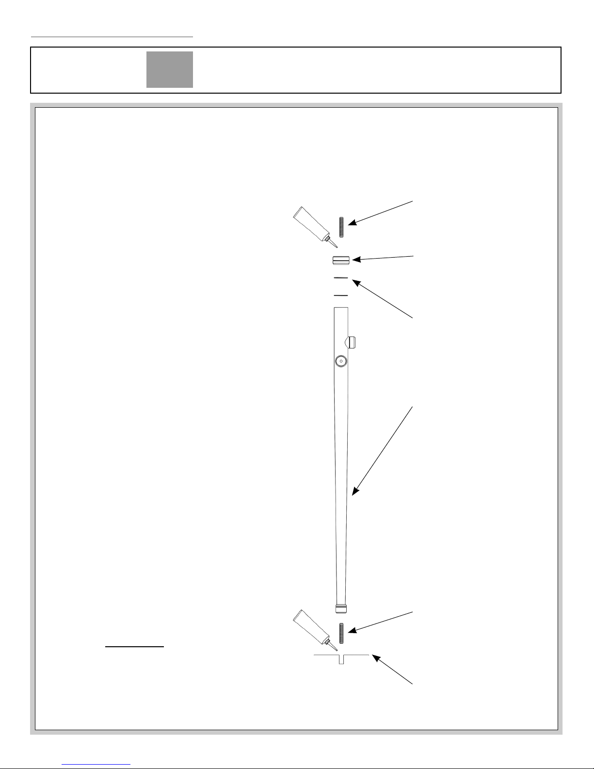
1.5"Tapered Leg Tubing
M
Minimal with 1.0” diameter crossbars
LEG SYSTEM INSTALLATION INSTRUCTIONS
© 2018 Palmer Industries, Inc. Sinklegs.com 401-421-1730 3.
Counter Top Pin
Leg Assembly
Shims:
Add as needed to level
Top Cap
Floor
Floor Pins must engage
1/4”diameter holes
drilled into ooring.
Recommended minimum
hole depth of 1/4”
CUSTOM SINK LEG SOLUTIONS
PALMER
INDUSTRIES
rev: 091718
SEE ADDITIONAL PAGES FOR INSTRUCTIONS SPECIFIC TO INCLUDED OPTIONS.
• Determine that you have received the
correct product before unpacking and
unwrapping the leg system components.
• The leg system components must be
protected from abrasion and scratching
during installation. Use padding on the
oor to protect your console during
layout and assembly.
• The Minimal style may be eld cut to
reduce width and depth.
• Verticals must be plumb and horizontals
must be level. Wall Returns and Shelf
Supports must be parallel, and square
to the Horizontal Crossbar. Leg heights
may need to be shimmed to achieve a
level counter top.
• Leg assemblies must be positioned so
that the set screw holes face toward
the back wall and Wall Flanges must be
rotated so that the set screw holes are
not visible from a standing position in
front of the vanity.
• Wall bracket must be secured solidly to
the wall to bear the weight of the
counter top.
• Front Legs MUST be pinned to the oor
to prevent lateral movement.
• The counter top must be attached to
the tops of the legs and the wall bracket
with silicone adhesive. Conrm that the
installation is correct and complete and
that the shelf, if included, ts properly
before permanently gluing the counter
top into place.
INSTALLATION
INSTRUCTIONS
rev: 111918