MaintenancescheduleofHigh-Tro-Reelunit
Pleasecheckbythemaintenancetablebasedonthismaintenanceschedule.
Refertothemaintenancetableforaconcretecheckitem.
Atintroduction The5thyear The10thyear
Maintenancedonebytheelectricalworktrader.
The product-life is different in use conditions and the service space, however, It is possible to use it for about t 10 years
by regularly maintaining and the regular service in correct construction.
・Checkthepresenceofremarkabledirtofthesurfaceoftheconductor.
(Onceevery3to6months)→Cleanitwiththecottonwasteetc.
・ChecktheTro-Reelunitdoesn'tbecomeitinazigzagline.
(Onceevery3to6months)→Reviewthesizebetweenconductorsinthejoint.
・ChecktheTro-Reelunitisnotawayfromthehanger.
(Onceevery3to6months)→InstalltheTro-Reelunitonthehanger.
・
Checkwhetherthereisnot crackand alackoftheinsulationsheath
(Onceevery3to6months)
→ProductexchangerecommendationthatexchangestheTro-Reelunit.
High-Tro-Reel
・Checkwhetherthereislooseningofthefixationscrewortheterminalscrew.
(Onceevery3to6months)→Retighten.
・
Checkwhethertheresinhasnotbeendamaged.(Onceevery3to6months)
→Exchangeproducts.
Joiner
Centerfeed-injoiner
・
Checkwhetherthereislooseningofthenut.(Onceevery3to6months)→Retighten.
・
Checkwhethertheresinhasnotbeendamaged.(Onceevery3to6months)
→Exchangeproducts.
Hanger
Guidecap
Insulatingpiece
・
Checkwhetherthereislooseningofthebolt.(Onceevery1to3months)→Retighten.
・
Checkwhetherwearhasreachedthereplacementline.(Onceevery1to3months)
→Exchangethecollector,whenwornouttothereplacementline.
・
Checkdamageofspringpinandrotationaxis,wear-outofmetalfittingsofspringreceiving.
(Onceevery1to3months)→Exchangeproductswhendamageorabnormalityisfound.Pleasekeepnormal.
Collectorarm
Productexchange
recommendation.
Trial run・Periodic inspection
Notes
・For using safely, please inspect the system one month after starting regular operation.
・The inspection cycle is mentioned below. However, determine your own inspection cycle
based on the actual operating rate and environmental condition.
Checktheamountofwearofthecollectorand
conductoroftheduct,replaceitifnecessary.
Don'ttheinsulatedsheathandtheresinpartofcollector
spinningshafttouch?
○
Retighten.
Isthereanyfixedscrewloosen?
○
Adjustitwithinspecifiedsize.
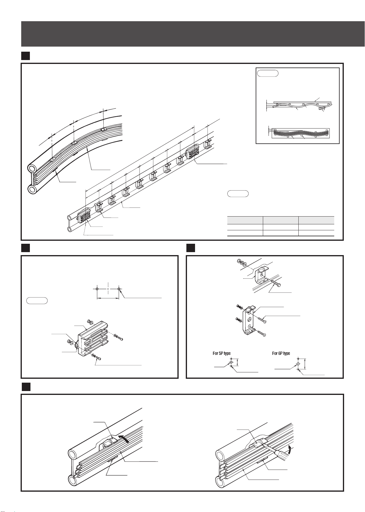
Arecorrectjoinermountingsize?
<Refertoinstallationmanual
>
・Orless·10℃:3003mm
·11℃˜40℃:3000mm
○
Adjusttheproperclearancesize.
・Adjustthelengthoftheduct,orAalignthejoiner.
・Adjustthemountingpositionofthehangers.
Arecorrectclearancesizeofbetweentheconductors?
<Refertoinstallationmanual
>
・Orless·10℃:5〜13mm
・11℃˜40℃:3〜10mm
Whendamageandcrackoccurredinthefixed
endinsulator,pleasechangeit.
Arenottherethecracksanddamagedona
plasticpart?
Ifitexceedsathresholdamountofwear,please
replacethemainconductorIncaseofwearing
downtothereplacementindicationlineatnext
inspection,pleasereplaceearlierthanusual.
Amountofwearoftheconductoriscorrect?
Amountofwearoftheconductor:0.5mmorless
○
Reviewforanydislocatedpositiononthe
unit.Correctifany.
Isnttheunitdislocatedfromthehanger?
<Refertoinstallationmanual
>
○
Correctthetwistingorbendingoftheduct.
※Ifyoucannotfix,replacetheduct.
Isthereasignificanttwistingorbendingoftheduct?
○
Adjustitwithinspecifiedsize.
・Adjustthelengthoftheduct,orAalignthejoiner.
・Adjustthemountingpositionofthehangers.
Whatisthemeanderoftheductorswellintheregulations?
<Refertoinstallationmanual
>
Theserpentinetolerance:standard±5mm
Toleranceofmodulation·:standard±3mm
○
Ifthetipofthesheaththicknessis1.2mm
orless,pleasereplaceinsulation
Istheredamageandcrackattheinsulating
sheath?
Removeanyprotrusion(convex)onthearc
scratchusingafile.
※Ifyoucannotfix,pleasereplacetheduct.
scratchusingafile.
Isthereanyarkgeneratedprotrusion
(convexshaped)onitsslidingsurface?
Cleanwithaspecificpurposecleaner
orwastecloth.
Checktoseeifthereisanyforeign
particlesadheringonitsslidingsurface
orifitisseriouslycontaminated.
Inspectioncycle(standard)
Measures
Result
※
RemedyContentsofinspection
Name
○:
Exchangerequired
Measures
●:
Finishedwithexchange
△:
Adjustmentrequired
▲:
Finishedwithadjustment
Result
○
:
Normal
×
:
Abnormali
y
Atitle Checkday YDM Thecheck
personincharge
・
Inspections item at the time of the pre-use test run(Checking at periodic inspection).
・
For using safely, please inspect the system one month after starting regular operation.
・The inspection cycle is mentioned below. However, determine your own
inspection cycle based on the actual operating rate and environmental
condition.
・Items in bold: Inspection items requiring particular attention.
Notes
<To Maintenance manager>
Tro-Reelunit
Joiner(Centerfeed-injoiner)
○
Retighten.Isthereanyfixedscrewloosen?
○
Adjustitwithinspecifieddimension.
Arecorrectclearancesizeofbetweentheguidecap?
<Refertoinstallationmanual
>
Isthegapbetweentheguidecapsizecorrect?
・Guidecapmutualclearance:10〜20mm
Horizontal:Max2mm
Vertical:Max2mm
Pleasehavetheaboverange,evenwhen
loadedtoratedloadonthetrolleyatanytime.
Guidecap
Pleaseexchange,whentheamountofwear
ofaguidecapresinpartis0.5mmormore.
Amountofwearoftheplasticiscorrect?
Amountofwearoftheplastic:0.5mmorless
Exchangeofaguideiswhentheconductorsliding
surfaceswillbecometallerthantheguide-capslidingsurfaces,
thenumberoftimesofpassageofthecollectoris5milliontimes
.
○
Whendamageandcrackoccurredinthefixedend
insulator,pleasechangeit.
Arenottherethecracksanddamagedon
aplasticpart?
○
Inserttheducttoensure.
Areinserttheconductorandsheathofaductcertainly?
<Refertoinstallationmanual
>
○
Adjustitwithinspecifiedsize.
Arecorrectcuttingsizeoftheductortheductend?
<Refertoinstallationmanual
>
•TheductcuttingSize:sizeofbetweenJoiner(L)-3mm
※ThesameisthecaseoftheCenterFeed-inJoiner.
・CuttingSizeoftheductend:Removetheinsulating
sheath27.5mmfromtheedgeoftheduct,
○
Retighten.Isthereanyfixedscrewloosen?
○
Adjusttotheproperpitch
Didyousetupthecorrectsizeandmountinghangers?
<Refertoinstallationmanual
>
・Straightsections:Max400mm
・Curvedsection :Max400mm
Joiner
(Centerfeed-injoiner)
Hanger
thenumberof
passesthrough
thecollector's
arm:1,000,000