Introduction
Thank
you
for
purchasing
a
Panamax
MB1500
Uninterruptible
Power
Supply,
and
congratulations
on
your
choice.
The
MB1500
Uninterrupt-
ible
Power
Supply
features
Panamax's
revolutionary
AVM
(Automatic
Voltage
Monitoring)
circuit,
and
our
exclusive
Linear
Filtering
Technol-
ogy
(LiFT).
Together,
these
technologies
comprise
precisely
what
our
customers
have
come
to
expect
from
Panamax
-
uncompromised
AC
protection
and
purification
.
Table
of
Contents
Features
Descriptions,
Important
Safety
Instructions,
Important
Rack
Mounting
Options
.......................
..
..........................................
pg.
1
Front
Panel
Installation
and
Battery
Replacement
...................
.
.................
.
.....
..
....................
...
.......
...
..................................
....
......
pg.
2
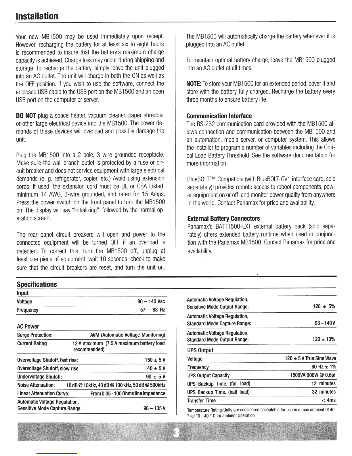
Installation
&
Specifications
.........................
....
....
....................
...
...........................................
..
......
.
..................................
.
..
...
.....
pg.
3
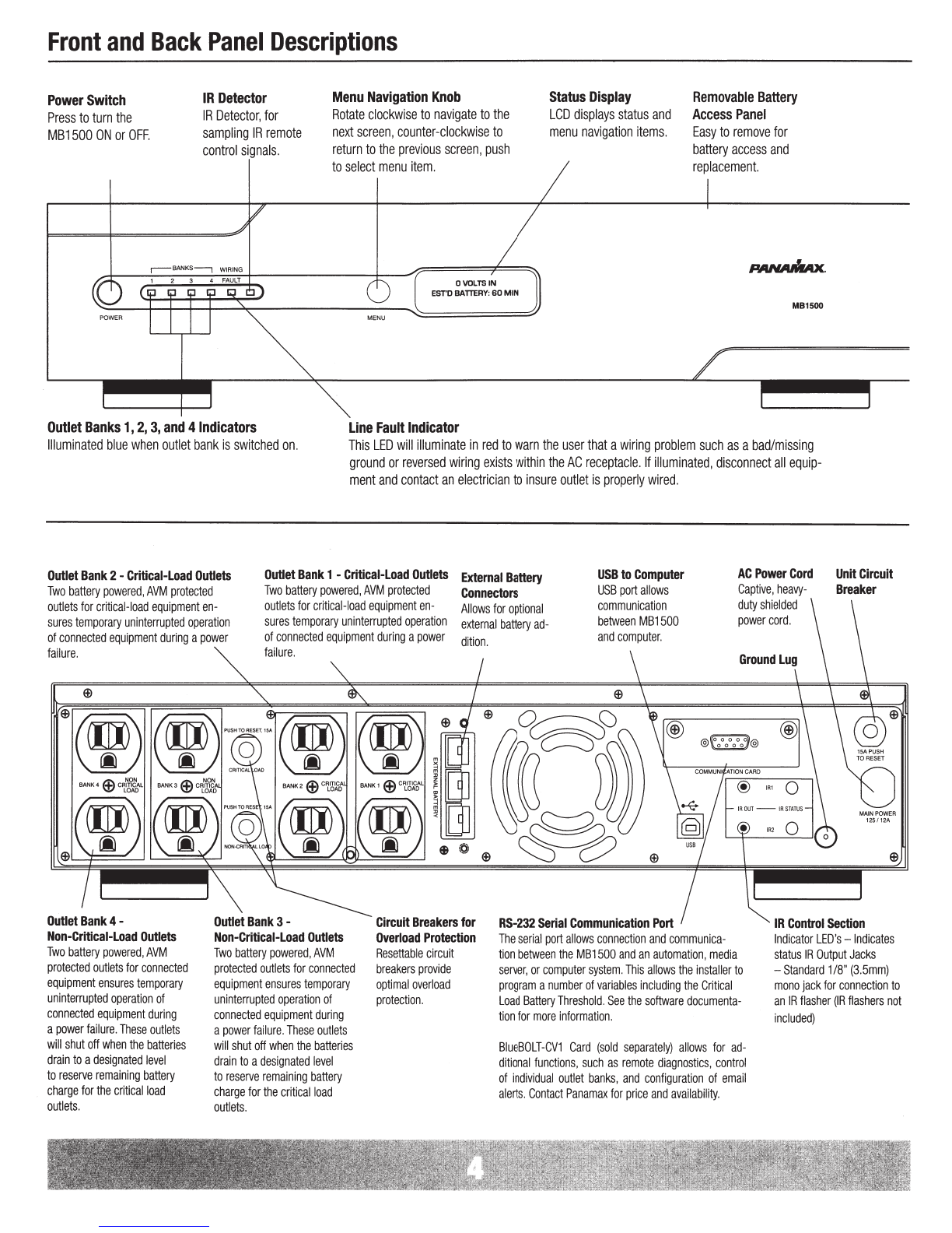
Front
and
Back
Panel
Descriptions
..
..
.
....
.
...
..
...................................
..
..
.....................
...
......................
..
..............................
.
....
...
..
.....
..
.
pg.
4
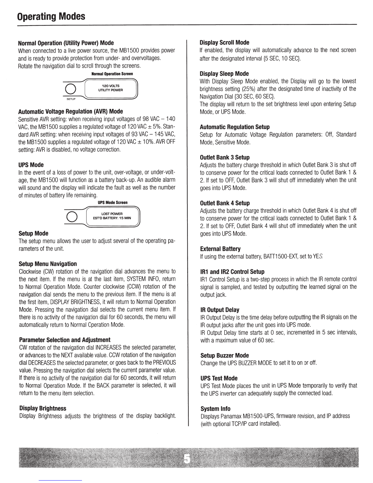
Operating
Modes
...
.
..
.
...............
.
...........
.
..................................
.
................................................
..
............................
.
........
.
..
.
....
.
.......
pg.
5
Advanced
Operation
..............................................
.
............................
.
.......
...
.............
..
...
.
...
..
...
....
.
......
...
.....
...
..
.
.........
.......
..
....
.........
pg.
6
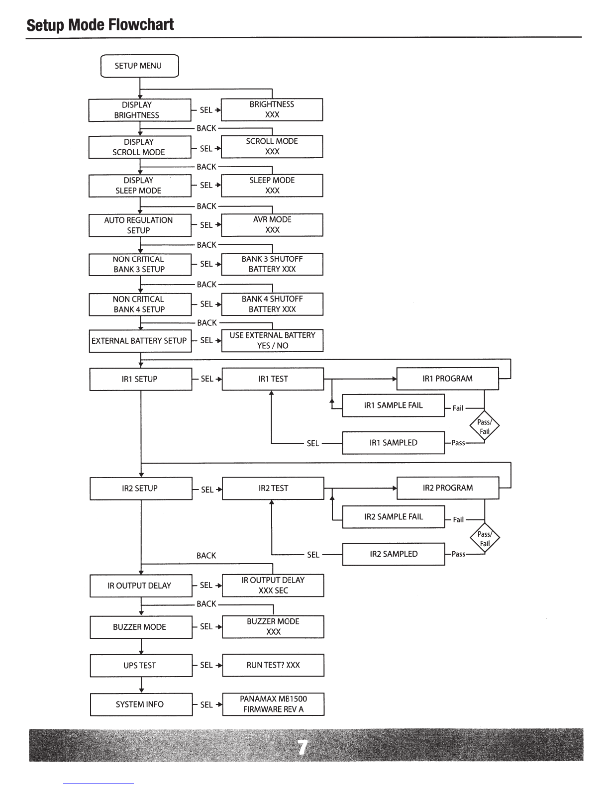
Setup
Mode
Flowchart
...
............
.
.......................
.
..................
...
.............................
.
........................
.
....
.
...........
.
............
.
................
pg.
7
Communications
Protocol
&
Command
Set..
..........................................................
.
..................
.
.......................
.
..
.
.......
pgs.
8,
9,1
0,
11
FCC
Notice,
Contacting
Customer
Service,
Warranty
Information
.
............
.
.....
.
.............................................................................
pg
.12
Before
You
Begin
UNPACKING
Inspect
the
UPS
upon
receipt.
In
addition
to
this
manual
the
box
should
contain
the
following:
1.
UPS
Unit
2.
DB
9
Serial
Cable
3.
Front
Rack
Mounting
Kit
R
ear
R
ack
Mou
nt
ing
Kit
Availa
bl
e
(sold
separate
l
y)
4.
Software
CD
5.
USB
Cord
®
2011
Panamax
LLC,
1690
Corporate
Circle
,
Petaluma,
CA
94954
•
www.panamax.com
•
707-283-5900
•
Fax
707-283-5901


 Plus Startup manual")