CONTENTS
1 OVERVIEW................................................................................................................................................1-1
General ........................................................................................................................................................1-1
System Configurations (Example)................................................................................................................1-1
Specifications...............................................................................................................................................1-2
Memory Map ................................................................................................................................................1-6
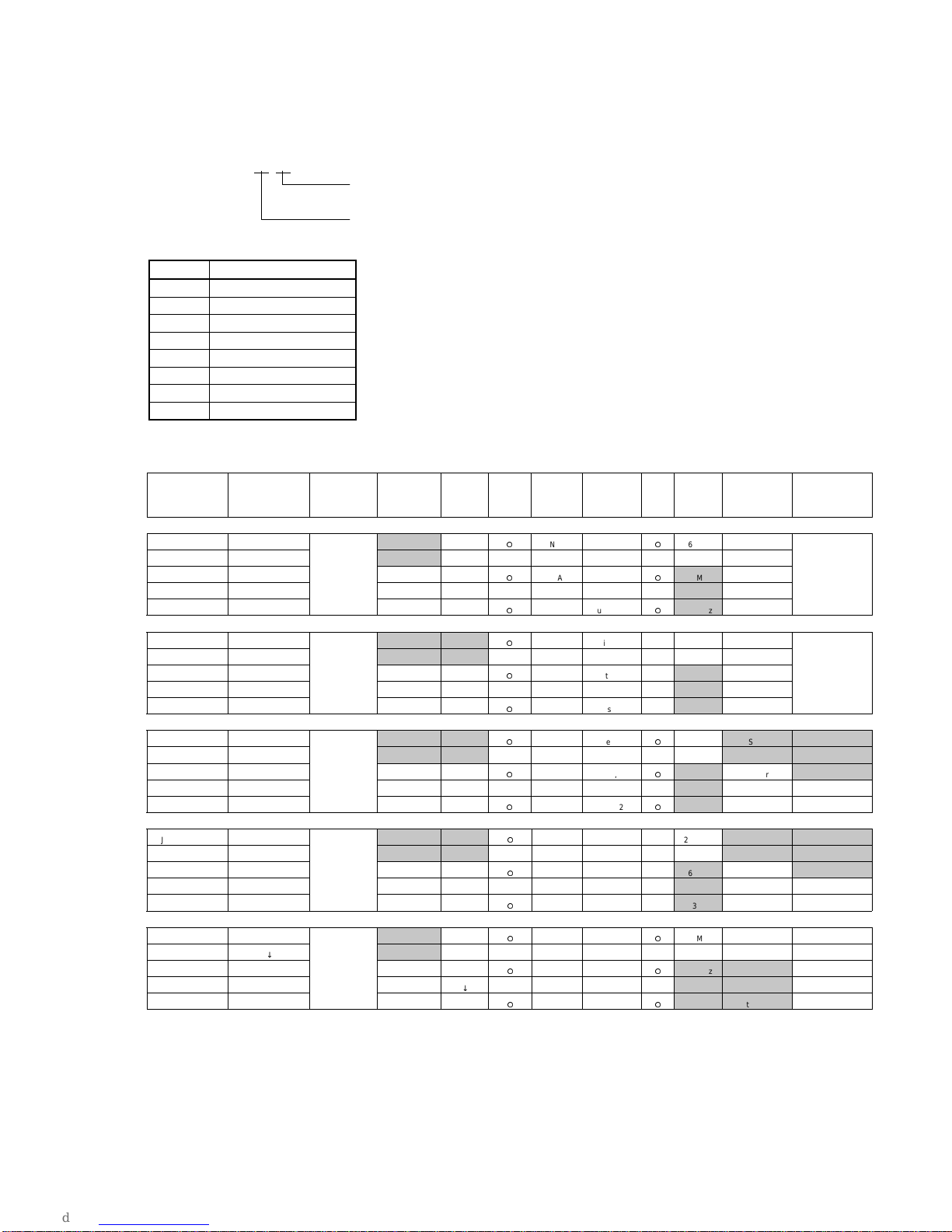
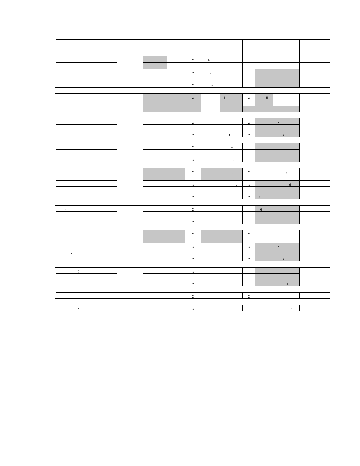
I/O Port Map.................................................................................................................................................1-7
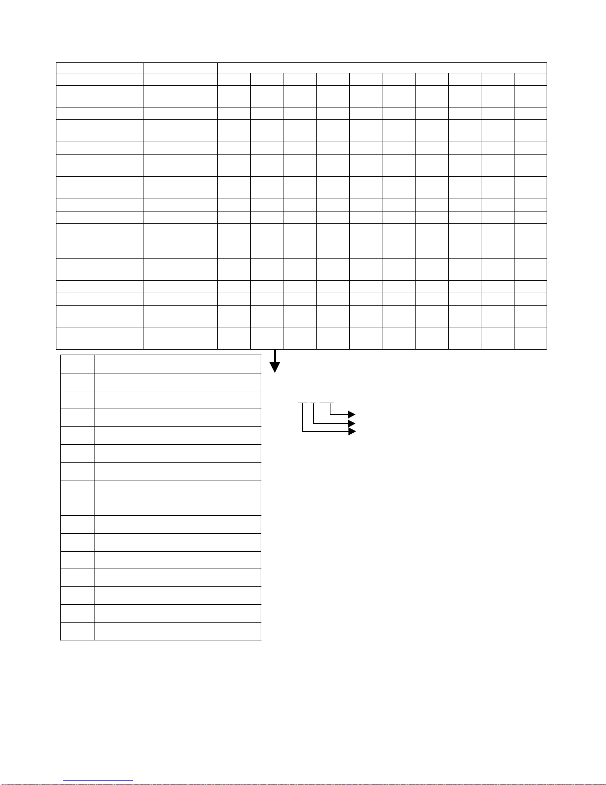
Interrupt Level ..............................................................................................................................................1-8
Pin assignments...........................................................................................................................................1-9
Appendix B : Dip Switches and Jumpers...................................................................................................1-16
2 Description of Operation ............................................................................................................................2-1
JS-170FR Block Diagram ............................................................................................................................2-1
Description of Main PCB Circuits.................................................................................................................2-2
2.1.1 CPU PENTIUM-II 266MHz or 333MHz (Refer to the page 4-1.) ................................................2-2
2.1.2 Chip set FW82443BX, FW82371EB (Refer to the page 4-1 and page 4-3.)..............................2-2
2.1.2.1 FW82371EB Pin Assignment..................................................................................................2-3
2.1.2.2 RTC (Real Time Clock) circuit.................................................................................................2-9
2.1.2.3 IDE interface..........................................................................................................................2-10
2.1.2.4 USB interface.........................................................................................................................2-12
2.1.3 Main RAM circuit.......................................................................................................................2-13
2.1.4 BIOS ROM................................................................................................................................2-14
2.1.5 IT8673F circuit..........................................................................................................................2-15
2.1.5.1 IT8673F Pin Assignment.......................................................................................................2-16
2.1.5.2 Serial port (COM1, 2).............................................................................................................2-18
2.1.5.3 Parallel port interface circuit ..................................................................................................2-20
2.1.5.4 FDD interface circuit..............................................................................................................2-21
2.1.5.5 Keyboard controller circuit.....................................................................................................2-23
2.1.5.6 PS/2 mouse controller circuit.................................................................................................2-25
2.1.6 Serial port (COM3, 4)................................................................................................................2-26
2.1.7 VGA circuit (Refer to the page 4-4.) .........................................................................................2-28
2.1.7.1 SM710 Pin Assignment .........................................................................................................2-29
2.1.7.2 LCD interface circuit (Refer to the page 4-4.)........................................................................2-33
2.1.7.3 Back-Lite control circuit .........................................................................................................2-34
2.1.7.4 CRT interface ........................................................................................................................2-35
2.1.8 Piezoelectric buzzer circuit .......................................................................................................2-36
2.1.9 Hardware reset circuit...............................................................................................................2-37
2.1.10 Clock.........................................................................................................................................2-38