6
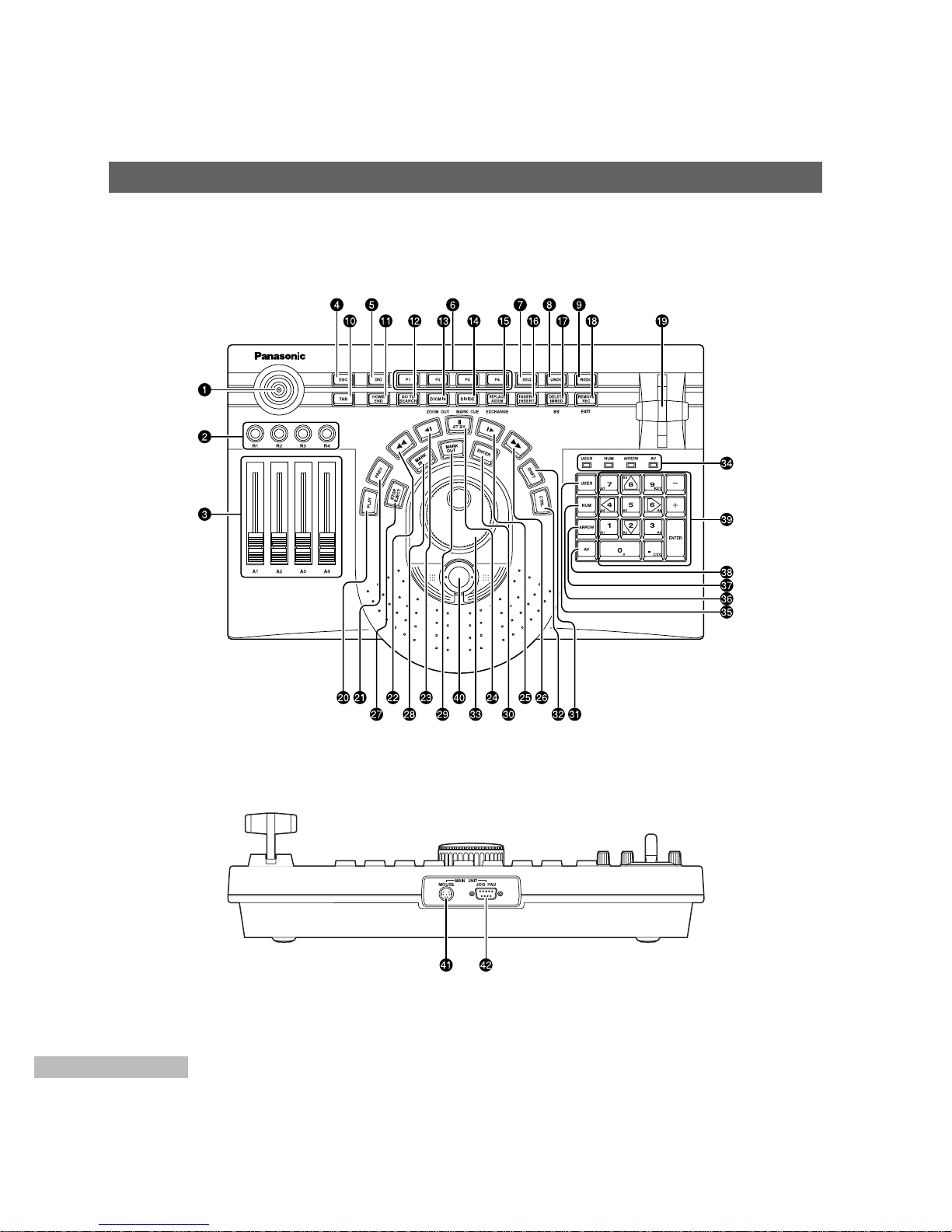
MAJOR OPERATING CONTROLS AND THEIR FUNCTIONS
Used to advance the tape in the external VCR frame
by frame (in the forward direction).
Used to fast forward the tape in the external VCR.
STOP/EJECT
Used to stop play. The external VCR is set to the
stop mode. When it is pressed while “CTRL” is held
down, the tape in the external VCR is ejected.
MARK IN
Used to set the mark in point. When it is pressed
while “SHIFT” is held down, the in point grip can be
selected. When it is pressed while “CTRL” is held
down, the mark in point is deleted.
MARK OUT
Used to set the mark out point. When it is pressed
while “SHIFT” is held down, the out point grip can be
selected. When it is pressed while “CTRL” is held
down, the mark out point is deleted.
ENTER
Used to enter the selected items. With the batch
digitizer, it enters the in and out points.
SHIFT
Used to select the functions of the keys.
CTRL
Used to select the functions of the keys.
Jog/shuttle dial
Jog and shuttle modes are selected (toggle
operation) by pressing down the dial.
In jog mode, the tape is played frame by frame in the
forward direction (when the dial is turned clockwise) or
reverse direction (when it is turned counterclockwise).
In shuttle mode, the tape is played at a variable
speed in the forward direction (when the dial is
turned clockwise) or reverse direction (when it is
turned counterclockwise).
LED
The lighted LED shows the number key mode. The
mode is selected by pressing the “USER”, “NUM”,
“ARROW” and “AV” keys.
USER
Used to switch to the user mode.
In the user mode, the number keys perform the
functions which have been allocated to them.
Frequently used functions can be allocated to the
user keys.
For details on how to allocate these functions, refer
to the operating instructions of the software program
you are using.
NUM
Used to switch to the number input mode.
In the number input mode, the number keys function
as number input keys.
ARROW
Used to switch to the cursor mode.
In the cursor mode, the number keys (2, 4, 6 and 8
keys) function as arrow keys.
AV
Used to switch to the track selection mode.
In the track selection mode, the number keys
function as track selection keys.
For further details on operation, refer to the operating
instructions of the software program you are using.
Number keys
The way in which these keys are used differs
depending on the mode (“USER”, “NUM”, “ARROW”
and “AV”). The “+” and “–” keys are used to
advance the images frame by frame.
The ENTER key enters the selected item.
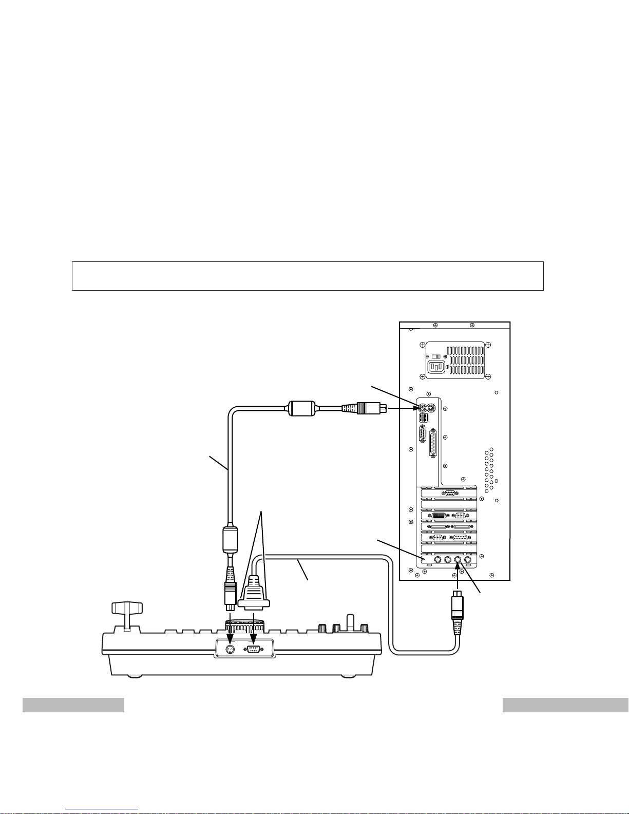
Trackball
This can perform the same operations as those of a
mouse.
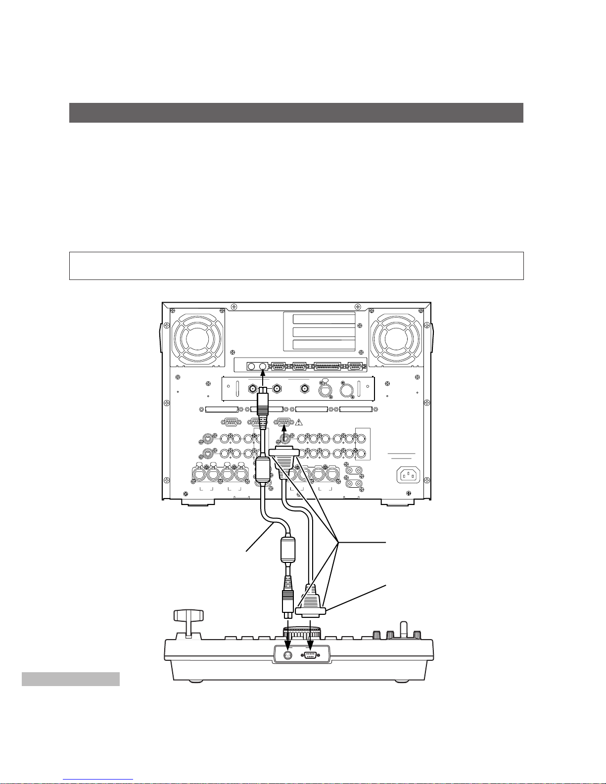
Connect the trackball cable following the instructions
in Connections.
[MOUSE] connector
The trackball cable (supplied accessory) is
connected to this connector.
[JOGPAD] connector
The jog pad cable (VCR/JOGPAD cable) is
connected to this connector.