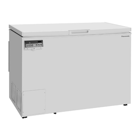
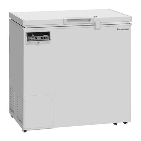
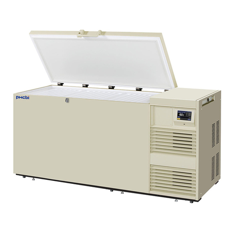
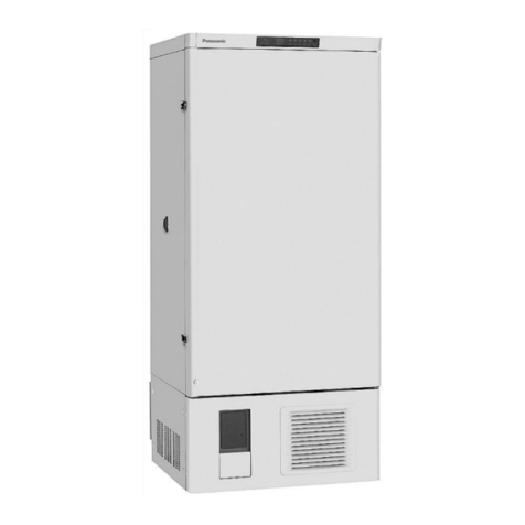
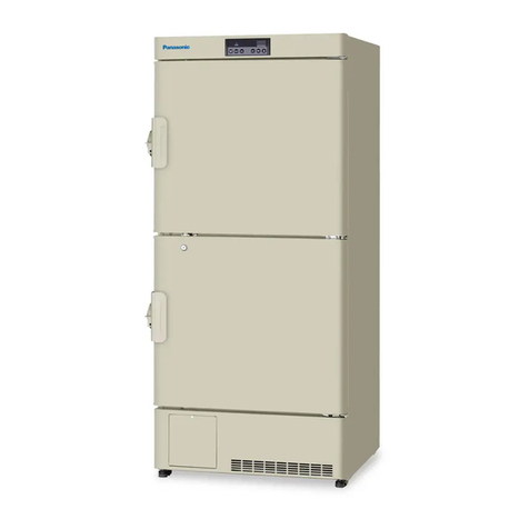
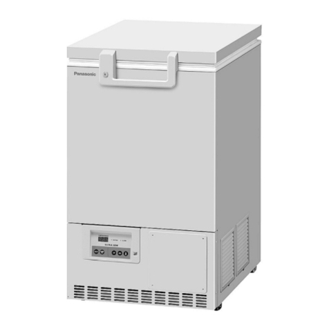
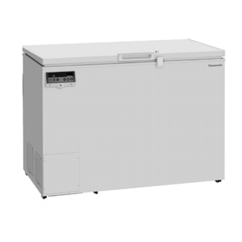
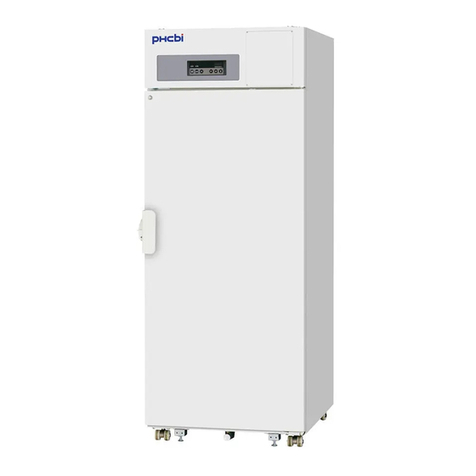
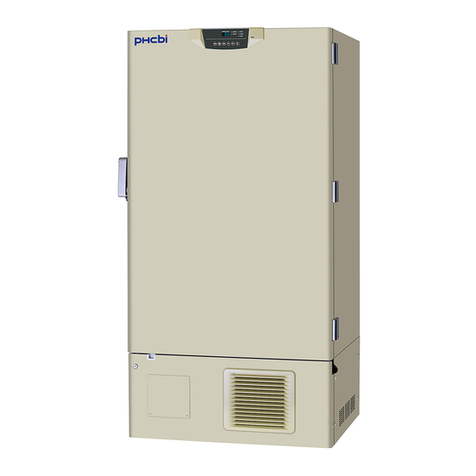
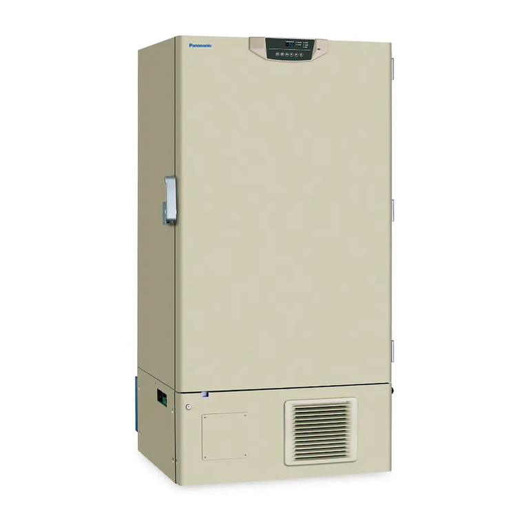
FREEZER COMPONENTS
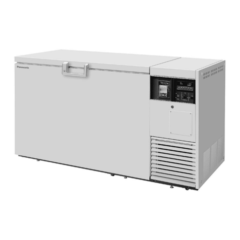
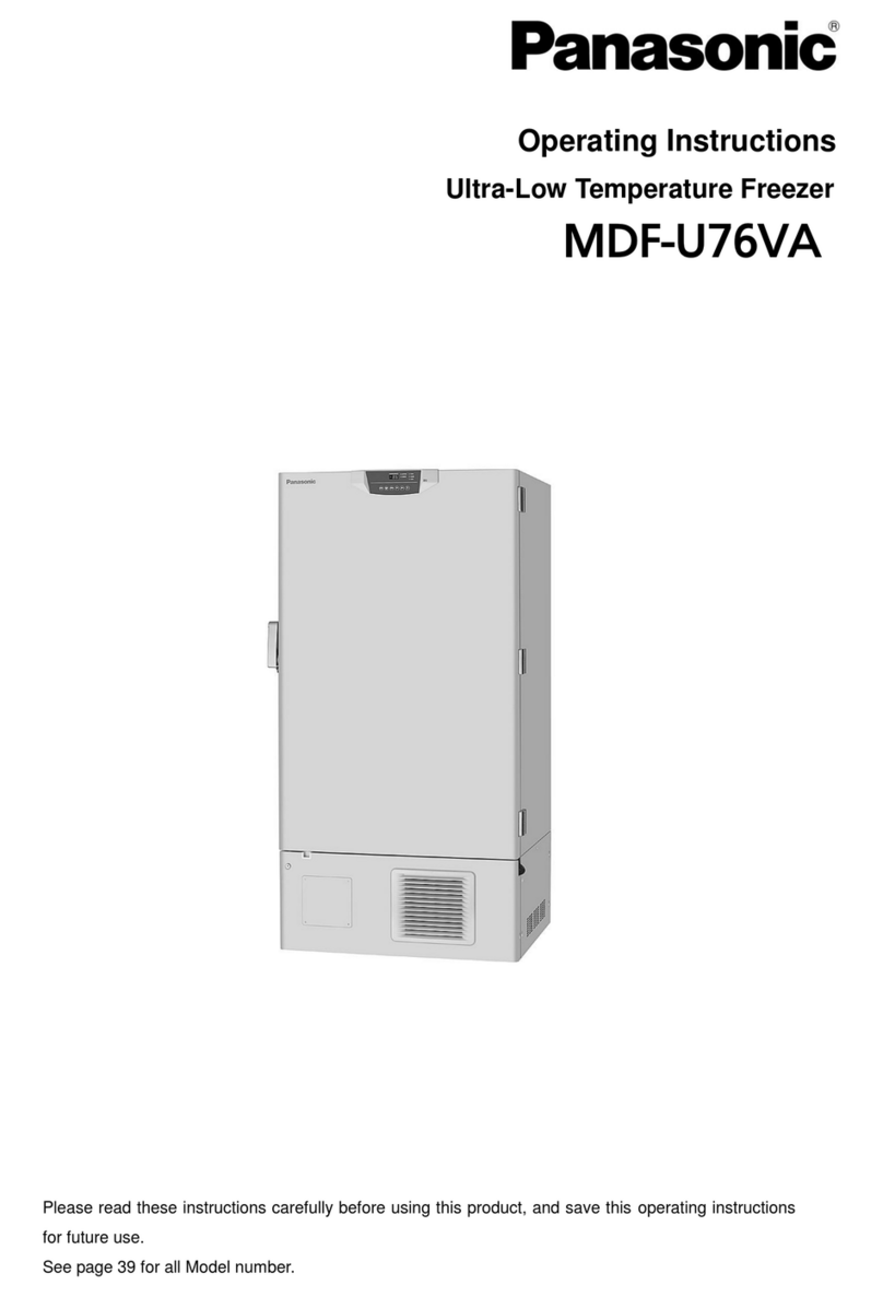
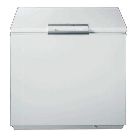
1. Control panel (on the upper front of the outer door): Us d for t mp ratur s tting and indication
of op rating status is display d on th pan l. S pag 10 for d tails.
2. Outer door: To op n th door, grip th handl . On closing, lock th out r door latch compl t ly.
3. Inner door: Th op ration of th inn r door should b quick to minimiz th t mp ratur ris in
chamb r. Lock th inn r door latch compl t ly wh n th inn r door is clos d. Th inn r door is
r movabl for cl aning or d frosting. S pag 23 “Routin maint nanc ”.
4. Outer door latch: Always lock th latch wh n th out r door is clos d.
5. Inner door latch: Always lock th inn r door latch wh n th inn r door is clos d.
6. Magnetic door gasket: This provid s a tight door s al and pr v nts cold air l ak. K p cl an.
7. Access port (rear and bottom): This is us d for l ading a cabl and s nsor of a m asuring
quipm nt, or nozzl of back up cooling kit to chamb r.
8. Air intake vent (grille): Do not block this v nt to k p th prop r cooling p rformanc .
9. Caster: Four cast rs ar provid d to facilitat moving of th cabin t. For th installation, adjust th
l v ling foot so that th front two cast rs cannot contact with th floor.
10. Leveling foot: Th h ight of th fr z r can b adjust d by this scr w typ foot. K p th unit in
l v l at th installation.
11. Condenser filter (behind the grille): This filt r pr v nts th dust from accumulating on th
cond ns r. Th dusty cond ns r filt r may caus failur of r frig rating d vic . Cl an th cond ns r
filt r onc a month. S pag 22 “Routin maint nanc ” for th cl aning.
12. Space for temperature recorder: An automatic t mp ratur r cord r (optional compon nt) can b
attach d h r . S pag 32“ T mp ratur r cord r (Option)”.
13. Ke lock: Turn clockwis to 180
o
with a k y and th out r door is s cur ly lock d.
14. Air intake port: Aft r closing th out r door, if us d to op n soon. S pag 11
B sur to clos th cap of th air intak port aft r th us .
* R plac th cap wh n th air intak port is not us d. Improp r r plac m nt may caus ris of
chamb r t mp ratur or cond nsation around th air intak port.
15. Fixture (on back side): Two fixtur s ar provid d as spac rs b tw n th cabin t and wall and also
s rv as hooks to fix th unit. S pag 13 “Installation”.
16. Power switch: This is for turning ON/OFF th pow r to th unit. ON – “I” OFF – “○”
17. Remote alarm terminal: This is us d to notic an alarm condition of th unit to r mot location.
R f r to pag 11 “R mot alarm t rminal”.
18. Batter switch: This is a switch for a batt ry for pow r failur alarm. Normally, turn on this switch.
B sur to turn off this switch if th fr z r is not in op rating for th long p riod (ov r on month).
19. Fuse: AC 250 V, 5 A is attach d.
WARNING
Fix th sh lf supports and sh lv s s cur ly. Incompl t installation may caus injury or damag .
N v r touch th storag it ms with w t hands. Touching with th w t hands may caus frostbit .
R plac th cap wh n th air intak port is not us d. Improp r r plac m nt may caus ris of chamb r
t mp ratur or cond nsation around th air intak port.
