manuals.online logo
Brands
  1. Home
  2. •
  3. Brands
  4. •
  5. Panasonic
  6. •
  7. Microwave Oven
  8. •
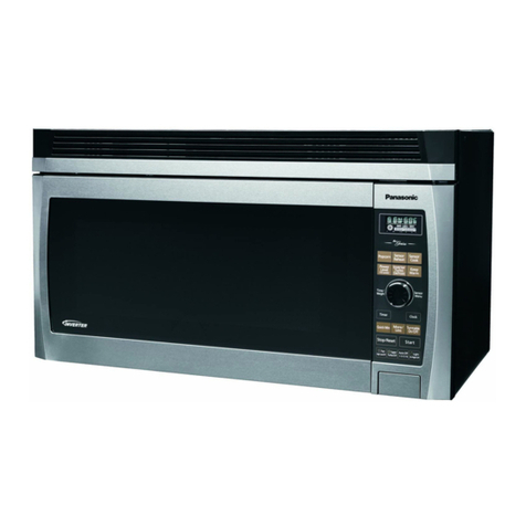
  9. Panasonic NN-8508 User manual

Panasonic NN-8508 User manual

This manual suits for next models

4

Other Panasonic Microwave Oven manuals

Panasonic NN-CD87KS User manual

Panasonic

Panasonic NN-CD87KS User manual

Panasonic NN-GT370M User manual

Panasonic

Panasonic NN-GT370M User manual

Panasonic NN-S451 User manual

Panasonic

Panasonic NN-S451 User manual

Panasonic NN-Q543 User manual

Panasonic

Panasonic NN-Q543 User manual

Panasonic NN-ST680S Use and care manual

Panasonic

Panasonic NN-ST680S Use and care manual

Panasonic NN-SN657S User manual

Panasonic

Panasonic NN-SN657S User manual

Panasonic NN-CD557 Product guide

Panasonic

Panasonic NN-CD557 Product guide

Panasonic Sonic Steamer NE-2180 User manual

Panasonic

Panasonic Sonic Steamer NE-2180 User manual

Panasonic Inverter NNA883 User manual

Panasonic

Panasonic Inverter NNA883 User manual

Panasonic NE-1027 User manual

Panasonic

Panasonic NE-1027 User manual

Panasonic NE-661 User manual

Panasonic

Panasonic NE-661 User manual

Panasonic NN-GD452W User manual

Panasonic

Panasonic NN-GD452W User manual

Panasonic NN-SD786S User manual

Panasonic

Panasonic NN-SD786S User manual

Panasonic NN-CD87 Operating instructions

Panasonic

Panasonic NN-CD87 Operating instructions

Panasonic NN-GF574S User manual

Panasonic

Panasonic NN-GF574S User manual

Panasonic NN-S989BA User manual

Panasonic

Panasonic NN-S989BA User manual

Panasonic Genius NN-SD767S User manual

Panasonic

Panasonic Genius NN-SD767S User manual

Panasonic NN-SG656S CTH User manual

Panasonic

Panasonic NN-SG656S CTH User manual

Panasonic NE-1024F User manual

Panasonic

Panasonic NE-1024F User manual

Panasonic NN-G335WF User manual

Panasonic

Panasonic NN-G335WF User manual

Panasonic Combi Wave NE-C1153 User manual

Panasonic

Panasonic Combi Wave NE-C1153 User manual

Panasonic NN-SM330W Operating instructions

Panasonic

Panasonic NN-SM330W Operating instructions

Panasonic NN-SU64LB User manual

Panasonic

Panasonic NN-SU64LB User manual

Panasonic Sonic Steamer NE-3280 User manual

Panasonic

Panasonic Sonic Steamer NE-3280 User manual

Popular Microwave Oven manuals by other brands

Sharp R-390D manual

Sharp

Sharp R-390D manual

PROFILO MD1000 instruction manual

PROFILO

PROFILO MD1000 instruction manual

Candy MIC 201 EX User instructions

Candy

Candy MIC 201 EX User instructions

PITSOS GMW3101B user manual

PITSOS

PITSOS GMW3101B user manual

Sears 5648744780 Use & care manual

Sears

Sears 5648744780 Use & care manual

BOMANN CB 1272 Instruction manual & guarantee

BOMANN

BOMANN CB 1272 Instruction manual & guarantee

Conrad Electronic 2372935 operating instructions

Conrad Electronic

Conrad Electronic 2372935 operating instructions

GE Spacemaker JVM1440BH datasheet

GE

GE Spacemaker JVM1440BH datasheet

DAEWOO ELECTRONICS KOR-6L8K5S83 Operating instructions & cook book

DAEWOO ELECTRONICS

DAEWOO ELECTRONICS KOR-6L8K5S83 Operating instructions & cook book

DAEWOO ELECTRONICS KOR-1N5A9S Operating instructions & cook book

DAEWOO ELECTRONICS

DAEWOO ELECTRONICS KOR-1N5A9S Operating instructions & cook book

Daewoo KQG-6617G Operating instructions & cook book

Daewoo

Daewoo KQG-6617G Operating instructions & cook book

Samsung M1779 Owner's instructions

Samsung

Samsung M1779 Owner's instructions

GE JES1143 Use and care & cooking guide

GE

GE JES1143 Use and care & cooking guide

Miele H6200BM(TB) Operating and installation instructions

Miele

Miele H6200BM(TB) Operating and installation instructions

Jocel JMO011480 instruction manual

Jocel

Jocel JMO011480 instruction manual

Sharp R-752M Operation manual with cookbook

Sharp

Sharp R-752M Operation manual with cookbook

Electrolux EVL8E00X user manual

Electrolux

Electrolux EVL8E00X user manual

STOVES Q900GRF DO User, installation & servicing instructions

STOVES

STOVES Q900GRF DO User, installation & servicing instructions

manuals.online logo
manuals.online logoBrands
  • About & Mission
  • Contact us
  • Privacy Policy
  • Terms and Conditions

Copyright 2025 Manuals.Online. All Rights Reserved.

ORDER
NO.
MOD88090
ual
Microwave
Oven
NN-8508,
NN-8558
NN-8808,
NN-8858
NN-8808P
Specifications
Power
Source
:
120
V
AC
Single
Phase
60
Hz
(50/60
Hz
for
NN-8808P
only)
Power
Requirement
:
1,400
W
(12.2
A)-----
Microwave
1,500
W
(12.5
A):
Bake
and
Broil
Output
:
700
W:-:--:Full
Microwave
Power
1,400
W::--:-
Heater
|
Microwave
Frequency
:
2,450
MHz
Timer
:
99
Min.
99
Sec./9
Hr.
99
Min.
Outside
Dimensions
:
22”
(W)
X
17-1/4”
(D)
X
15-3/16”
(H)
558
mm
(W)
X
439
mm
(D)
X
385
mm
(H)
Oven
Cavity
Dimensions
:
14-7/16"
(W)
X
14-5/8”
(D)
X
9-1/8"
(H)
367
mm
(W)
X
372
mm
(D)
X
232
mm
(H)
Weight
:
55
Ibs
(24.5
kg)
Specifications
subject
to
change
without
notice.
Matsushita
Services
Company
Panasonic
Hawaii,
Inc.
Panasonic
Sales
Company,
i
50
Meadowland
Parkway,
99-859
Iwaiwa
Street
Division
of
Matsushita
Electric
Secaucus,
New
Jersey
07094
P.O.
Box
774
of
Puerto
Rico,
Inc.
Honolulu,
Hawaii
96808-0774
Ave,
65
De
Infanteria,
KM
9.7
®
Victoria
Industrial
Park
Matsushita
Electric
Carolina,
Puerto
Rico
00630
of
Canada
Limited
5770
Ambler
Drive,
Mississauga,
:
;
Ontario,
L4W
2T3
Copyright©
1988
by
Matsushita
Electric
Corporation
of
America,
All
rights
reserved.
:
core
phat
NIN-8508,
NN-8558
NN-8808,
NN-8858
NN-8808P
This
service
manual
covers
products
for
following
markets.
When
troubleshooting
or
replacing
parts,
please
refer
to
the
country
identifications
shown
below
for
your
applicable
‘product
specification.
Me
For
U.S.A.
and
some
of
Latin
America
countries
--For
Canada
fe
Ap
;
WARNING
4.
This
product
should
be
serviced
only
by
trained
qualified
personnel.
2.
Though
this
product
has
been
manufactured
in
compliance
with:
“Federal
Performance
Standard
21
CFR
Subchapter
J”
(D.H.H.S.):
U.S.A.
models
or
“Radiation
Emitting
Devices
Act’
(NHW):
Canadian
models
it
is
very
important
all
repairs
should
be
made
in
accordance
with
procedures
described
in
this
manual
to
avoid
being
exposed
to
excessive
microwave
radiation.
;
3.
Check
for
radiation
leakage
after
every
servicing
according
to
the
“procedure
for
measuring
radiation
leakage”
on
page
24.
4.
Any
serviceman
who
learns
of
any
accident
pertaining
to
microwave
radiation
leakage
should
immediately
notify
the
appropriate
address
listed
below.
IN
U.S.A.
Matsushita
Services
Company
IN
PUERTO
RICO
PSC
(MSC)
50
Meadowland
Park
way,
(PSC)
Ave.
65
De
Infanteria,
KM
9.7
Secaucus,
New
Jersey
07094
Victoria
Industrial
Park
Attention:
Engineering
Support
Division.
Carolina,
Puerto
Rico
00630
(201)
348-7000
(809)
750-4300
IN
HAWAII
PHI
IN
CANADA
Matsushita
Electric
of
Canada
Limited
(PHI)
99-859
Iwaiwa
Street
(MELCA)
5770
Ambler
Drive,
Mississauga,
P.O.
Box 774
Honolulu,
Hawaii
96808-0774
Ontario,
L4W2T3
(808)
488-7779
(416)
624-5010
5.
There
are
special
components
used
in
the
microwave
oven
which
are
important
for
safety.
These
parts
are
marked
with
a
ZX
on
the
replacement
parts
list.
It
is
essential
that
these
critical
parts
should
be
replaced
with
manufacturer's
specified
parts
to
prevent
microwave
leakage,
shock,
fire,
or
other
hazards.
Do
not
modify
the
original
design.
PRECAUTIONS
TO
BE
OBSERVED
BEFORE
AND
DURING
SERVICING
TO
AVOID
POSSIBLE
EXPOSURE
TO
EXCESSIVE
MICROWAVE
ENERGY
(A)
Do
not
operate
or
allow
the
oven
to
be
operated
compartments,
check
the
magnetron,
waveguide
with
the
door
open.
or
transmission
line,
and
cavity
for
proper
align-
(B)
Make
the
following
safety
checks
on
all
ovens
to
ment,
integrity
and
connections.
ors
be
serviced
before
activating
the
magnetron
or
(D)
Any
defective
or
misadjusted
components
in
the
in-
other
microwave
source,
and
make
repairs
as
terlock,
monitor,
door
seal,
and
microwave
genera-
necessary:
:
tion
and
transmission
systems
shall
be
repaired,
re-
(1)
Interlock
operation
placed,
or
adjusted
by
procedures
described
in
(2)
Proper
door
closing
this
manual
before
the
oven
is
released
to
the
(3)
Seal
and
sealing
surfaces
(arcing,
wear,
and
owner.
other
damage)
(E)
A
microwave
leakage
check
to
verify
compliance
(4)
Damage
to
or
loosening
of
hinges
and
latches.
with
the
Federal
Performance
Standard
should
be
(5)
Evidence
of
dropping
or
abuse
performed
on
each
oven
prior
to
release
to
the
(C)
Before
turning
on
microwave
power
for
any
service
owner.
test
or
inspection
within
the
microwave
generating
CONTENTS
PRECAUTIONS
TO
BE
OBSERVED
BEFORE
AND
DURING
K
FACTORS
AND
POWER
LEVELS
vv
esstesssresetsreeieeeteisereees
mae
SERVICING
TO
AVOID
POSSIBLE
EXPOSURE
TO
CAUTIONS
TO
BE
OBSERVED
WHEN
TROUBLESHOOTING:-**-"+----
15
EXCESSIVE
MICROWAVE
ENERGY
*i-0s-rsescssstercsrestesreseeeteecenenecs
2
DISASSEMBLY
AND
PARTS
REPLACEMENT
PROCEDURE:***--"-""*
16
FEATURE
CHART
&
LOCATION
OF
NAMEPLATE
*eerrrerrcesrteeseteeeeses
3
COMPONENT
TEST
PROCEDURE
crertrtrctetetreetecteceee
seer
eer
ne
neenees
94
FEATURE
DIAGRAM
&
CONTROL
PANEL
«rrsrstrrrrrrrtttettrrerrrereere
4
MEASUREMENTS
AND
ADJUSTMENTS
sccceccerccesccsceteeesetteeen
esse
ee
23
OPERATION
PROCEDURE
--0-+0+-+--+sessesrseeseeestereerseesetesttstceseerenaees
5
PROCEDURE
FOR
MEASURING
MICROWAVE
ENERGY
LEAKAGE
--
24
ACCESSORIES
&
COOKING
UTENSILS
bane
e
eee
nee
eer
e
teen
nee
neta
eeassesenneas
6
TROUBLESHOOTING
GUIDE
errr
errr
eter
ret
teeter
reer
errr
r
ere
eee
eer
SCHEMATIC
DIAGRAM
(FOR
U.S.A.
MODELS)
<0
-r0ser0rcerereeeerees
7
DIGITAL
PROGRAMMER
CIRCUIT-TEST
PROCEDURE
vy
SCHEMATIC
DIAGRAM
(FOR
CANADIAN
MODELS)
aed
t
ee ee
arn
eneeecrneres
8
EXPLODED
VIEW
AND
PARTS
LIST
seer
santes
once
enter
vee
sacreesonen
ee
yes
SCHEMATIC
DIAGRAM
(NN-8808P):*+-020-200
sce
ceretsertereeseetetereeteees
9
DIGITAL
PROGRAMMER
CIRCUIT
PARTS
LIST:--
seen
DESCRIPTION
OF
OPERATING
SEQUENCE
Peeve
eereee
er
rete
rere
ree
ere
eee
10
AUTO
SENSOR
EXPLANATION,
gee)
~2-
NN-8508,
NN-8558
NN-8808,
NN-8858
NN-8808P
FEATURE
CHART
NN-8858
NN-8558
NN-8808P
CYCLIC
DEFROST
THREE
STAGE
COOKING
AUTO
WEIGHT
DEFROST
AUTO
REHEAT
AUTO
WEIGHT
COMBINATION
COOKING
COMBINATION
—
TIME
COOKING
a
ee
BAKING
—
AUTO
PREHEATING
enn
Mus
BROILING
—
AUTO
PREHEATING
S
[aromur
SSSCSC~C“S*S*S*S*~‘“dSCSCSC“‘“
CT
PToericex
SSSCSC~C~“‘“iRSC“‘
MSCS
PRODUCT
DESTINATION
LOCATION
OF
NAMEPLATE
MODEL
wee
|
—[o
wes
[os
[wae
[0
|
%%
2K
For
U.S.
Military
Market
Fig.
A
The
nameplate
is
located
on
frame
of
the
escutcheon
base
as
illustrated
in
Fig.
A.
The
model
and
serial
numbers
will
be
found
on
this
nameplate.
NN-8508,
NN-8558
NN-8808,
NN-8858
NN-8808P
CONTROL
PANEL
NN-8808/8858/8808P
@Display
Window
@Time
Pads
@Power
Pad
@Stand/Timer
Pad
@Bake
Cooking
Pad
©AW.
Combination
Pad
@1.0
lb
Pad
®Cooking
Guide
@aAuto
Reheat
Pads
(Auto
Sensor
Cook
Pad
@Stop/Reset
Pad
QDA.Start/Clock
Pad
@Combination
Cooking
Pad
(@Broiling
Pad
(AW.
Defrost
Pad
(0.1
Ib
Pad
@Doneness
Pad
@®Start
Pad
NN-8808P
.
OPERATION
PROCEDURE
|
Pecans
eras
STEP
1
STEP
2
STEP
3
STEP
4
STEP
5
[craven
2
times
[start
|
(TWO
STAGE)
ar
|
Se
[reece
me
ai
[
|
mm
oe
Sf
AUTO
REHEAT
AUTO
SENSOR
REHEAT
NN-8508,
NN-8558
NN-8808,
NN-8858
For
more
detailed
operating
sequence,
see
pages
31
through
33.
NOTES
WHEN
PROGRAMMING:
1.
CLOCK
SET:
(1)
To
reset
time
of
day,
repeat
step
1
through
step
3.
(2)
The
clock
will
keep
the
time
of
day
as
long
as
oven
is
plugged
in
and
electricity
is
supplied.
(8)
To
delete
“88:88”
indication,
touch
Stop/Reset
pad.
2.
AUTO
SENSOR
REHEAT:
(1)
Reheat
covered
with
lid
or
plastic
wrap.
(2)
Stand
time
or
a
power
level
can
be
programmed
after
Auto
Sensor
Reheat.
For
best
results
follow
these
recommendations:
(1)
Select
correct
category
of
food
being
reheated.
All
foods
must
be
previously
cooked.
(2)
Make
sure
glass
tray
in
the
oven
is
dry
to
assure
best
cooking
results.
(3)
Foods
should
always
be
covered
loosely
with
plastic
wrapper
lid.
(4)
Foods
weighing
less
than
4
ounces
and
more
than
32
ounces
should
be
reheated
by
power
and
time
only.
(5)
All
foods
should
have
a
covered
stand
time
of
3
to
5
minutes.
(6)
The
surrounding
room
temperature
should
not
be
above
O5°F.
Inaccurate
cooking
may
result.
If
desired
AUTO
SENSOR
A.
[eae
|
[start
|
Ree
START
AUTO
WEIGHT
AUTO
WEIGHT
COMBINATION
[1.o18]o.118]
0.118)
START
COMBINATION-
er
en
DO
NOT
(1)
Open
oven
door
during
reheat
time.
Opening
door
may
cause
inaccu-
rate
cooking
results.
The
oven
door
may
be
opened
once
the
timed
countdown
appears
in
display
window.
~
(2)
Reheat
bread
and
pastry
products.
Use
manual
power
and
time.
(3)
Cook
or
reheat
raw
or
uncooked
food.
(4)
Use
reheat
if
oven
cavity
is
warm.
{5)
Use
reheat
for
beveragas.
NN-8508,
NN-8558
NN-8808,
NN-8858
NN-8808P
ACCESSORIES
&
COOKING
UTENSILS
Accessories
and
Use
iii
titi
titi
titi
tite
tigi
titi
eit
it
0
0
00MM
iit
Oven
Pan
Oven
Pan
is
used
for
BAKE
and
BROIL.
Do
not
use
the
Oven
Pan
for
Microwave
or
Combination.
COMBINATION
AGES
ARE
ra.
Spatter
shield
Metal
Tray
Spatter
Shield
The
Spatter
Shield
is
used
for
COMBINATION
and
BROIL
to
help
prevent
spattering.
Metal
Tray
Metal
Tray
is
used
for
COMBINATION
and
MICROWAVE.
Remove
Metal
Tray
when
using
BROIL
or
BAKE.
BAKING
Oven
Pan
.
Metal
Turntable
|
The
metal
turntable
should
always
remain
in
the
oven.
It
should
never
be
removed
when
oven
is
in
operation.
BROILING
Ko)
ESE
E
Spatter
shield
Oven
Pan
Cooking
Utensils
iwininisiniaiein
yan
ninn
eae
nae
AH
RE
NE
Following
is
a
summary
chart
which
describes
the
correct
use
of
cooking
utensils
in
your
microwave/flat
heater
oven.
Cookware
Heat-Resistant
Glass,
Glass-Ceramic
(Pyrex®,
Fire
King®,
Corning
Ware®,
etc.)
(Do
not
use
utensils
with
metal
trim)
Bake
YES
YES
YES
(Do
not
use
utensils
with
metal
trim)
YES*
(Start
cooking
NO
time
only)
Plastic
Films
&
Wraps
YES*
N
Microwave-Safe
Plastics
Paper
Products
Straw,
Wicker
&
Wood
Browning
Dishes
O
NO
Combination
(Do
not
use
utensils
with
metal
trim)
(Use
metal
oven
accessories
included
with
this
oven
only)
NO
NO
NO
Broiling
YES
YES,
if
heat-safe
to
450°F
YES
NO
YES
NO
NO
NO
*If
Bake
or
Combination
was
used
prior
to
Microwave,
allow
metal
tray
to
cool
15-20
min.
before
using
these
dishes.
NOTE:
FOR
MORE
INSTRUCTIONS
ON
THE
CORRECT
USE
OF
UTENSILS
IN
YOUR
OVEN,
PLEASE
READ
THE
INTRODUCTION
SECTION
IN
THE
PANASONIC
COOKBOOK.
NN-8508,
NN-8558
NN-8808,
NN-8858
NN-8808P
2
SCHEMATIC
DIAGRAM
(FOR
U.S.A.
MODELS)
-
NN-8508/NN-8808/NN-8858
APH
PLUG
NOTE:
Door
is
closed.
cK
ra
OE
ps
Unit
is
not
operated.
LATCH
Ground
THERMAL
SWITCH
A
CUTOUT
(PRIMARY)
zr
Chassis
AC120V
60Hz
LOWER
|
UPPER
]
SHORT
HEATER]
HEATER!
SWITCH
LATCH!
P120
SWITCH
B
HIGH
VOLTAGE
(SECONDARY)
TRANSFORMER
LOW
VOLTAGE
TRANSFORMER
DIGITAL
PROGRAMMER
CIRCUIT
of0
HUMIDITY
SENSOR
(NN-8808/
8858)
OVEN
TEMP
SENSOR
(OVEN
THERMISTOR)
WIRING
DIAGRAM
NOTE:
#*When
replacing,
check
the
lead
wire
color
as
shown.
*Colors
shown
by
(_
)
indicate
colors
of
lead
wire
connector
housing.
LATCH
SWITCH
A
HUMIDITY
SENSOR
POWER
RELAY
B
TOP
(RY2)
COLOR
ORANGE
BLUE
BROWN
WHITE
|
OR
__|
|
BL
|
BR
|W
|
YT
YELLOW
|
Rd
|
GR
|B
CK
LATCH
SWITCH
B
SHORT
SWITCH
POWER
RELAY
C
POWER
RELAY
D B
Auee
BOTTOM
(OUTSIDE)
BOTTOM
(INSIDE)
(RY3)
(RY4)
aryw
|
BROWN
/WHITE
BL
Y
GR
Y
/W
NN-8508,
NN-8558
NN-8808,
NN-8858
NN-8808P
SCHEMATIC
DIAGRAM
(FOR
CANADIAN
MODELS)
NN-8558/NN-8808
CPH
PLUG
WHITE
BLACK
AC120V
60Hz
THERMAL
CUTOUT
VARISTOR
LOW
VOLTAGE
TRANSFORMER
WIRING
DIAGRAM
LATCH
SWITCH
B
BOTTOM
(OUTSIDE)
NOTE:
C
(SECONDARY)
Door
is
closed.
Unit
is
not
operated.
+
Ground
zr
Chassis
LOWER
|
UPPER
HEATER]
HEATER
~
POWER
POWER
RELAY
C
RELAY
D
DIGITAL
PROGRAMMER
CIRCUIT
Lame!
POY
OVEN
TEMP
SENSOR
(OVEN
THERMISTOR)
Oo
SHORT
SWITCH
HOODOO
UOQDOOY
Y
20
HIGH
VOLTAGE
TRANSFORMER
ae
HUMIDITY
SENSOR
(NN~8808)
NOTE:
When
replacing,
check
the
lead
wire
color
as
shown.
*Colors
shown
by
(_)
indicate
colors
of
lead
wire
connector
housing.
SHORT
SWITCH
BOTTOM
(INSIDE)
POWER
RELAY
C
POWER
RELAY
B
POWER
RELAY
D
SYMBOL
PR
|
RED
GRAY
|
8
|
BLACK
BL
W
Y
GR
NN-8508,
NN-8558
NN-8808,
NN-8858
NN-8808P
SCHEMATIC
DIAGRAM
(NN-8808P)
PLUG
NOTE:
Door
is
closed.
MAGNETRON
ya
a
Unit
is
not
operated.
<
Ground
THERMAL
SWITCH
A
CUTOUT
(PRIMARY)
zr
Chassis
TURN
OVEN
|
TABLE
|
FAN
oS
AGI20V
LAMP
|
MOTOR]
MOTOR’
Zz
. 6
=
O@
©
|
LOWER
|
UPPER
|
SHORT
S
HEATER]
HEATER]
SWITCH
LATCH!
=
—s
pa
SWITCH
B
HIGH
VOLTAGE
(SECONDARY)
|
TRANSFORMER
90
°o
0000000000009
POWER_
|
POWER
RELAY
0
|
RELAY
C
[vssron
a
sees
Scie
cine
RELAY
€
: T
ot
RELAY
B
-—
1 1
—
nies
(v)
o10a
010
|
TRANSFORMER
Pa
se]
DIGITAL
PROGRAMMER
CIRCUIT
Lemel
Pan
;
HUMIDITY
SENSOR
OVEN
TEMP
SENSOR
(OVEN
THERMISTOR)
This
oven
is
equipped
with
automatic
conversion
system
for
both
SOHz
and
60Hz
power
supply
frequencies
with
a
standard
115-120
volt
supply.
No
specific
adjustment
is
necessary
for
conversion
of
the
power
supply
frequency.
WIRING
DIAGRAM
NOTE:
*When
replacing,
check
the
lead
wire
color
as
shown.
*Colors
shown
by
(_
)
indicate
colors
of
lead
wire
connector
housing.
LATCH
SWITCH
A
POWER
RELAY
8
|
OR
ORANGE
|
|
BR
-
BROWN
|
PR
|
RED
|
Bt
BLACK
|
LATCH
SWITCH
B
SHORT
SWITCH
POWER
RELAY
C
POWER
RELAY
D
BOTTOM
(OUTSIDE)
BOTTOM
(INSIDE)
/
WHITE
BROWN
BR/W
1}
/WHITE
Fig.
3
NN-8508,
NN-8558
NN-8808,
NN-8858
NN-8808P
DESCRIPTION
OF
OPERATING
SEQUENCE
ON,
OFF
TIME
ON
POWER
RELAY
B
ON
(SEC)
OFF
(SEC)
1.
Variable
power
cooking
control
The
coil
of
power
relay
B
(RY
B)
is
energized
intermittently
by
the
digital
programmer
circuit,
when
the
oven
is
set
at
any
power
selec-
tion
except
for
High
power
position.
The
digital
programmer
circuit
controls
the
ON-OFF
time
of
power
relay
B
contacts
in
order
to
vary
the
output
power
of
the
microwave
oven
from
“Warm”
to
“High”
power.
One
complete
ON
and
OFF
cycle
of
power
relay
B
is
22
seconds.
The
relation
between
indications
on
the
control
panel
and
the
output
of
the
microwave
oven
is
as
shown
in
Fig.
4.
NOTE:
The
ON/OFF
time
ratio
does
not
correspond
with
the
percen-
©
tage
of
microwave
power
since
approximately
1.5
seconds
are
required
for
heating
of
magnetron
filament.
2.
Cyclic
defrost
When
Defrost
power
and
defrosting
time
is
siesta
and
Start
pad
is
tapped:
(A)
The
digital
programmer
circuit
(DPC)
divides
the
total
defrosting
time
into
8
cycles
of
alternating
ON-OFF
intervals
of
defrosting
power
and
standing
periods.
(See
Fig.
5)
(B)
During
each
defrosting
period,
power
relay
B
is
energized
for
9
seconds
and
de-energized
for
13
seconds
by DPC.
(See
Fig.
6)
(C)
During
standing
periods,
power
relay
B
is
always
open
resulting
in
no
microwave
power.
Approx
Please
refer
to
description
120W
of
cyclic
defrost.
NOTE:
Defrost
time
selected
is
converted
into
seconds
by
the
DPC
but
display
will
show
selected
time
in
minutes
and
seconds
as
prog-
rammed.
The
total
number
of
seconds
is
divided
into
8
time
TOTAL
DEFROSTING
TIME
periods.
The
remainder
(seconds
not
equally
divisible
by
8)
are
i)
18
1a vs
added
to
the
last
standing
time
period.
i
i
Example
:
if
defrosting
time
is
selected
for
5
minutes,
each
operating
period
will
be
as
follows
:
(See
Fig.
7)
5
minutes
=
300
seconds
300/8
=
37
and
remainder
is
4
seconds.
The
4
seconds
is
added
to
the
last
time
period.
NOTE:
When
defrosting
time
is
selected
for
not
more
than
7
seconds,
the
power
relay
B
will
not
be
energized
at
all.
OUTPUT
POWER
INDICATION
|
AGAINST
HIGH
POWER
mete
ao
Fig.
5
ONE
DEFROSTING
PERIOO(T/8)
aT
Fig.
6
S5MIN_(300SEC)
tsT
2ND
2ND
LAST
STANDING(
37S)
,DEFROSTING(373)
STANDING(373)
STANDING(
443)
Fig.
7