Panasonic WVBM990 - VIDEO MONITOR User manual
Other Panasonic Monitor manuals

Panasonic
Panasonic WVCK1420 - COLOR MONITOR User manual
Panasonic
Panasonic TH-37PG9W User manual

Panasonic
Panasonic TH-42PHW5BX User manual
Panasonic
Panasonic CT-36DV60 User manual
Panasonic
Panasonic TH-42PF30U User manual

Panasonic
Panasonic PT56DLX75 - 56" DLP TV User manual

Panasonic
Panasonic EJ-MDA32E-K User manual

Panasonic
Panasonic WVCK2020 - COLOR MONITOR User manual
Panasonic
Panasonic TH-50PF10WK User manual
Panasonic
Panasonic PLCD20P User manual
Panasonic
Panasonic TH-42LF30U User manual
Panasonic
Panasonic TX-15TA1C User manual

Panasonic
Panasonic BT-S915 User manual
Panasonic
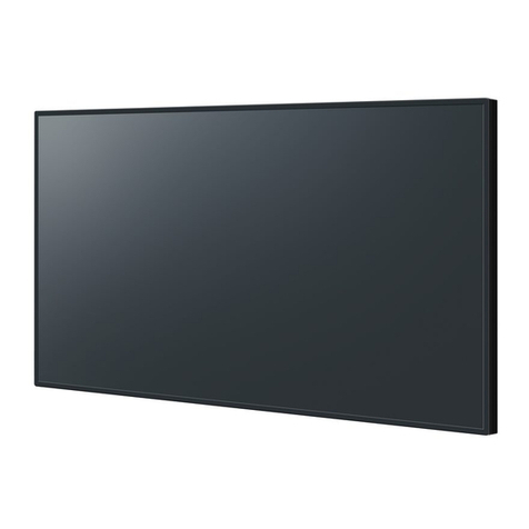
Panasonic TH-65EF1E Operating instructions

Panasonic
Panasonic Viera TH-50PF10UK User manual
Panasonic
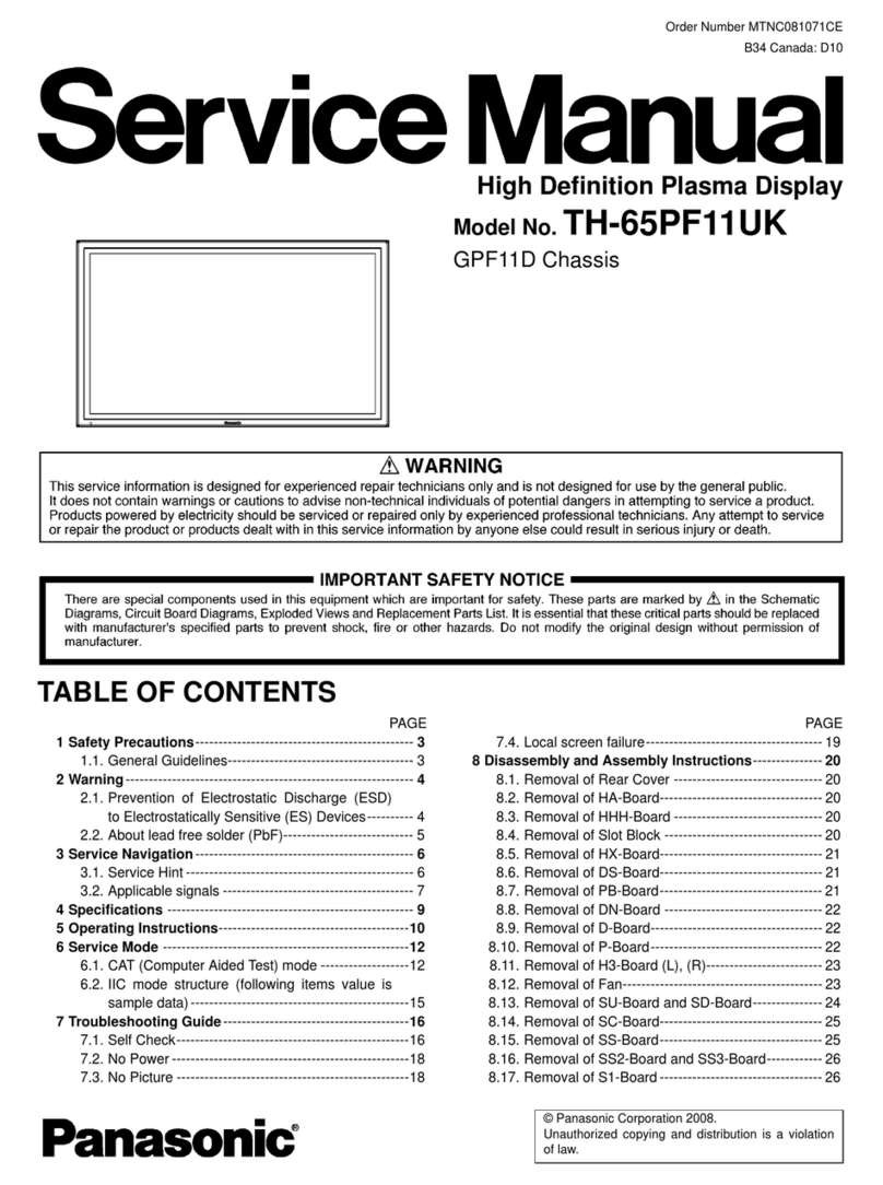
Panasonic TH-65PF11UK - 64.8" Plasma Panel User manual

Panasonic
Panasonic TH-58PF20U TENTATIVE User manual
Panasonic
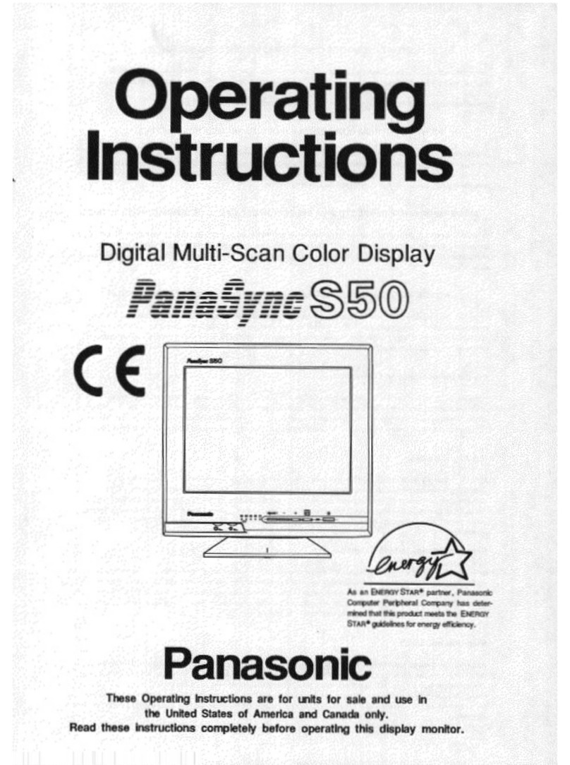
Panasonic PANASYNC S50 User manual

Panasonic
Panasonic TH-50PH30W User manual
Panasonic
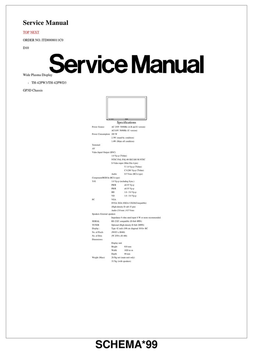
Panasonic Viera TH-42PW3 User manual


