manuals.online logo
Brands
  1. Home
  2. •
  3. Brands
  4. •
  5. Panasonic
  6. •
  7. Monitor
  8. •
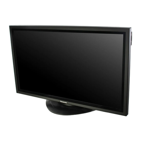
  9. Panasonic TH-50PHW6BX User manual

Panasonic TH-50PHW6BX User manual

Other manuals for TH-50PHW6BX

2

This manual suits for next models

3

Other Panasonic Monitor manuals

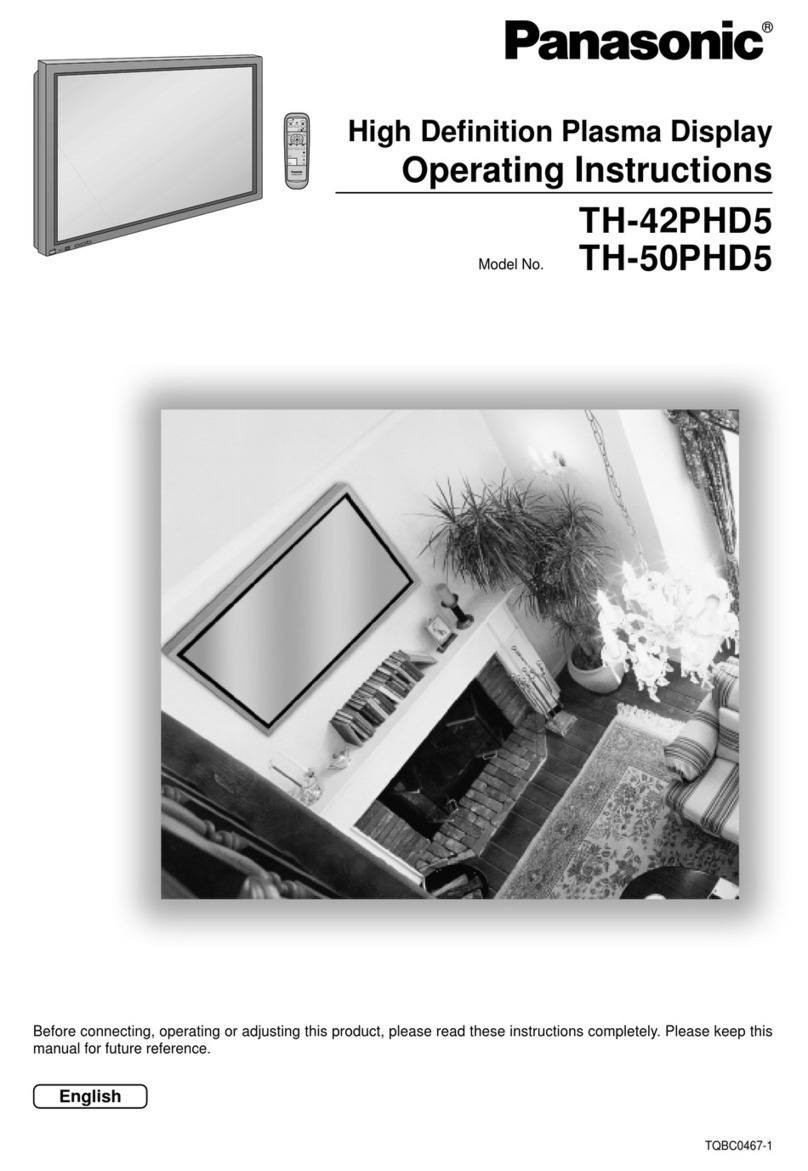
Panasonic TH-42PH30U User manual

Panasonic

Panasonic TH-42PH30U User manual

Panasonic TH-50PHW3 User manual

Panasonic

Panasonic TH-50PHW3 User manual

Panasonic TH-55VF1HU Owner's manual

Panasonic

Panasonic TH-55VF1HU Owner's manual

Panasonic TH 50PHD3 User manual

Panasonic

Panasonic TH 50PHD3 User manual

Panasonic WV-CM1020 User manual

Panasonic

Panasonic WV-CM1020 User manual

Panasonic TH-55LFV9U User manual

Panasonic

Panasonic TH-55LFV9U User manual

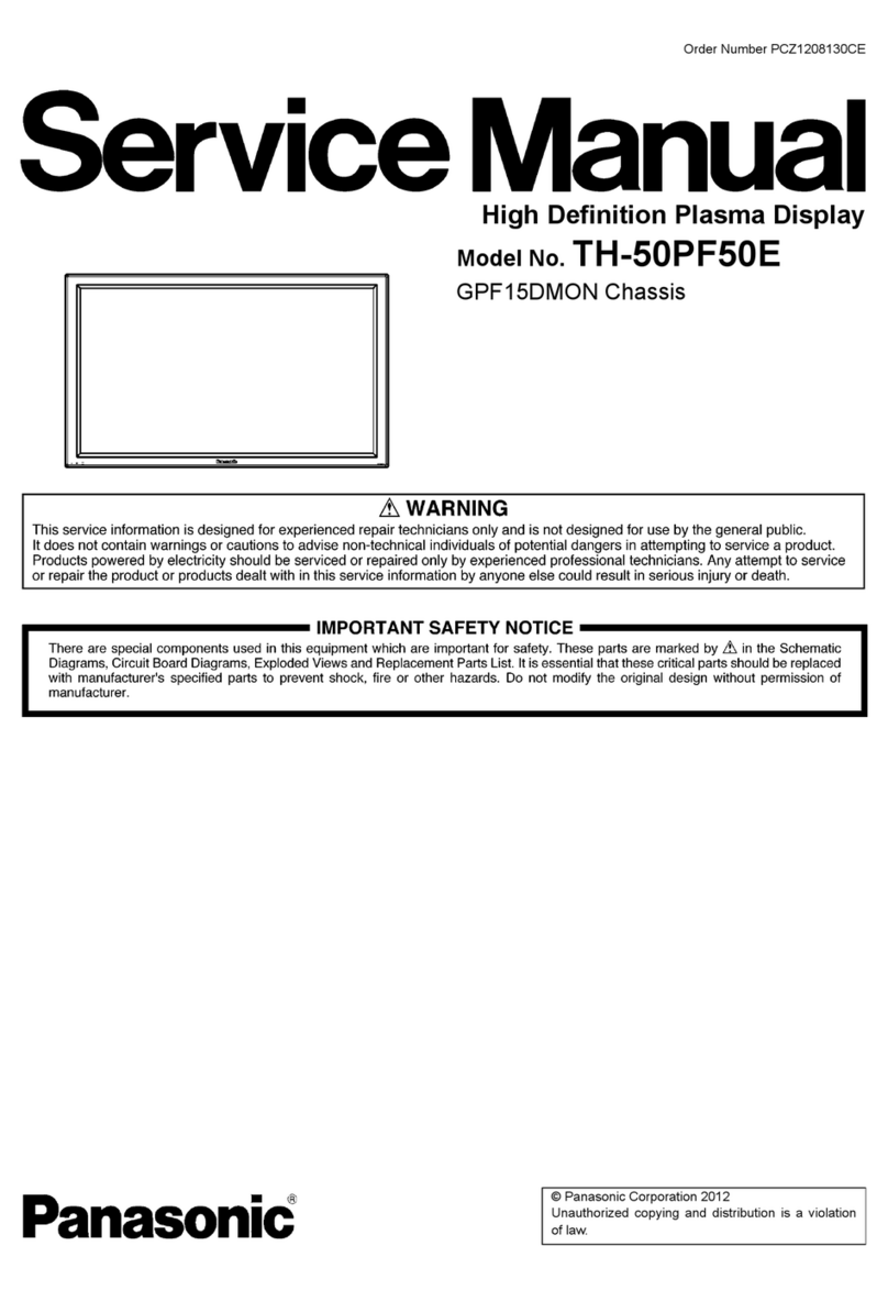
Panasonic TH-42PF50E User manual

Panasonic

Panasonic TH-42PF50E User manual

Panasonic SF2H Series User manual

Panasonic

Panasonic SF2H Series User manual

Panasonic DT1300MS - DISPLAY MONITOR User manual

Panasonic

Panasonic DT1300MS - DISPLAY MONITOR User manual

Panasonic BT-LH900 User manual

Panasonic

Panasonic BT-LH900 User manual

Panasonic TH-55LFV50U User manual

Panasonic

Panasonic TH-55LFV50U User manual

Panasonic AG-LC35HP User manual

Panasonic

Panasonic AG-LC35HP User manual

Panasonic TH-103PF9EK User manual

Panasonic

Panasonic TH-103PF9EK User manual

Panasonic TH-103PF10EK User manual

Panasonic

Panasonic TH-103PF10EK User manual

Panasonic Viera TH-42PWD4 User manual

Panasonic

Panasonic Viera TH-42PWD4 User manual

Panasonic TH-55LFV5W User manual

Panasonic

Panasonic TH-55LFV5W User manual

Panasonic TH-42LF25W User manual

Panasonic

Panasonic TH-42LF25W User manual

Panasonic VIERA TH-P55VT60A User manual

Panasonic

Panasonic VIERA TH-P55VT60A User manual

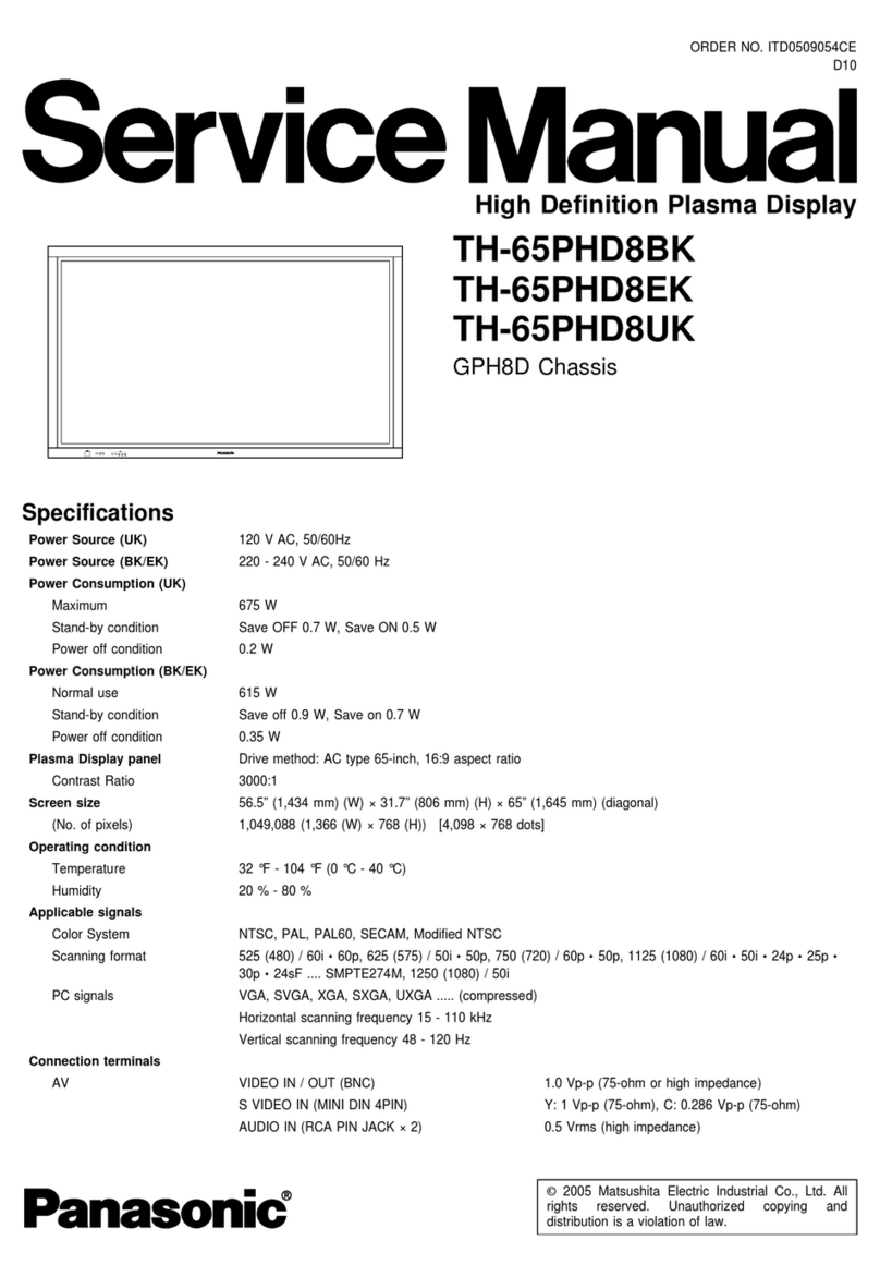
Panasonic TH-65PF12EK User manual

Panasonic

Panasonic TH-65PF12EK User manual

Panasonic CFVDW07M - COMPUTER WIRELESS DISPLAY Instruction sheet

Panasonic

Panasonic CFVDW07M - COMPUTER WIRELESS DISPLAY Instruction sheet

Panasonic TH-50PH30U User manual

Panasonic

Panasonic TH-50PH30U User manual

Panasonic TH-47LFT30W User manual

Panasonic

Panasonic TH-47LFT30W User manual

Panasonic TH-152UX1W User manual

Panasonic

Panasonic TH-152UX1W User manual

Panasonic TH32LRT12U - HD LCD DISPLAY User manual

Panasonic

Panasonic TH32LRT12U - HD LCD DISPLAY User manual

Popular Monitor manuals by other brands

Samsung ME32C user manual

Samsung

Samsung ME32C user manual

ViewSonic VA926-LED user guide

ViewSonic

ViewSonic VA926-LED user guide

Furuno Mu 120c Operator's manual

Furuno

Furuno Mu 120c Operator's manual

Asus VB171D - 17" LCD Monitor Service manual

Asus

Asus VB171D - 17" LCD Monitor Service manual

AOC 9GLR Technical specifications

AOC

AOC 9GLR Technical specifications

DMG RAFFAELLO manual

DMG

DMG RAFFAELLO manual

AOC LM720 - 17" Technical specifications

AOC

AOC LM720 - 17" Technical specifications

Sony Trinitron GDM-F500 Service manual

Sony

Sony Trinitron GDM-F500 Service manual

Memorex MT1701 user guide

Memorex

Memorex MT1701 user guide

ViewSonic VE510s-4 Service manual

ViewSonic

ViewSonic VE510s-4 Service manual

Farenheit T-1503CM instruction manual

Farenheit

Farenheit T-1503CM instruction manual

Ditel DINOS DN129/AT Quick installation guide

Ditel

Ditel DINOS DN129/AT Quick installation guide

Sony SDM-S51 Specifications

Sony

Sony SDM-S51 Specifications

Kenwood DMX1025BT quick start guide

Kenwood

Kenwood DMX1025BT quick start guide

Dell S2409WFP user guide

Dell

Dell S2409WFP user guide

EverFocus EN-7517E instruction manual

EverFocus

EverFocus EN-7517E instruction manual

Dell P3222QE user guide

Dell

Dell P3222QE user guide

LG 50PM1M -  - 50" Plasma Panel Service manual

LG

LG 50PM1M - - 50" Plasma Panel Service manual

manuals.online logo
manuals.online logoBrands
  • About & Mission
  • Contact us
  • Privacy Policy
  • Terms and Conditions

Copyright 2025 Manuals.Online. All Rights Reserved.

50phw6bx.html
Table Of Contents
COVER
1 Applicable signals
2 Safety Precautions
2.1 General Guidelines
2.1.1 Leakage Current Cold Check
2.1.2 Leakage Current Hot Check
(See Figure 1 .)
3 Prevention of Electro Static
Discharge (ESD) to Electrostatically
Sensitive (ES) Devices
4 About lead free solder (PbF)
5 PCB Structure sheet of GPH6D2
chassis
6 Service Hint
7 Location of Lead Wiring
8 Adjustment Procedure
8.1 Driver Set-up
8.1.1 Item / Preparation
8.1.2 Adjustments
8.2 Initialization Pulse Adjust
8.3 P.C.B. (Printed Circuit Board)
exchange
8.3.1 Caution
8.3.2 Quick adjustment after P.C.B.
exchange
8.4 Adjustment Volume Location
8.5 Test Point Location
9 Service mode
9.1 CAT (computer Aided Test)
mode
9.1.1 IIC mode
9.1.2 CD mode
9.1.3 SD mode
9.2 IIC mode structure (following
items value is sample data.)
10 Alignment
10.1 Pedestal setting (C)
10.2 Pedestal setting (B)
10.3 NTSC panel white balance
10.4 PAL / SECAM panel white
balance
10.5 PC / RGB panel white
balance
10.6 HD / 525i / 525p /
625I / 625P panel white balance
11 Trouble shooting guide
11.1 Self Check
11.2 No Power
11.2.1 Power LED Blinking timing
Service Manual
TOP NEXT
ORDER NO. ITD0309034C0
D10 Canada: B07
High Definition Plasma Display
● TH-50PHW6BX
TH-50PHW6EX
TH-50PHD6EX
TH-50PHD6BX
TH-50PHD6UY
GPH6D2 Chassis
Specifications
Power Source: AC120V 50/ 60Hz (UY version)
AC220-240V 50/ 60Hz
(Except UY version model)
Power Consumption: 445 W
Save off 1.6 W, Save on 0.9 W (stand-by condition)
(UY version)
Save off 1.9 W, Save on 1.1 W (stand-by condition)
(Except UY version model)
0.2 W (Power off condition)
(UY version model)
0.4 W (Power off condition)
(Except UY version model)
Plasma Display panel: Drive method AC type
16:9 aspect ratio
Contrast Ratio 3000:1
Screen size: 1,106 mm (W)× 622 mm (H)
1,269 mm (diagonal)
No. of pixels
1,049,088 (1,366 (W)× 768 (H))
[4,098× 768 dots]
Operating condition:
Temperature 34° F - 104° F (0° C - 40° C)
Humidity 20% - 80%
Horizontal scanning frequency 15 - 110kHz
Vertical scanning frequency 48 - 120Hz
Connection terminals:
AV
Video in 1.0 Vp-p (75-ohm)
file:///E|/TH-50PHW6BX_TH-50PHW6EX_TH-50PHD6EX_TH-50PHD6BX_TH-50PHD6UY/SVC/Kopia%20PVAccel.html (1 z 4) [2006-01-21 10:05:49]
50phw6bx.html
chart
11.2.2 Power LED no light
11.3 No Picture
11.4 Local screen failure
12 Option Setting
12.1 How to access and setting
12.2 Contents of Option Menu
13 Conductor Views
13.1 PF-Board
13.2 P-Board
13.3 HX-Board
13.4 HY-Board
13.5 J-Board
13.6 D-Board
13.7 C1-Board
13.8 C2-Board
13.9 C3-Board
13.10 C4-Board
13.11 C5-Board
13.12 C6-Board
13.13 SC-Board
13.14 SU-Board
13.15 SD-Board
13.16 SS, SS2 and SS3-Board
13.17 Z-Board
13.18 V1, S1 and H3-Board
14 Schematic Diagrams
14.1 Schematic Diagram Notes
14.2 Main Block Diagram
14.3 P and PF-Board Block Diagram
14.4 PF-Board Schematic Diagram
14.5 P-Board (1 of 6) Schematic
Diagram
14.6 P-Board (2 of 6) Schematic
Diagram
14.7 P-Board (3 of 6) Schematic
Diagram
14.8 P-Board (4 of 6) Schematic
Diagram
14.9 P-Board (5 of 6) Schematic
Diagram
14.10 P-Board (6 of 6) Schematic
Diagram
14.11 HX-Board Block Diagram
14.12 HX-Board Schematic Diagram
14.13 HY-Board Block Diagram
14.14 HY-Board (1 of 3) Schematic
Diagram
14.15 HY-Board (2 of 3) Schematic
Diagram
S-VIDEO IN
(MINI DIN 4PIN)
Y: 1 Vp-p (75-ohm), C: 0.286 Vp-p (75-ohm)
AUDIO IN
(RCA PIN JACK× 2)
0.5 Vrms (high impedance)
COMPONENT/ RGB
Y/ G 1.0 Vp-p/ composite (75-ohm)
0.7 Vp-p/ non-composite (75-ohm)
P B/ B 0.7 Vp-p (75-ohm)
P R/ R 0.7 Vp-p (75-ohm)
HD 1.0 - 5.0 Vp-p (high impedance)
VD 1.0 - 5.0 Vp-p (high impedance)
AUDIO IN
(RCA PIN JACK× 2)
0.5 Vrms (high impedance)
PC
(HIGH-DENSITY
D-SUB15PIN)
R,G,B/ 0.7 Vp-p (75-ohm)
HD, VD/ 1.0 - 5.0 Vp-p (high impedance)
AUDIO IN (M3 JACK) 0.5Vrms (high impedance)
SERIAL
EXTERNAL CONTROL
TERMINAL (D-SUB9PIN)
RS-232C COMPATIBLE
SPEAKERS (External speakers) (6Ω ) 16W [8W+ 8W] (10% THD)
Dimensions (W× H× D): 1,210 mm× 724 mm 95 mm
Weight (Mass) approx. 43.5 kg net (main unit only)
approx. 48.1 kg net (with speakers)
© 2003 Matsushita Electric Industrial Co., Ltd. All rights reserved. Unauthorized copying and distribution is a violation of law.
TOP NEXT
file:///E|/TH-50PHW6BX_TH-50PHW6EX_TH-50PHD6EX_TH-50PHD6BX_TH-50PHD6UY/SVC/Kopia%20PVAccel.html (2 z 4) [2006-01-21 10:05:49]
file:///E|/TH-50PHW6BX_TH-50PHW6EX_TH-50PHD6EX_TH-50PHD6BX_TH-50PHD6UY/SVC/50phw6bx.html
Table Of Contents
COVER
1 Applicable signals
2 Safety Precautions
2.1 General Guidelines
2.1.1 Leakage Current Cold Check
2.1.2 Leakage Current Hot Check (See Figure 1 .)
3 Prevention of Electro Static Discharge (ESD) to Electrostatically Sensitive (ES) Devices
4 About lead free solder (PbF)
5 PCB Structure sheet of GPH6D2 chassis
6 Service Hint
7 Location of Lead Wiring
8 Adjustment Procedure
8.1 Driver Set-up
8.1.1 Item / Preparation
8.1.2 Adjustments
8.2 Initialization Pulse Adjust
8.3 P.C.B. (Printed Circuit Board) exchange
8.3.1 Caution
8.3.2 Quick adjustment after P.C.B. exchange
file:///E|/TH-50PHW6BX_TH-50PHW6EX_TH-50PHD6EX_TH-50PHD6BX_TH-50PHD6UY/SVC/50phw6bx.html (1 z 7) [2006-01-21 10:03:53]
file:///E|/TH-50PHW6BX_TH-50PHW6EX_TH-50PHD6EX_TH-50PHD6BX_TH-50PHD6UY/SVC/50phw6bx.html
8.4 Adjustment Volume Location
8.5 Test Point Location
9 Service mode
9.1 CAT (computer Aided Test) mode
9.1.1 IIC mode
9.1.2 CD mode
9.1.3 SD mode
9.2 IIC mode structure (following items value is sample data.)
10 Alignment
10.1 Pedestal setting (C)
10.2 Pedestal setting (B)
10.3 NTSC panel white balance
10.4 PAL / SECAM panel white balance
10.5 PC / RGB panel white balance
10.6 HD / 525i / 525p / 625I / 625P panel white balance
11 Trouble shooting guide
11.1 Self Check
11.2 No Power
11.2.1 Power LED Blinking timing chart
11.2.2 Power LED no light
11.3 No Picture
file:///E|/TH-50PHW6BX_TH-50PHW6EX_TH-50PHD6EX_TH-50PHD6BX_TH-50PHD6UY/SVC/50phw6bx.html (2 z 7) [2006-01-21 10:03:53]
file:///E|/TH-50PHW6BX_TH-50PHW6EX_TH-50PHD6EX_TH-50PHD6BX_TH-50PHD6UY/SVC/50phw6bx.html
11.4 Local screen failure
12 Option Setting
12.1 How to access and setting
12.2 Contents of Option Menu
13 Conductor Views
13.1 PF-Board
13.2 P-Board
13.3 HX-Board
13.4 HY-Board
13.5 J-Board
13.6 D-Board
13.7 C1-Board
13.8 C2-Board
13.9 C3-Board
13.10 C4-Board
13.11 C5-Board
13.12 C6-Board
13.13 SC-Board
13.14 SU-Board
13.15 SD-Board
file:///E|/TH-50PHW6BX_TH-50PHW6EX_TH-50PHD6EX_TH-50PHD6BX_TH-50PHD6UY/SVC/50phw6bx.html (3 z 7) [2006-01-21 10:03:53]
file:///E|/TH-50PHW6BX_TH-50PHW6EX_TH-50PHD6EX_TH-50PHD6BX_TH-50PHD6UY/SVC/50phw6bx.html
13.16 SS, SS2 and SS3-Board
13.17 Z-Board
13.18 V1, S1 and H3-Board
14 Schematic Diagrams
14.1 Schematic Diagram Notes
14.2 Main Block Diagram
14.3 P and PF-Board Block Diagram
14.4 PF-Board Schematic Diagram
14.5 P-Board (1 of 6) Schematic Diagram
14.6 P-Board (2 of 6) Schematic Diagram
14.7 P-Board (3 of 6) Schematic Diagram
14.8 P-Board (4 of 6) Schematic Diagram
14.9 P-Board (5 of 6) Schematic Diagram
14.10 P-Board (6 of 6) Schematic Diagram
14.11 HX-Board Block Diagram
14.12 HX-Board Schematic Diagram
14.13 HY-Board Block Diagram
14.14 HY-Board (1 of 3) Schematic Diagram
14.15 HY-Board (2 of 3) Schematic Diagram
14.16 HY-Board (3 of 3) Schematic Diagram
14.17 J-Board Block Diagram
file:///E|/TH-50PHW6BX_TH-50PHW6EX_TH-50PHD6EX_TH-50PHD6BX_TH-50PHD6UY/SVC/50phw6bx.html (4 z 7) [2006-01-21 10:03:53]
file:///E|/TH-50PHW6BX_TH-50PHW6EX_TH-50PHD6EX_TH-50PHD6BX_TH-50PHD6UY/SVC/50phw6bx.html
14.18 J-Board (1 of 4) Schematic Diagram
14.19 J-Board (2 of 4) Schematic Diagram
14.20 J-Board (3 of 4) Schematic Diagram
14.21 J-Board (4 of 4) Schematic Diagram
14.22 D-Board (1 of 2) Block Diagram
14.23 D-Board (2 of 2) Block Diagram
14.24 D-Board (1 of 15) Schematic Diagram
14.25 D-Board (2 of 15) Schematic Diagram
14.26 D-Board (3 of 15) Schematic Diagram
14.27 D-Board (4 of 15) Schematic Diagram
14.28 D-Board (5 of 15) Schematic Diagram
14.29 D-Board (6 of 15) Schematic Diagram
14.30 D-Board (7 of 15) Schematic Diagram
14.31 D-Board (8 of 15) Schematic Diagram
14.32 D-Board (9 of 15) Schematic Diagram
14.33 D-Board (10 of 15) Schematic Diagram
14.34 D-Board (11 of 15) Schematic Diagram
14.35 D-Board (12 of 15) Schematic Diagram
14.36 D-Board (13 of 15) Schematic Diagram
14.37 D-Board (14 of 15) Schematic Diagram
file:///E|/TH-50PHW6BX_TH-50PHW6EX_TH-50PHD6EX_TH-50PHD6BX_TH-50PHD6UY/SVC/50phw6bx.html (5 z 7) [2006-01-21 10:03:53]
file:///E|/TH-50PHW6BX_TH-50PHW6EX_TH-50PHD6EX_TH-50PHD6BX_TH-50PHD6UY/SVC/50phw6bx.html
14.38 D-Board (15 of 15) Schematic Diagram
14.39 C1, C2, C3, C4, C5, C6 and V1-Board Block Diagram (1 of 2)
14.40 C1, C2, C3, C4, C5, C6 and V1-Board Block Diagram (2 of 2)
14.41 C1-Board (1 of 2) Schematic Diagram
14.42 C1-Board (2 of 2) Schematic Diagram
14.43 C2-Board Schematic Diagram
14.44 C3-Board (1 of 2) Schematic Diagram
14.45 C3-Board (2 of 2) Schematic Diagram
14.46 C4-Board (1 of 2) and V1-Board Schematic Diagram
14.47 C4-Board (2 of 2) Schematic Diagram
14.48 C5-Board Schematic Diagram
14.49 C6-Board (1 of 2) Schematic Diagram
14.50 C6-Board (2 of 2) Schematic Diagram
14.51 SC-Board Block Diagram
14.52 SC-Board (1 of 3) Schematic Diagram
14.53 SC-Board (2 of 3) Schematic Diagram
14.54 SC-Board (3 of 3) Schematic Diagram
14.55 SU-Board Block Diagram
14.56 SU-Board (1 of 2) Schematic Diagram
14.57 SU-Board (2 of 2) Schematic Diagram
14.58 SD-Board Block Diagram
file:///E|/TH-50PHW6BX_TH-50PHW6EX_TH-50PHD6EX_TH-50PHD6BX_TH-50PHD6UY/SVC/50phw6bx.html (6 z 7) [2006-01-21 10:03:53]
file:///E|/TH-50PHW6BX_TH-50PHW6EX_TH-50PHD6EX_TH-50PHD6BX_TH-50PHD6UY/SVC/50phw6bx.html
14.59 SD-Board (1 of 2) Schematic Diagram
14.60 SD-Board (2 of 2) Schematic Diagram
14.61 SS, S1, SS2 and SS3-Board Block Diagram
14.62 SS-Board (1 of 2) and S1-Board Schematic Diagram
14.63 SS-Board (2 of 2), SS2 and SS3-Board Schematic Diagram
14.64 Z-Board and H3-Board Block Diagram
14.65 Z-Board (1 of 2) and H3-Board Schematic Diagram
14.66 Z-Board (2 of 2) Schematic Diagram
15 Parts Location
16 Mechanical Replacement Parts List
17 Replacement Parts List
17.1 Relpacement Parts List Notes
17.2 Electrical Replacement List
18 Schematic Diagram for printing with A4 size
19 Cover for printing with A4
file:///E|/TH-50PHW6BX_TH-50PHW6EX_TH-50PHD6EX_TH-50PHD6BX_TH-50PHD6UY/SVC/50phw6bx.html (7 z 7) [2006-01-21 10:03:53]
PV
Navigator
Table Of Contents
COVER
1 Applicable signals
2 Safety Precautions
2.1 General Guidelines
2.1.1 Leakage Current Cold Check
2.1.2 Leakage Current Hot Check (See Figure 1 .)
3 Prevention of Electro Static Discharge (ESD) to Electrostatically Sensitive (ES) Devices
4 About lead free solder (PbF)
5 PCB Structure sheet of GPH6D2 chassis
6 Service Hint
7 Location of Lead Wiring
8 Adjustment Procedure
8.1 Driver Set-up
8.1.1 Item / Preparation
8.1.2 Adjustments
8.2 Initialization Pulse Adjust
8.3 P.C.B. (Printed Circuit Board) exchange
8.3.1 Caution
8.3.2 Quick adjustment after P.C.B. exchange
8.4 Adjustment Volume Location
8.5 Test Point Location
9 Service mode
9.1 CAT (computer Aided Test) mode
9.1.1 IIC mode
9.1.2 CD mode
9.1.3 SD mode
9.2 IIC mode structure (following items value is sample data.)
10 Alignment
10.1 Pedestal setting (C)
10.2 Pedestal setting (B)
10.3 NTSC panel white balance
10.4 PAL / SECAM panel white balance
10.5 PC / RGB panel white balance
file:///E|/TH-50PHW6BX_TH-50PHW6EX_TH-50PHD6EX_TH-50PHD6BX_TH-50PHD6UY/SVC/navigator.html (1 z 4) [2006-01-21 10:04:10]