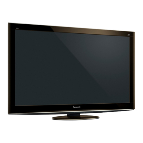
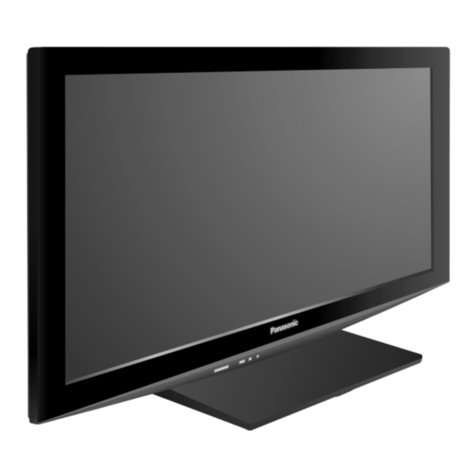
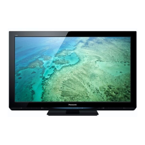
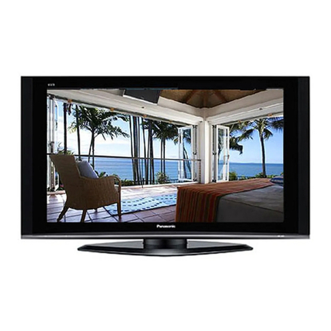
TH-50PV600AZ / TH-50PV600H / TH-50PV600M / TH-50PV600MT
A WARNING
This service inform tion is designed for experienced rep ir technici ns only nd is not designed for use by the gener l public.
It does not cont in w rnings or c utions to dvise non-technic l individu ls of potenti l d ngers in ttempting to service product.
Products powered by electricity should be serviced or rep ired only by experienced profession l technici ns. Any ttempt to service
or rep ir the product or products de lt with in this service inform tion by nyone else could result in serious injury or de th.
ONTENTS Page
1 Applicable signals..............................................................................5
2 Safety Precautions.............................................................................6
2.1. General Guidelines
..................................................................6
2.2. Touch- urrent heck.............................................................. 6
3 Prevention of Electro Static Discharge (ESD) to
Electrostatically Sensitive (ES) Devices.......................................7
4 About lead free solder (PbF)............................................................8
5 Service Hint..........................................................................................9
6 Plasma panel replacement method..............................................10
6.1. Remove the Back cover....................................................10
6.2. Remove the fan................................................................. 10
6.3. Remove the Speaker box ass’y (left)..............................10
6.4. Remove the Speaker box ass’y (right)
...........................
10
6.5. Remove the rear terminal cover
......................................
10
6.6. Remove the P-Board
......................................................... 11
6.7. Remove the PA-Board......................................................12
6.8. Remove the tuner unit......................................................12
6.9. Remove the DG-Board..................................................... 12
6.10. Remove the TA-Board........................................................12
6.11. Remove the H-Board...........................................................13
6.12. Remove the H -Board........................................................13
6.13. Remove the D-Board...........................................................13
6.14. Remove the SU-Board........................................................13
6.15. Remove the SD-Board........................................................14
6.16. Remove the S -Board........................................................14
6.17. Remove the SS2-Board......................................................14
6.18. Remove the SS3-Board......................................................14
6.19. Remove the SS-Board........................................................15
6.20. Remove the 1-Board........................................................ 15
6.21. Remove the 2-Board........................................................ 15
6.22. Remove the 3-Board........................................................ 15
6.23. Remove the stand brackets...............................................16
6.24. Remove the 4-Board........................................................ 16
6.25. Remove the 5-Board........................................................ 16
6.26. Remove the 6-Board........................................................ 16
6.27. Remove the front bracket...................................................17
6.28. Remove the G-Board, GK-Board and GS-Board
............
17
6.29. Remove the S-Board...........................................................17
6.30. Remove the GS-Board and SD-Module
...........................
17
6.31. Remove the Plasma panel section from the Front frame
(glass)...................................................................................... 18
6.32. Remove the squawker speaker
.........................................
19
6.33. Remove the K-Board...........................................................19
6.34. Replace the plasma panel (finished)
................................
20
7 Location of Lead Wiring..................................................................21
7.1. Lead of Wiring (1).................................................................21
3
Page
7.2. Lead of Wiring (2)
.................................................................. 22
7.3. Lead of Wiring (3)..................................................................23
7.4. Lead of Wiring (4)..................................................................24
7.5. Lead of Wiring (5)..................................................................25
8 Self-check Function......................................................................... 26
8.1. Power LED Blinking timing chart..........................................27
8.2. No Power.................................................................................28
8.3. No Picture................................................................................29
8.4. Local screen failure................................................................30
9 Service Mode Function....................................................................31
9.1. Howto enter SERVI E 1 .....................................................31
9.2. How to enter SERVI E 2 .....................................................31
9.3. Option Description..................................................................33
10 Adjustment Procedure.....................................................................35
10.1. Driver Set-up...........................................................................35
10.2. Initialization Pulse Adjust.......................................................36
10.3. P. .B. (Printed ircuit Board) exchange.............................36
10.4. Adjustment Volume Location................................................37
10.5. Test Point Location................................................................37
11 Adjustment......................................................................................... 38
11.1. PAL panel white balance adjustment..................................38
11.2. HD white balance adjustment...............................................39
11.3. Sub bright adjustment............................................................40
11.4. ABL adjustment.......................................................................41
11.5. Sub- ontrast adjustment.......................................................42
11.6. Multi-window adjustment.......................................................43
12 Hotel mode.........................................................................................44
13 onductor Views..............................................................................45
13.1. P-Board....................................................................................45
13.2. PA-Board.................................................................................48
13.3. H, H and TA-Board..............................................................50
13.4. G-Board................................................................................... 52
13.5. GK, K and S-Board................................................................53
13.6. DG-Board.................................................................................54
13.7. D-Board....................................................................................56
13.8. 1-Board................................................................................. 58
13.9. 2-Board................................................................................. 59
13.10. 3-Board................................................................................. 60
13.11. 4-Board..................................................................................61
13.12. 5-Board................................................................................. 62
13.13. 6-Board................................................................................. 63
13.14. S -Board.................................................................................64
13.15. SU-Board.................................................................................67
13.16. SD-Board.................................................................................68
13.17. SS-Board.................................................................................69
13.18. SS-Board..................................................................................71
