manuals.online logo
Brands
  1. Home
  2. •
  3. Brands
  4. •
  5. Panasonic
  6. •
  7. Projector
  8. •
  9. Panasonic PT-302 User manual

Panasonic PT-302 User manual

ORDER
NO.
VED86100027C3
ervice
Manual
Colour
Video
Projector
PT-302
chassis
No.
Q5
The
service
technician
is
required
to
read
and
follow
the
‘‘Safety
Precautions’
and
’’Important
Safety
Notice”
in
this
service
manual.
Specifications
Power
Source:
AC
220V
~
240V,
50/60
Hz
4318
mm
(170
inch)
Picture
size:
Power
Consumption:
179W
(average)
5102
mm
(200
7/8
inch)
Projection
T
ube:
7
inches
(179
mm)
specially
developed
5080
mm
(200
inch)
Picture
size:
High-Brightness
liquid
cooled
5963
mm
(234
3/4
inch)
CRTs
(R,
G,
B).
6350
mm
(250
inch)
Picture
size:
Lenses:
Double
Focus,
Three
F
1.0
145
7400
mm
(291
11/32
inch)
Lenses
(HYBRID)
7620
mm
(300
inch)
Picture
size:
Resolution:
Video......
650
TV
Lines
(typical)
8835
mm
(345
27/32
inch)
RGB........
1000
TV
Lines
(typical)
Light
Flux:
500
lumens
(typical)
at
white
peak
Video
Input
Level:
140.3Vp-p
75Q
Operating
Ambient
Line
in/out
Level:
1+0,3Vp-p
75Q
or
high
impedance
Temperature:
32°F
~
104°F
(0°C
~
+40°C)
RGB
Input
Level
R:
0.74+0.3Vp-p
752
Operating
Ambient
G:
0.7+0.3Vp-p
75Q
Humidity:
20%
~
80%
(GSYNC:
140.3Vp-p
75Q)
Supplied
Accessories:
AC
Cord
(3
types)
B:
0.7+0.3Vp-p
75
Mounting
kit
(1
set)
H/HV:
0.3
~
6V,
high
impedance
Dimensions:
Height:
290
mm
(11
13/32
inch)
V:
0.3
~
6V,
high
impedance
Width:
576mm
(22
11/16
inch}
Screen
Size:
3810
~
7620
mm
(150
~
300
inch)
Depth:
606
mm
(23
29/32
inch)
Throw
Distance:
3810
mm
(150
inch)
Picture
size:
Weight:
77
\|bs.
(35
kg)
4528
mm
(178
1/4
inch)
;
Specifications
are
subject
to
change
without
notice.
Weight
and
dimensions
shown
are
approximate.
a
rs Fy
5
Panasonic
Matsushita
Elecite
Weds
Co.
PT-302
CONTENTS
FEATURES
oc.
o's Sys ase
8
ad
Reece
che
erarae
Beddacs
ar
ahaa
Ay.
eee
a
eee
RO
oes
ee
A
2
SAFETY
PRECAUTIONS
225.25
iecce
Sie
5
ata
ela
alee
le
esti
ee
tee
as
Wwe
Gee
a
Ste
9
She
3
LOCATION
OF
CONTROLS,
OPERATIONS
AND
CONNECTION
OPTIONAL
EQUIPMENT...........
0.00
cue
ue
c
ences
4~8
DISASSEMBLY
INSTRUCTIONS
...........
00.
ccc
cere
eee
ne
eres
9,10
MAIN
PARTS
LOCATION
CHART
..........
0...
cc
cece
cece
ee
tee
ere
eens
11
CAUTIONS
FOR
SERVICING
.........
0...
ccc
ee
ee
eee
eens
12,13
FIELD
ADJUSTMENTS.
.....
2...
..
eee
e
ee
eee
eee
eee
eee
eee
ane
14
~20
INSTALLATION/ADJUSTMENT
PROCEDURE
..............0
000
ec
ucuae
21
~
32
LOCATION
OF
TEST
POINT
AND
CONTROLS
............
00
veer
e
eee eee
33
~
35
BLOCK
DIAGRAM).
6.5.4.0
6-06
eee
g
ow
be
Ses
COS
Se
EO
Hews
Gee
Rae
36
~
38
INTERCONNECTION...
0...
0...
cc
cee
eee
eee
ee
ee
eee
eee
ee
eee
39,
40
TERMINAL
GUIDE
OF
IC’S,
TRANSISTOR
AND
DIODES.
..............0
0000
ae
41
CIRCUIT:
BOARD
i
oie:
oa
hia
ish
ae.
hb
Gee
ie
ee
SPR
ew
le
Ge
Oe
bala
wee
42
~
54
SCHEMATIC
DIAGRAM
.........
0.0.
ecw
ee
ee
ee
eee
eee
anaes
55
~
74
F/K/P/Q/V/X-BOARD
Sections.
.........
0.00
cece
eee
ee
eee
eee
ee
ees
57,
58
M-BOARD
Section
.......
0.0...
ce
eee
eee
ewe
eee
ee
eee
eens
59,
60
B/S/LR/LG/LB-BOARD
Sections...
..........
00
cc
eee
uceceucuveees
65
~
68
C/J/TR1/TR2-BOARD
Sections...
2.2...
0.0...
cece
ee
eee
ee
69
~
71
A/G/R/T-BOARD
Sections...
0.0...
0...
cece
ee
ee
et
eee
eee
72
~74
EXPLODED:
VIEWS
en.
5:
ees
cece
ese
el
a
a
ote
eae
eae
eee.
AS.
rete
bl
ce
75
~
80
TROUBLESHOOTING.
....
0.0...
cece
ccc
eee
eee
te
eee
81,
82
REPLACEMENT
PARTS
LIST...
0...
..
eee
ee
ee
eee
eee
ees
83
~
110
FEATURES
1
Superb
bright
picture:
High
luminance
output:
5
Improved
raster
quality:
500
lumens
(typical)
at
white
peak
High
voltage
regulation
characteristic:
0.3
MQ
2
Superb
resolution:
1000
Lines
(RGB)
(typical)
6
eee
installation
and
front/rear
projection
easily
selectable.
650
Lines
(Video)
(typical)
RGB
character
reproduction:
e
Ceiling
mount/front
projection
e
Ceiling
mount/rear
projection
equivalent
to
2000
characters
e
Floor
placement/front
projection
(80
x
25)
e
Ceiling
mount
rear
projection
with
mirror
3
Compact
size
and
light
weight
(35
kg,
77
Ibs),
for
easy
¢
Floor
placement
rear
projection
with
mirror
7
Wide-range
computer
compatibility
placement/installation.
aor
. : . :
8
Four
broadcast
system
capabilit
4
Compatibility
with
various
signal
input
sources:
sys
Spe
arty
PAL,
SECAM,
NTSC
and
M-NTSC
4.43
VTR/VCR
Video
Disk
Video
Camera
RGB
Computer
TV
Tuner
SAFETY
PRECAUTIONS
GENERAL
GUIDELINES
1.
It
is
advisable
to
use
an
isolation
transformer
in
the
AC
line
supply
before
servicing
this
model.
2.
When
servicing
observe
the
original
lead
dress,
especially
in
the
high
voltage
circuit.
In
case
of
a
short
circuit,
replace
every
part
which
has
overheated.
3.
After
servicing
observe
that
all
protective
devices
such
as
insulation
barriers,
fish
paper,
shields,
isolation
networks
and
fuses
are
properly
installed.
4.
Before
turning
the
receiver
on,
the
resistance
between
the
B+
line
and
chassis
ground
should
be
checked.
Connect
the
©
side
of
an
ohmmeter
to
the
B+
line
and
the
@
side
to
chassis
ground.
Each
line
should
have
more
resistance
than
specified,
as
follows:
B+
(B—)
Line
Minimum
Resistance
206V
10kQ
116V
3kQ.
27V
30022
17V
2002
12V
10022
10V
3Q
*
-17V
150Q
*
—
Side
to
ground
5.
If
the
set
is
not
intended
to
be
used
for
a
long
time,
the
power
cord
should
be
unplugged
from
the
AC
line
outlet.
6.
Potentials,
as
high
as
32.5
kV
are
present
when
this
set
is
in
operation.
Removal
of
the
covers
involves
the
danger
of
a
shock
hazard
from
the
set’s
power
supply.
Servicing
should
not
be
attempted
by
anyone
who
is
not
thoroughly
familiar
with
the
precautions
necessary
when
working
on
high-voltage
equipment.
Always
discharge
the
anode
of
the
projection
tube
to
the
set
chassis
before
handling
the
tube.
7.
After
servicing,
make
the
following
leakage
current
checks
to
prevent
a
shock
hazard.
LEAKAGE
CURRENT
COLD
CHECK
1.
Unplug
the
AC
cord
and
connect
a
jumper
between
the
two
plug
prongs.
2.
Turn
on
the
set.
3.
Measure
the
resistance
value
with
an
ohmmeter
between
the
jumpered
AC
plug
and
each
exposed
metallic
part
such
as
screwheads,
input
terminals,
control
shafts,
etc.
When
the
exposed
metallic
part
has
a
return
path
to
the
chassis,
the
reading
should
be
between
490
k{2
and
9
M&2.
When
the
exposed
metal
does
not
have
a
return
path
to
the
chassis,
the
reading
must
be
infinite.
—_
PT-302
LEAKAGE
CURRENT
HOT
CHECK
(See
Fig.
1)
I
Plug
the
AC
cord
directly
into
the
AC
outlet.
Do
not
use
an
isolation
transformer
for
this
check.
.
Connect
a
2
kQ,
10W
resistor,
in
series
with
an
exposed
metallic
part
on
the
receiver
and
an
earth
such
as
a
water
pipe.
.
Use
an
AC
voltmeter,
with
1000
ohms/volt
or
more
sensitivity,
to
measure
the
potential
across
the
resistor.
.
Check
each
exposed’
metallic
part,
and
measure
the
voltage
at
each
point.
.
Reverse
the
AC
plug
in
the
AC
outlet
and
repeat
each
of
the
above
measurements.
.
The
potential
at
any
point
should
not
exceed
1.4
volts
RMS.
_
In
case
a
measurement
is
outside
of
the
limits
specified,
there
is
a
possibility
of
a
shock
hazard,
and
the
receiver
should
be
repaired
and
rechecked
before
it is
returned
to
the
customer.
HOT-
CHECK
CIRCUIT
AC
VOLTMETER
(High
Impedance)
TO
WATER
PIPE
INSTRUMENT
’S
2kn,
LOW
J
(EARTH)
EXPOSED
METALLIC
PARTS
Fig.
1
X-RADIATION
WARNING:
|
The
potential
source
of
X-Radiation
in
the
color
Projection
System
is
the
High
Voltage
section
and
the
projection
tubes.
NOTE:
it
is
important
to
use
an
accurate,
peliodically,
calibrated
high
voltage
meter.
1.
Turn
the
Brightness
control
fully
counterclockwise.
.
Measure
the
High
Voltage.
The
high
voltage
meter
should
indicate
32
kV
+
0.5
kV.
If
the
upper
meter
indication
is
out
of
tolerance,
immediate
sevice
and
correction
is
required
to
prevent
the
possbility
of
premature
component
failure.
(Refer
to
hich
voltage
adjustment
in
the
manual.)
.
TO
prevent
an
X-Radiation
possibility,
it
ig
esen
tial
to
use
the
specified
projection
tube
only.
.
To
prevent
exposure
to
X-Radiation,
the
groy
ection
tube
shield
must
be
kept
in
place
with
power
ap
lied
to
the
set.
WARNING:
When
using
a
projection
tube
tet
jig
for
service,
ensure
that
jig
is
capable
otha
Nndling
32.5
kV
without
causing
X-Radiati«n.
PT-302
LOCATION
OF
CONTROLS,
OPERATION
AND
CONNECTING
OPTIONAL
EQUIPMENT
LOCATION
OF
CONTROLS
AC
IN
MAIN
POWER
SWITCH
IMPEDANCE
SELECTOR
SWITCH
LINE
IN/OUT
TERMINAL
VIDEO
INPUT
TERMINAL
G/EXT
SYNC
SELECTOR
SWITCH
V
INPUT
TERMINAL
H/HV
INPUT
TERMINAL
B
INPUT
TERMINAL
G/G
SYNC
INPUT
TERMINAL
R
INPUT
TERMINAL
BLUE
SELECTOR
@prower
SWITCH
SWITCH
TV
SYSTEM
SELECTOR
SWITCH
COLO
R
CONTRAST
SHARPNESS
OPERATION
TO
Operate
the
projector
switches
@
and
@
must
be
turned
ON,
and
switch
@
must
be
set
to
the
proper
input
signal
type.
Note:
When
the
separately
supplied
remote
controller
(ET-12R)
is
connected
to
the
video
projector,
switches
@
through
@
and
@
through
@
are
inoperable.
Please
use
the
remote
controiller
for
these
functions.
=
AS
Switch.
PURPOSE
MAIN
POWER
SWITCH
OFF
BL
=
ON
Switches
main
power
supply
ON/OFF.
MAIN
POWER
Power
ON/OFF
switch.
POWER
SWITCH
REMOTE
BH
=
ON
This
switch
is
set
to
the
OFF
position,
when
the
remote
control
is in
use.
RGB
LINE
VIDEO
VIDEO---Push
this
button
to
view
signals
input
via
the
VIDEO
input
terminal.
LINE
---Push
this
button
to
view
signals
input
via
the
LINE
input
terminal.
RGB_---Push
this
button
to
view
signals
input
via
the
RGB
INPUT
SELECTOR
input
terminal.
INPUT
SELECTOR
SWITCHES
This
switch
is
operable
only
when
RGB
signals
are
being
re-
NORMAL
.
a
ceived.
Use
this
switch
when
the
blue
portion
of
the
picture
is
weak.
FINE
BLUE
+
NI)
NORMAL
---Normal
blue.
BLUE
MONO-
FINE
BLUE
-:--A
finer
,
easier-on-the-eye,
blue.
BLUE
MONO:-:--White
picture
on
a
blue
back
ground.
Note:
When
Linear
or
TTL
RGB
signals
are
input
at
inappro-
BLUE
SELECTOR
priate
levels,
the
FINE
BLUE
and
BLUE
MONO
modes
might
not
operate
properly.
BLUE
SELECTOR
SWITCH
SECAM
,
This
switch
is
normally
set
at
AUTO.
PAL.
i
i
ity
i
TV
SYSTEM
igre:
eiedel
if
the
isk
eae
bad
.
the
use
of
dubbed
SELECTOR
SWITCH
Nee:
pes,
etc.,
reception
may
not
be
satis
ac
ory.
AUTO
*
In
that
case,
set
the
switch
to
the
appropriate
input
signal
using
a
screwdriver.
SYSTEM
The
click-stop
indicates
standard,
brightness.
===
(y
EDO
Adjust
to
the
appropriate
brightness
level
for
current
viewing
-
conditions.
Decrease
Increase
EC
ds
Adjust
to
a
desirable
color
intensity.
Decrease
Increase
E=0
==)
Es.
To
obtain
a
sharper
picture
rotate
the
control
clockwse.
For
a
softer
picture
rotate
the
control
counter-clockwse.
soft
sharp
|
EC
DO0-
Adjust
to
a
comfortable
viewing
level,
a
slightly
less
iniense
Low
High
picture
is
easier
on
the
eyes.
Color
Color
0
eB
Adjust
for
proper
skin
tone.
red
gree
If
the
picture
rolls,
as
shown,
adjust
E)
ED
ttre
contro
uP
or
DOWN
until
it
UP
DOWN
stabilises.
Sh
PT-302
CONNECTING
OPTIONAL
EQUIPMENT
Connect
optional
equipment
(example)
according
to
following
illustration.
CASE
1:
Connection
to
a
video
source
—_—TV
Monitor
Video
Projector
HIZ
M0750
VIDEO
IN
aa
eT
Video
Camera
Hifi
VCR
beveneaienenenene
2
es
|
TV
Tuner
PERSONAL
COMPUTER
RGB
INTERFACE
(optional)
ET-11G/12G
=
—
SELECT
THE
APPROPRIATE
SYNC
TYPE
G.
G/SYNC
CASE
3:
Connection
to
the
remote
controller
ET-12R
(optional)
REMOTE
CONTROLLER
(optional)
hee
ET-12R
ERTAMIPILIER
Presentation
System
This
is
the
most
orthodox
VTR
playback
system.
Various
variations
can
be
de-
veloped
on
this
system
according
to
the
required
applications.
Applications:
®@
Conference
Rooms
®
Classrooms
@
Public
Areas
REMOTE
IN
Note:
The
PT-302
operates
on
positive
or
negative
SYNC.
The
SYNC
inverting
switch
is
factory
preset
to
the
‘““NOR-
MAL”
position
for
negative
SYNC.
For
positive
SYNC
set
the
switch
to
the
“REVERSE”
position.
During
installation
set
the
SYNC
invert
switch
for
the
appropriate
SYNC
polarity.
~#—_
REMOTE
CONTROL
CABLE
(opticonal)
ET-11C15.......
ET-11C30.......
ET-11C50.......
50
feet
(15
m)
100
feet
(30
m)
164
feet
(49.5
m)
GRRE
EE
Entertainment
System
1
This
system
is
ideal
for
use
for
parties,
ceremonies,
etc.
to’
be
held
in
large
places.
Great
effects
are
possible
with
the
powerful
video
images
from
colour
video
projectors,
when
combined
with
video
cameras
and
audio
equipment.
Applications:
@
Banquet
Halls
@
Lounges
Discos
Video
Camera
aaa
1
Remote
Control
_
Monitor
Unit
Effects
AV
Switcher
Controller
Monitor
Microphone
[
¥y
7
---
aa
Es
Controller
Audio
Mixer
Amp
-
Monitor
Pa
i
=
i
Wireless
Microphone
Tuner
Wireless
Amp
ERSTAIMIPILIERS
Business
Application
This
system
is
designed
to
concentrate
on
data
presentations
for
business,
con-
ferences,
showrooms,
etc.
Its
superb
re-
solution
and
capacity
to
match
various
types
of
personal
computers
make
it
ideal
for
upgrading
office-automation
systems
and
diversifled
video/data
services.
Applications:
®
Conference
Rooms
@
Training
Areas
@
Information
Displays
ae
I
en
HO
Video
Projector
-————__——]
7
feos]
[
¥
Special
Video
Camera
_
Monitor
Generator
AV
Switcher
Gal
Sa
—
Pcl
Screen
Hi-Fi
VTR
Monitor
Video
polices
ene
grttctt
His
T
ee
oe
ices
cea
v
ae
Had
Vo
'
t
!
VTR
!
rr
en
i
j
7
Video
Projector
i
i
I
OM
eR
Hm
Mtn
SHOE
RON
ONG
nl
en
nenpncenteeon
omen
:
RGB
Interface
——
Computer
~T
|
Be
cece
enw
ae
eer
rannsieramanraes
crane
BREE
EE
&
Entertainment
System
2
This
system
is
particularly
suited
to
such
recreational
facilities
as
bars,
restaurant,
dance
clubs,
etc.
A
wide
variety
of
atmos-
pheric
effects
can
be
produced.
When
used
together
with
stereo
sound,
a
re-
laxed
aura
of
“background
video“
and
“mood”
music,
or
dynamic
video
images
with
music
with
a
beat
to
match.
Applications:
@
Lounges
Discos
@
Restaurants
Hi-Fi
VTR
Monitor
Controller
Hi-Fi
VTR
r-
U
!
Monitor
'
Controller
a
a
a
eer
1
‘
—[
J
O
Monitor
Microphone
Turntable
a
a
ERIAIMPPILIERS
Educational
System
Ideal
for
a
wide
range
of
educational
acti-
vities,
particularly
as
an
effective
teaching
aid.
Applications:
@
Classrooms
®
Auditoriums
@
Lecture
Halls
Screen
{
Video
Projector
Ce
|
AV
Switcher
=
reas)
rot
Jt
Audio
Mixer
Amp
PT-302
rv
t
1
-~
eall--!
Microphone
AV
Switcher
aay
[
=
|
Video
shea
ctor
PT-302
PT-302
DISASSEMBLY
INSTRUCTIONS
5)
“G”-Board
5.
HOW
TO
REMOVE
THE
PROJECTOR
TUBE
1.
HOW
TO
REMOVE
THE
TOP
COVER
4,
HOW
TO
OPEN
THE
PRINTED
CIRCUIT
BOARD
©
Remove
2
screws
@
in
fig.
8.
(WHEN
RED)
1)
Open
the
cover
of
control
panel.
1)
Cand
D,
V-Boards
@
Then
pull
the
G"-Board
toward
the
back
side
of
1)
Remove
the
two
retaining
2
screws
(L)
from
the
tube
2)
Remove
3
screws
()
in
fig.
2.
@
Loosen
2
screws
©)
to
counterclockwise
by
90°
in
the
deck,
and
carefully
lift
it
to
open
the
'G”
Board.
shown
in
fig.
12.
3)
Then
pull
the
Top
Cover
toward
the
back
side
of
the
fig.
5.
2)
Remove
the
lens
grill
shown
in
fig.
3.
(Remove
4
screws
deck
and
carefully
lift
it
for
removal.
@
The
lift
the
rear
of
the
chassis
to
open
the
“C",-
®).
3)
Remove
the
anode
lead
@)
from
the
high
voltage
distributor
shown
in
fig,
13.
4)
Remove
the
LR
printed
circuit
board
(N)
in
fig.
13.
5)
Remove
the
retaining
screw
of
the
neck
shield
©)
and
“D"
V-Board.
D-Board-7”
M-Board
3
screws
2
screws
G-Board
remove
the
neck
shield
©
in
fig.
13.
w
@
(3)
6)
Remove
the
retaining
screw
of
the
deflecting
coil
@
Fig.
8
and
draw
out
the
centering
magnet
®
and
the
diflecting
Cover
of
6)
“K’’-Board
coil
S)
in
fig.
13.
<
control
panel
@
Remove
the
Front
Panel.
7)
Remove
the
grounding
lead
from
the
tube.
@
Then
carefully
pull
and
lift
the
Terminal
Panel
for
8)
Remove
the
4
retaining
screws
@®
from
the
tube
and
removal
in
fig.
9.
draw
it
out
shown
in
fig.
14.
@
Remove
2
screws
(1)
in
fig.
10.
2)
“A’
-
“B"-Boards
@
Then
lift
and
pull
out
the
““K’'-Board.
@
Remove
a
1
screw
©
in
fig.
6,
and
remove
the
P.C-Board
fixing
metal.
Fig.
2
@
Then
carefully
pull
and
lift
the
‘A’
and
B”
Boards
for
removal.
2.
HOW
TO
REMOVE
THE
LENS
GRIL
1)
Remove
4
screws
in
fig.
3.
2)
Remove
the
Lens
Gril.
Terminal
anel
Lens
Gril
pi
P.C
Board
Fixing
Metal
Fig.
6
3)
"F’-Board
@
Remove
a
1
screw
©
in
fig.
7,
then
open
the
F”-
Board.
Fig.
3
3.
HOW
TO
REMOVE
THE
CONVERGENCE
CONTROL
COVER
1)
Open
the
cover
of
control
panel.
7)
“P”
and
‘‘Q’’-Boards
@
Remove
the
Front
Panel!
and
Terminal
Panel.
@
Remove
2
screws
YQ)
in
fig.
10.
@
Remove
4
screws
()
in
fig.
11,
and
lift
the
box
cover.
4
screws
(T)
@
Then
open
the
‘’P”’
and
‘‘0’'-Boards.
ee
2)
Remove
a1
screw
©)
in
fig.
4.
3)
Then
pull
the
Convergence
Control
Cover
toward
the
control
panel
side
for
removal.
Cover
of
Convergence
Box
cover
control
panel
control
cover
1
screw
©
Fig.
7
4)
“M"-Board
@
Remove
3
screws
@)
in
fig.
8.
@
Then
pull
the
‘’M’’-Board
toward
the
back
side
of
the
deck,
and
carefully
lift
it
to
open
the
‘‘M"’-Board.,
Fig.
4
Fig.
14
nl
fe)
:
-
Oo.
e
ANY
;
;
OLR
AS
LA
AT
ZAR
veLai\d
L
|
;
rave
wt
=
E
ie
VOLO,
<
g
\
G
TN
J
3
Se
|
/
W\-
°
38
eI
|
:
Be
Vek
fs
i
23
:
POW
ei
<
se
f
2
Q
Q
r
;
&
;
d
fs
a
oe
Fig.
15
PT-302
CAUTIONS
FOR
SERVICING
HORIZONTAL
OSC.
DISABLE
CIRCUIT
TEST
REPAIR
PROCEDURES
OF
THE
HORIZONTAL
This
test
must
be
made
as
a
final
check
before
the
set
is
OSCILLATOR
DISABLE
CIRCUIT
returned
to
the
customer.
1.
Connect
a
DC
voltmeter
between
capacitor
C1413
+
1.
With
the
chassis
case
removed,
supply
a
nominal
120V
on
the
D-PCB
and
chassis
ground.
If
approximately
AC
to
the
set,
and
turn
the
set
on..
150V
is
not
present
at
that
point
find
the
cause.
Check
2.
Set
the
customer
controls
to
normal
operating
positions.
R535,
R591,
R1430,
R534,
C1413
and
D1408.
3.
Locate
Q1404
and
short
it’s
collector
to
the
emitter
2.
Connect
a
DC
voltmeter
between
capacitor
C518
+
on
with
a
jumper
wire.
Confirm
that
this
shorts
the
high
the
C-PCB
and
chassis
ground.
C518
+
potential
varies
voltage
and
that
the
raster
disappears.
from
nearly
OV
approx
to
nearly
4V
approx
when
4.
|f
this
does
not
occur,
the
Horizontal
Osc.
Disable
shorting
Q1404
(C-E).
If
this
does
not
occur,
find
the
Circuit
is
not
operating.
Follow
the
Horizontal
Oscil-
cause.
Check
R530,
R531, R537,
R538, R539,
R540,
lator
Disable
Circuit
Repair
Procedures
before
the
set
is
R541,
R542, R543,
R544,
C513,
C518, C519, C520,
returned
to
the
customer.
D507,
0510,
Q511
and
O512.
NOTE:
The
power
on/off
switch
must
be
turned
off
and
3.
Carefully
check
the
above
specified
parts
and
related
then
on
to
restore
operation.
circuits
and
parts.
When
the
circuit
is
repaired,
try
the
Horizontal
Oscillator
Disable
Circuit
Test
again.
4.
In
case
that
at least
one
of
R535, R591, R534,
D507,
and
the
FBT
is
replaced
follow
the
Adjustment
Pro-
cedure
for
the
Horizontal
Oscillator
Disable
Circuit
as
follows.
+27V
To
1C401
Pin
®
R542
R541
Q511
2SB709A
0.01
D1408
R1430
RvU1
220
R531.
+}
C513.
+]
C518
FBT
PULSE
Q512
2SD601A
QA207M3
—i2-—
ADJUSTMENT
PROCEDURE
OF
THE
HORIZON-
TAL
OSCILLATOR
DISABLE
CIRCUIT
Replace
R534
(Protector
Adj.)
and
R1419
(HV
Adj.)
before
this
adjustment.
But
R534
(Protector
Adj.)
and
R1419
(HV
Adj.)
are
only
manufactures
specified
parts.
1.
Set
the
following
controls
at
the
position
indicated.
Input
Selector
SW.
(S3003)...........000..
LINE
TV-System
Selector
SW.
(S8002)..........
AUTO
Impedance
Selector
(75/HIZ)
SW.
(S71)
..
2.0000.
HIZ
R1419
(HV
Adj.)
.........0.0..
Fully
clockwise
R534
(Protector
Adj.)
.....
Fully
Counter-clockwise
Connect
the
®
(positive)
side
of
DC
voltage
meter
to
and
©
(negative)
side
to
PGB
on
D-PCB.
2.
Connect
the
high
voltage
meter
to
anode
lead
of
the
distributer
as
shown
in
Fig.
17.
3.
Turn
on
the
Power
Switch,
and
receive
a
monoscope
pattern
signal.
4.
Connect
a
short
jumper
between
BG
anc
TPM2
§
5.
Adjust
R1419
(HV
Adj.)
the
Brightness
control
and
the
Contrast
control
to
obtain
(33.5
kV
+
0.3
kV)
on
the
high-voltage
meter,
and
obtain
(1.8V
+
0.05V)
on
the
voltage
meter.
CAUTION:
Use
only
a
Static
Type
of
High
Voltage
Meter
which
has
a
5%
tolerance
at
40
kV.
6.
Adjust
R534
(Protector
Adj.)
slowly
clockwise
until
shut-down
occurs
and
hold
that
position.
7.
Turn
off
the
power
switch.
8.
Adjust
R1419
(HV
Adj.)
slightly
clockwise.
9.
Turn
on
the
power
switch.
10.
Adjust
R1419
(HV
Adj.)
slowly
counter-clockwise
until
shut-down
occurs
High
voltage
should
be
33.5
kV
+
0.5
kV,
and
1.8V
+
0.05V
on
the
voltage
meter
just
before
shut-down.
11.
If
the
readings
in
step
10
are
not
confirmed,
repeat
steps
5,
6
and
7
again.
12.
Turn
off
the
power
switch.
13.
Disconnect
the
short
jumper
between
Wajid
and
say
.
14.
Set
the
75/HIZ
selector
SW.
(S1)
to
75Q.
15.
Turn
on
the
power
switch,
and
confirm
that
the
high
voltage
is
32.0kV+
0.5
kV.
16.
Confirm
that
the
high
voltage
does
not
change
by
turnning
of
the
Brightness
and
Contrast
controls.
17.
Fix
R534
(Protector
Adj.)
and
R1419
(H.V
Adj.)
with
bond
as
illustrated
below.
(R534,
R1419)
PT-302
DISCONNECTION
OF
ANODE
LEAD
FROM
THE
DISTRIBUTER
Anode
lead
Fig.
17
X-RAY
PRECAUTIONS
The
front
area
(between
the
projection
tube
and
the
lens.)
is
enclosed
by
a
metal
box
to
ensure
positive
safety
during
abnormal
and
normal
conditions
when
checking
and
doing
repair
work.
To
fully
ensure
safety,
however,
the
fol
lowing
precautions
must
be
observed.
(1)
Do
not
remove
the
lens.
(2)
Be
sure
to
turn
OFF
the
power
when
the
lensmust
be
removed
and
when
you
could
be
exposed
to
X-rays
during
cleaning
and
other
routine
servicing.
(3)
Do
not
remove
the
lens
to
check
the
projection
tube
for
operation
by
watching
it
directly.
(4)
Do
not
remove
the
LEAD
TAPE
on
the
CRTs.
(5)
Do
not
remove
the
METAL
COVER
on
the
CFTs.
LEAD
TAPE
WAFRANING
WARNING
LABEL
WARNING
LABEL
=
43-—
PT-302
FIELD
ADJUSTMENTS
Note:
1.
When
a
screwdriver
is
needed
during
adjustment,
use
a
non-metallic
screwdriver
to
prevent
unexpected
short-circuits.
LOWER
SIDE
Transformer
VL
bh
bbbbhhhhhidihihihihhddukuke
2.
Transformer
core
position.
(Application
for
both
Field
Adjustment
and
General
Alignment.)
Unless
otherwise
noted,
a
transformer
core
which
has
two
tuning
peak
points
should
be
adjusted
at
the
lower
position
as
shown
in
Fig.
19.
UPPER
SIDE
CZithbidbiibidkhdhhhhdihded
1.DC
VOLTAGE
CONFIRMATION
1)
Set
the
following
controls
at
the
positions
indicated.
Brightness
control
VR
(R3009).........
Minimum
Contrast
control
VR
(R3011)
..........
Minimum
2)
Connect
a
DC
voltmeter
between
each
Test
Point
and
aa
teyda(carth).
3)
Check
below
for
the
indicated
test
points
and
their
specified
voltages.
(See
Table
1)
Test
Points
Pin
@)
of
connector
D14
115.5V
=
coy
Pin
©
of
connector
C4
115.5v
*
ey
Voltage
Pin
©
of
connector
C4
26V
+
1.0V
Pin
@
of
connector
C4
17V+1.0V
Pin
@)
of
connector
C4
—17V+£1.0V
12V
£0.5V
Table
1
2.
HORIZONTAL
CIRCUIT
ADJUSTMENT
1)
Set
the
following
controls
at
the
positions
indicated.
Input
Signal
Selector
SW.
(S3003)
.........
VIDEO
TV-System
Selector
SW.
(S8002)..........
AUTO
G/EXT
Sync
Selector
SW.
(S2)
.........
Ext.
Sync
NTSC
H.
Hold
control
VR
(R520)
.........
Centre
PAL/SECAM
H.
Hold
control
VR
(R519)
..
.
.
Centre
RGB
Horizontal
Hold
VR
(R523)..........
Centre
Brightness
control
VR
(R3009)
...........
Centre
Contrast
contro!
VR
(R3011)
............
Centre
1)-1.
Connect
a
Resistor
Jumper
(10k)
between
filigss
and
|
TPB11
|
1)-2.
Connect
a
Jumper
between
Suds]
and
earth.
Fig.
19
2)
Bvgio)
tek
fe)
o]
ee
1.
Receive
a
monoscope
pattern
signal
(NTSC).
2.
Connect
a
capacitor
(1uF/50V)
between
fiiexmand
earth.
3.
Adjust
the
NTSC
H.
Hold
control
VR
(R520)
to
stabilize
the
picture.
3)
green
ole)
Sa
NS
ter
h)
1.
Receive
a
Phillips
pattern
signal
(PAL).
2.
Connect
a
capacitor
(1uF/50V)
between
fIGERH
and
earth.
3.
Adjust
the
PAL/SECAM
H.
Hold
control
VR
(R519)
to
stabilize
the
picture.
4)
Biket=w
tele)
1.
Set
the
Input
Signal
Selestor
SW.
(S3003)
to
the
RGB
position.
2.
Receive
an
RGB
signal
from
an
RGB
signal
generator.
(The
horizontal
frequency
of
the
RGB
signal
should
be
in
15.750
kHz
+
0.25
kHz
range.).
3.
Connect
a
capacitor
(1uF/50V)
between
GERM
and
earth.
4.
Adjust
the
RGB
H.
Hold
control
VR
(R523)
to
stabilize
the
picture.
3.
SUB
CONTRAST
ADJUSTMENT
(1)
1)
Set
the
following
controls
at
the
position
indicated.
Colour
control
VR
(R3002)
...........
Minimum
Sub
Contrast
control
VR
(R353)
..........
Centre
2)
Receive
an
colour
bar
signal.
3)
Connect
an
oscilloscope
between
QREM
and
earth.
4)
Adjust
Sub
Contrast
control
VR
(R353)
to
achieve
0.7V
+
0.05V
on
the
oscilloscope
as
shown
in
Fig.
20.
—14—
Fig.
20
4.
SUB
CONTRAST
ADJUSTMENT
(2)
1)
Set the
following
controls
at
the
positions
indicated.
Brightness
control
VR
(R3009).........
Minimum
Sub
Brightness
control
VR(R1107).........
Center
Colour
control
VR
(R3002)
..........,
Minimum
Contrast
control
VR
(R3011)
..........
Maximum
Sub
Contrast
control
VR
(R1103)
.........
Centre
2)
Receive
an
NTSC
colour
bar
signal.
3}
Remove
the
D11
connector.
(D-PCB).
4)
Connect
an
oscilloscope
between
and
earth.
5)
Adjust
Sub
Contrast
control
VR
(R1103)
to
achieve
2.5V
+
0.2V
on
the
oscilloscope
as
shown
in
Fig.
21.
6)
Set
Power
switch
to
OFF
position
and
insert
the
D11
connector.
White
Fig.
21
5.
VERTICAL
LINEARITY
ADJUSTMENT
1)
Set
the
following
controls
and
switches
at
the
positions
indicated.
Input
signal
Selector
SW.
(S3003)..........
VIDEO
TV-System
Selector
SW.
(S8002)..........
AUTO
Brightness
control
VR
(R3009).........
Click
Stop
Contrast
control
VR
(R3011)..........
Maximum
Vertical
Linearity
control
VR
(R442).......
Centre
2)
Receive
an
PAL
Phillips
pattern
signal.
3)
Adjust
the
Vertical
Linearity
control
VR
(R442)
until
the
circle
of
the
pattern
is
symmetrical
from
top
to
bottom
(real
circle).
6.
VERTICAL
HEIGHT
ADJUSTMENT
Note:
At
the
300
inch
size.
1)
Set
the
following
controls
and
switches
at
the
positions
indicated.
Input
Signal
Selector
SW.
(S3003)
........
VIDEO
TV-System
Selector
SW.
(S8002)..........
AUTO
G/EXT
Sync
Selector
SW.
(S2)
.........
Ext.
Sync.
Video
V-Size
control
VR
(R428)
..........,
Centre
NTSC
Sub
V-Size
control
VR
(R432)
.......
Centre
RGB
V-Size
control
VR
(R437).
2.0.0.0...
Centre
Brightness
control
VR
(R3009)
.........
Click
Stop
Contrast
control
VR
(R3011)
........0..
Maximum
2)
Male
sek
le)s)=
1.
Receive
a
PAL
Phillips
pattern
signal.
2.
Adjust
the
Video
V-Size
control
VR
(R428)
to
achieve
a
pattern
height
of
3261
mm.
3.
Set
the
Input
Signal
Selector
SW.
(S38003)
to
VIDEO
and
receive
an
NTSC
monoscope
pattern
signal.
4.
Adjust
the
NTSC
Sub
V-Size
control
VR
(R432)
to
achieve
a
pattern
height
of
3261
mm.
3)
Stem
foley
1.
Set
the
Input
Signal
Selector
SW.
(S3003)
to
RGB.
2.
Receive
an
RGB
signal
from
an
RGB
signal
generator.
3.
Adjust
the
RGB
V-Size
control
VR
(R437)
to
achieve
a
pattern
height
of
3261
mm.
7.HORIZONTAL
WIDTH
ADJUSTMENT
Note:
At
the
300
inch
size.
1)
Set
the
following
controls
and
switches
at
the
positions
indicated.
Input
Signal
Selector
SW.
(S3003)
.........,
VIDEO
TV-System
Selector
SW.
(S8002)..........,
AUTO
G/EXT
Sync
Selector
SW.
(S2)
.........
Ext.
Sync.
Video
H-Size
control
VR
(R1541)
.0
2000...
Centre
RGB
H-Size
control
VR
(R1536)..........,
Centre
Brightness
control
VR
(R3009)
.........
Click
Stop
Contrast
control
VR
(R3011)
...
0.0002.
Maximum
2)
Rabelsen\fele)
5
1.
Receive
an
PAL
Phillips
pattern
signal.
2.
Adjust
the
Video
H-Size
control
VR
(R1541)
to
achieve
a
pattern
width
of
4348
mm.
a
PT-302
3)
Bteiemitele)s
1.
Set
the
Input
signal
selector
SW.
(S3003)
to
RGB.
2.
Receive
an
RGB
signal
from
an
RGB
signal
generator.
3.
Adjust
the
RGB
H-Size
control
VR
(R1536)
to
achieve
a
pattern
width
of
4348
mm.
8.
RASTER
GEOMETRIC
ADJUSTMENT
1)
Set
the
following
controls
and
switches
at
the
positions
indicated.
Input
Signal
Selector
SW.
(S8003)
.........
VIDEO
Brightness
control
VR
(R3009).........
Click
Stop
Contrast
control
VR
(R3011)
..........
Maximum
Red,
Blue
Static
convergence
controls
VR
(R8001
~
R8004)...........-20-..
Centre
Green
Static
convergence
controls
VR
(R7005,
R7006).............-.-0-.
Centre
Red,
Blue
Dynamic
convergence
controls
VR
(R871,
R873,
876,
878,
880, 882, 884,
885,
887,
890,
892,
R894,
896, 898,
900,
901, 904,
905,
909,
911,
913,
R915,
917,
919,
921,
923,
924,
926,
928,
930, 932,
R935,
937,
939,941,943,
7012,
7013)......
Centre
Red,
Blue
Top
and
Bottom
Pincushion
compensation
VRs
(R870,
R907)..........
Centre
Green
Top
and
Bottom
Pincushion
Compensation
VR
(R788)............40.
Centre
T/B
incushion
Waveform
Adjustment
VRs
(R955,
R958,
R70386)..............
Centre
TV-System
Selector
SW.
(S8002)..........
AUTO
2)
Receive
an
NTSC
cross
hatch
pattern
signal.
3)
Connect
an
oscilloscope
between
figeggand
earth.
4)
Adjust
R955,
R958
and
R7036
to
achieve
maximum
amplitude
and
confirm
that
both
side
of
the
bow
tie
pattern
are
symmetrical
(A,
B
in
Fig.
22).
Amplitude—R955
Axis-R958
and
R7036
Fig.
22
5)
Disconnect
oscilloscope
from
:
6)
Connect
an
oscilloscope
Ay:
TPC2
(earth).
7)
Adjust
R787
and
R791
to
achieve
the
correct
wave-
form
as
shown
in
Fig.
23.
a.
Both
sides
of
bow
tie
wave
should
be
symmetrical.
b.
Peak
points
should
be
at
the
same
level.
Same
level
Cc
D
Symmetric
Fig.
23
8)
Cover
the
Red
and
Biue
lenses
with
lens
covers.
9)
Adjust
Green
Top
and
Bottom
Pincushion
Compensa-
tion
VR
(R788)
to
obtain
straight
horizontal
Green
lines
from
top
to
bottom.
10)
If
adjusting
R788
is
insufficient,
adjust
R7036,
R958
and
R788
accordingly
by
the
following
procedures.
(Refer
to
Fig.
24-A,
24-B).
Line
of
Centre
Straightened
—p»
by
R788
Straightened
—»
by
R958
Straightened
—p»
by
R788
Fig.
24-A
>
=:
<cpP
Line
of
by
Centre
R7036
OVER
Vy
Straightened
—»
by
R788
Straightened
—>>
by
R958
Straightened
—»
by
R788
Fig.
24-B
—
14—
PT-302
11)
Adjust
R745
to
get
staright
horizontal
lines
from
top
4)
Readjust
the
deflection
yoke
if
any
of
the
horizontal
to
bottom
as
shown
in
Fig.
25.
lines
ate
tilted.
5)
Receive
an
RGB
signal
and
turn
on
the
TEST
SW.
(S8001).
=>
6)
Cover
the
Blue
lens
with
the
lens
cover.
7)
Adjust
the
convergence
as
follows.
8)
The
following
controls
are
located
on
the
convergence
control
board.
Fig.
25.
9)
Adjust
each
of
the
red
convergence
adjustment
controls
in
the
order
of
the
instructions
@)
to
@)
in
9.
CONVERGENCE
ADJUSTMENT
the
figure
so
that
the
red
pattern
matches
the
green
1)
Demagetize
the
chassis
and
CRTs
using
a
degaussing
pattern.
coil.
10)
Remove
the
lens
cover
from
the
Blue
lens
and
cover
the
Red
lens.
=
2)
Adjust
all
three
deflection
yokes
to
converge
all
horizontal
lines
at
the
centre
of
the
screen.
Deflection
11)
Adjust
each
of
the
blue
convergence
adjustment
yokes
be
inserted
all
the
way
towards
the
front
side
controls
in
the
order
of
the
instructions
@6)
to
mM
of
the
CRT
the
figure
so
that
the
blue
pattern
matches
the
green
pattern.
3)
Adjust
each
centring
magnet
to
set
the
pattern
centre
;
12)
Return
the
red
CRT
to
operation.
Function
of
Adjustment
VR’S
to
at
the
geometric
centre
of
the
screen.
Order
of
Adjustment
VR’S
CONVERGENCE
LIMITS
:
(in
mm
from
centre
of
raster
centre)
—17—
PT-302
10.
GK
DRIVE
ADJUSTMENT
1)
Set
the
following
controls
at
the
position
indicated.
Brightness
control
VR
(R3009)
..........
Click
‘Stop
Colour
control
VR
(R3002)
...........
Minimum
Contrast
control
VR
(R3011)
......0...
Maximum
2)
Remove
the
D11
connector
{(D-PCB).
3)
Receive
an
NTSC
colour
bar
signal.
4)
Connect
the
oscilloscope
between
BRIMEY
and
earth.
5)
Adjust
Brightness
control
VR
(R3009)
to
control
the
black
level,
less
than
B+
(205V)
level.
6)
Adjust
G-Drive
control
VR
(R1801)
to
achieve
130V
+
3V
as
shown
in
Fig.
26.
130V
+
3V
Fig.
26
7)
Set
Power
switch
to
OFF
position
and
insert
the
D11
connector.
11,
CUT
OFF
ADJUSTMENT
1)
Set
the
following
controls
at
the
positions
indicated.
Colour
control
VR
(R3002)
...........
Minimum
Brightness
control
VR
(R3009).........
Click
Stop
Screen
VR
(FOCUS
SCREEN
VR).......
Minimum
2)
Receive
an
NTSC
colour
bar
signal.
3)
Set
Service
switch
(S10)
to
Service
position.
4)
Connect
oscilloscope
to
@igMenh
and
earth.
5)
Adjust
Sub
Contrast
control
VR
(R353)
such
that
voltage
meter
reading
is
182V
+
2V
at
the
horizontal
scanning
period.
Scanning
period
182V
+
2V
Fig.
27
12.
WHITE
BALANCE
ADJUSTMENT
Note:
Do
not
adjust
Focus
screen
VR
(G)
and
G
drive
VR
(R1801).
1)
Receive
an
white
pattern
signal.
2)
Set
service
switch
(S10)
to
the
SERVICE
position.
3)
Set
the
Focus
screen
VR
(R/B)
to
the
minimum
position.
4)
Adjust
Brightness
control
VR
(R3009)
so
that
the
picture
tube
(G)
becomes
faint
light.
5)
Set
service
switch
(S10)
to
the
NORMAL
position
and
adjust
high
light,
white
balance
with
R
drive
VR
(R1701)
and
B
drive
VR
(R1901)
controls.
13.
SUB
BRIGHTNESS
ADJUSTMENT
AND
ABL
CONFIRMATION
1)
Set
the
following
controls
at
the
positions
indicated.
Brightness
contro!
VR
(R3009)
.........
Click
Stop
Contrast
control
VR
(R3011)
..........
Minimum
Sub
Brightness
control
VR
(R1107)......
Minimum
2)
Connect
a
digital
voltmeter
between
FEGIN
(+)
and
Gra
-).
3)
Receive
a
monoscope
pattern
signal.
4)
Adjust
the
Sub
Brightness
control
achieve
500
mV
+
15
mV.
5)
Set
Brightness
VR
(R3009)
and
Contrast
VR
(R3011)
controls
to
maximum
then
confirm
that
1.5V
+
0.1V
is
present
between
fggegl
and
TPD2)
VR
(R1107)
to
14,
PAL
APC
ADJUSTMENT
1)
Set
the
following
controls
at
the
position
indicated.
Colour
control
VR
(R3002)
...........
Maximum
R651
(SECAM
DL
Adj.)...........
00006
Centre
2)
Receive
an
PAL
colour
bar
signal
and
set
the
.|nput
signal
selector
SW.
(S3003)
to
the
PAL
position.
3)
Connect
an
oscilloscope
between
|TPA10
Fag
chassis
GND.
4)
Adjust
PAL
APC
ADJ.
(R619)
to
achieve
waveform
shown
in
Fig.
28.
Adjust
this
level
to
zero
Fig.
28
15.PAL
DELAY
LINE
ADJUSTMENT
1)
Set
the
following
control
at
the
position
indicated.
Colour
control
VR
(R3002)
...........
Maximum
2)
Receive
an
PAL
colour
bar
signal
and
set
the
Input
signal
selector
SW.
(S3003)
to
the
PAL
position.
3)
Connect
an
oscilloscope
between
Gray
and
chassis
GND.
—
18
—
4)
Adjust
Delay
Line
Adj.
VR
(R633)
and
Delay
Line
Matching
Trans.
(L617)
to
achieve
waveform
shown
in
Fig.
29.
Minimize
the
differences
(by
L617)
Adjust
this
level
to
zero
(by
R633)
Fig.
29
16.
PAL
COLOUR
OUTPUT
ADJUSTMENT
1)
Set
the
following
control
at
the
position
indicated.
Colour
control
VR
(R3002)
...........
Maximum
2)
Receive
an
PAL
colour
bar
signal
and
set
the
Input
signal
selector
SW.
(S3003)
to
the
PAL
position.
3)
Connect
an
oscilloscope
between
|
TPA12
faa
chassis
GND.
When
adjust
Sub
colour
VR
(R629)
to
achive
1.8V
+
0.1Vp-p
on
the
oscilloscope
as
shown
in
Fig.
30
4)
Connect
an
oscilloscope
between
|
TPA10
Fame
chassis
GND.
When
confirm
that
the
waveform
level
is
2.2V
+
0.5Vp-p
on
the
oscilloscope
as
shown
in
Fig.
30.
sae,
(1.8V
+
0.1Vp-p)
Bawls)
(2.2V
+
0.5Vp-p)
Fig.
30
17.
NTSC
APC
ADJUSTMENT
Note:
Before
making
this
adjustment,
PAL
APC
adjust-
ment
must
be
completed.
1)
Set
the
following
control
at
the
position
indicated.
Colour
control
VR
(R3002)
...........
Maximum
Tint
VR
(R3006)
..............
Fully
clockwise
2)
Receive
an
PAL
colour
bar
signal
and
set
the
Input
signal
selector
SW.
(S3003)
to
the
PAL
position.
3)
Connect
an
electronic
voltmeter
to
figgjend
memorize
indication
of
the
electronic
voltmeter.
4)
Change
signal
PAL
colour
bar
pattern
into
NTSC
rainbow
colour
bar
pattern
and
Input
signal
selector
SW.
(S3003)
to
the
NTSC
position.
5)
Adjust
C613
to
obtain
the
value
specified
in
item
4)
within
a
tolerance
+
0.1V.
PT-302
18.
3.58
NTSC
COLOUR
OUTPUT
1)
Set
the
following
contro!
at
the
position
indicated.
Colour
control
(R3002)..............
Maximum
2)
Receive
an
NTSC
rainbow
colour
bar
signal
and
set
the
input
signal
selector
SW.
(S3003)
to
the
NTSC
position.
3)
Connect
an
oscilloscope
between
(B-Output)
and
chassis
GND.
When
confirm
that
the
waveform
level
is
0.7V
+
0.2Vo-p
on
the
oscilloscope.
4)
Disconnect
oscilloscope
from
Bul7Wha
(B-Output)
and
connect
oscilloscope
to
a
or
When
confirm
that
the
waveform
level
is
O.6V
+
0.2Vo-p
on
the
oscilloscope.
5)
Disconnect
oscilloscope
from
BUGZWI
(R-Output)
and
connect
oscilloscope
to
ae
oe
6)
Turn
Tint
control
(R3006)
and
confirm
that
the
variable
range
is
more
than
60°.
Fig.
31
19.
M-NTSC
COLOUR
OUTPUT
Note:
Before
making
this
adjustment,
PAL
APC
adjust-
ment
must
be
completed.
1)
Set
the
following
control
at
the
position
indicated
.
Colour
control
(R3002)..............
Ma
ximum
2)
Receive
an
M-NTSC
rainbow
colour
bar
signal
and
set
the
Input
signal
selector
SW.
(S3003)
to
the
W-NTSC
position.
3)
Connect
an
oscilloscope
between
Buea
(B-Output)
and
chassis
GND.
When
confirm
that
the
waveform
level
is
O.6V
+
0.2Vo-p
on
the
oscilloscope
as
sown
in
Fig.
32.
4)
Disconnect
oscilloscope
from
(B-Output)
and
connect
oscilloscope
to
(R-Output).
When
confirm
that
the
waveform
level
is
0.5V
£0.2Vo-p
on
the
oscilloscope
as
shown
in
Fig.
32.
5)
Disconnect
oscilloscope
from
MIGgWi
(R-Output)
and
connect
oscilloscope
tp
SUGe-Wya
(B-Output).
6)
Turn
Tint
control
(R3006)
and
confirm
that
thevariable
range
is
more
than
60°
as
shown
in
Fig.
32.
—
19
—
PT-302
-Same
height
(Tint
VR
R3006)
sewed
(0.6V
+
0.2Vo-p)
aie
wie)
(0.5V
+
0.2Vo-p)
@®
@
Fig.
32
20.
SECAM
DELAY
LINE
ADJUSTMENT
1)
Set
the
following
control
at
the
position
indicated.
Colour
control
(R3002)..............
Maximum
Adjust
R-Y
Gain
(R646)
and
B-Y
Gain
(R659)
controls
shown
in
Fig.
33.
°
a
MS
Center
Center
R646
R659
Fig.
33
2)
Receive
an
SECAM
colour
bar
signal
and
set
the
Input
signal
selector
SW.
(S3003)
to
the
SECAM
position.
3)
Connect
an
oscilloscope
between
(B-Output)
and
chassis
GND.
4)
Adjust
Delay
Line
Adj.
(R651)
and
Delay
Line
Match-
ing
Trans.
(L619)
to
achieve
waveform
shown
in
Fig.
34.
Minimize
the
differences
{by
R651)
Minimize
the
difference
(by
L619)
Fig.
34
21.BELL
FILTER/LINE
DISCRIMINATOR
1)
Set
the
following
contro!
at
the
position
indicated.
Colour
control
(R3002)..............
Maximum
2)
Receive
an
SECAM
colour
bar
signal
and
set
the
Input
signal
selector
SW.
(S3003)
to
the
SECAM
position.
3)
Connect
an
oscilloscope
between
BWP
(B-Output)
and
chassis
GND.
4)
Adjust
L615
to
achieve
waveform
shown
in
Fig.
35.
ee
by
L615
Fig.
35
22.
SECAM
COLOUR
OUTPUT
ADJUSTMENT
1)
Set
the
following
control
at
the
position
indicated.
Colour
control
(R3002)..............
Maximum
2)
Receive
an
SECAM
colour
bar
signal.
3)
Adjust
R-Y
Gain
(R646)
and
B-Y
(R659)
controls
shown
in
Fig.
36.
Fig.
36
4)
Connect
an
oscilloscope
between
Ey
Weae
(B-Output)
and
chassis
GND.
5)
Adjust
R659
and
L619
to
achieve
waveform
shown
in
Fig.
37,
Adjust
this
difference
to
zero
(by
L619)
1.7Vp-p
+
0.1V
(by
R659)
Fig.
37
6)
Disconnect
oscilloscope
between
[aa
Wewe
(B-Output)
and
connect
oscilloscope
to
#agg-Wtem
(R-Output).
7)
Adjust
R646
and
L611
to
achieve
waveform
shown
in
Fig.
38.
Adjust
this
difference
to
zero
(by
L611)
1.9Vp-p
+
0.1V
(by
R646)
Fig.
38
—
20
—
INSTALLATION
/ADJUSTMENT
PROCEDURE
The
PT-302
is
preset
for
a
5080
mm
(200
inch)
screen-FRONT
CEILING
mode.
Procedure
Installation
Preparation
for
Adjustment
ens
Focus
Adjustment
Varification
of
Image
Position
Deflection
Adjustment
reen
Raster
Adjustment
7
|
4
|
|
2
|
Ey
Ee
|
8
|
ea
eae
ES
|
9
|
tatic
Convergence
Adjustment
hading
Correction
0
R.G.B
Mode
Adjustment
Dynamic
Convergence
Adjustment
eg
|
installation
Cd
|
Preparation
for
Adjustment
[|
Deflection
Adjustment
|
Dynamic
Convergence
Adjustment
|
|
RGBMode
Adjustment
YES
YES
YES
+|3la
m
(o)
Rear
with
mirror
Rear
with
mirror
@lf
necessary
[Table
2]
Projection
Mode
and
Installation/Adjustment
Procedure.
H
Variations
on
Standard
Installation
There
are
two
fundamental
installation
methods:
floor
placement
and
ceiling
mount,
and
it
is
easy
to
change
to
the
desired
method.
The
method
should
be
selected
according
to
the location
of
the
installation
and
other
circumstances,
such
as
using
a
mirror
for
indirect
projection
in
cramped
locations,
or
projection
from
behind
the
screen,
etc.
(1)
Front
Ceiling
Type
2777”
Video
Projector
Application:
This
type
of
installation
is
appropriate
for
a
large
area
where
the
in-
Stallation
will
be
secured
in
place
and
many
people
will
be
viewing
the
screen.
Because
the
projector
is
ceiling-mounted,
it
won't
interfere
with
floor
fevel
activities.
(Examples:
halls,
classrooms,
etc.)
(4)
Rear
Floor
Type
with
mirror
Application:
This
type
of
installation
is
appropriate
for
a
conference,
meetings,
etc.
in
a
small
area.
1.
Installation
(2)
Front
Floor
Type
Application:
This
type
of
installation
is
appropriate
if
the
unit
is
not
to
be
secured
in
place,
so
that
it
can
be
moved
as
needed.
(Examples:
conferences,
meetings,
product
introductions,
etc.)
(5)
Rear
Ceiling
Type
Application:
This
type
of
installation
is
appropriate
for
a
clear
screen
image
in
a
bright
environment.
1-1.
Front
Ceiling,
Front
Floor,
Rear
Ceiling
and
Rear
Floor.
Ceiling
Type
(Front
or
Rear)
130
mm
(5
3/32
inch)
Screen
Screen
Center
Floor
Type
(Front
or
Rear)
{3)
Rear
Ceiling
Type
with
mirror
This
type
of
installation
is
appropriate
if
the
area
is
small
or
cramped.
(Examples:
show
windows,
store
front
displays,
etc.)
(6)
Rear
Floor
Type
Application:
This
type
of
installation
is
appropriate
for
a
clear
screen
image
in
a
bright
environment.
Screen
Center
(16%2
inch)
=
24
A=A-84
mm
(/teinch)
[Table
3]
Retationship
between
picture
size
and
mounting
distance.
eet
Teter
l
@
9 ™
[er
[el
ae
[ae
RE]
(300)
(240)
(180)
(343%1e)_
|
(91%18)
|
(B477%s0)
|
(473/52)
(616)
poe
(250) (200)
(150)
(2884)
(785/16)
(291
""/0)
(131/32)
(4)
oo
|
eo
_|
tem
_|
asm
|
esta
|
az
(170)
(136)
(102)
(200/16)
(87¥32)
(2007/4)
am
roma
|
orria
|
cova
[Frente]
reente]
tor
(150)
(95/48)
(71°32)
(178°%F52)
|
(5125/32)
(1781/4)
Note:
Measurment
in
mm
and
(inch)
>
For
conventional
flat
screen
(Aspect
ratio
3
x
4)
X:
Picture
width
Y:
Picture
height
Z:
Diagonal
Picture
size
A:
Distance
from
screen
to
center
of
hole
of
the
front
holding
bolt.
B:
Distance
from
mounting
plate
bottom
to
center
of
screen.
C:
Distance
from
screen
center
to
lens
surface.
1-2.
Rear
Ceiling
or
Rear
Floor
with
Mirror
Ceiling
Type
Floor
Type
Translucent
Screen
X+Y
=C
C
=
Distance
from
screen
center
to
lens
surface.
(Throw
Distance)
F=X-Sinlat+8
)
D=Y:Sina
+F
1-3.
Projector
Positioning
ane
4
O
Parallel
———
Centerd
Check
to
be
sure
that
the
screen
is
installed
at
a
90°
angle
relative
to
the
ceiling
and
floor.
(as
illus-
trated,
a
weight
plumb
line
would
be
helpful
for
verifying
the
screen's
vertical
positioning.)
Refer
to
Table
3
for
projector
positioning.
Note:
Projector
must
be
centered
on
screen.
(“A”
and
“B”
dimensions
above
should
be
equal.)
Projector
should
be
paafiel
to
the
screen
surface
(“C”
ind
“D”
dimensions
above
shald
be
equal).
1-4.
Installation
Kit
(Ceiling
Mount)
PT-302
PT-302
[re
[tine
rane
[me
[o
[Menus
|
——
|
-_|
@
[rettnsrie
|
tenaoeio
[|
>
[iospinewaner
|
xweros
[+
-&
[ove
see
|
rHeso0
|
«|
©
[entnawaner
|
rxnaoseo
[2
D2
|
sare
ese
a]
CORKS)
re
[mae
|
rawr
|
a
|
ste
Soprwanr|
Troon
ra
[eater
|
ee
@|/©
2.
Examples
of
installation
in
typical
wood
frame
structures
(1)
For
installation
in
single-story
structure
or
on
the
uppermost
floor.
Sectional
View
+130
mm
(5
3/32
inch)
:
[Side
View]
|
Holding
Bolts
Nuts
Min.
51
x
152
mm
(2
x
6
inch)
Ceiling
Joist
——
Min,
51
x
102
mm
(2
x
4
inch)
Cross
Member
ZEEE
——
Ceili
M10-Nut
XNG10B
ame
7a
OO
an
eiling
®
XWH10
(19/32
~
25/32
inch)
uts.
=|>-—
Spring
Washers——>|=
Holding
Plate
Washers
=
meet
hh
=
(2)
For
installation
in
ceiling
other
than
on
the
uppermost
floor.
Sectional
View
my
30
mm
(5
3/32
inch)
+
[
Side
View]
PILLIL
LLL
Floor
i7Min,
51
x
152
mm
(2
x
6
inch)
Floor
Joist
Min.
51
x
102
mm
(2
x
4
inch)
Cross
Member
‘
Mereeeeree
Ceiling
Hpiding
Bots
(19/32
~
25/32
inch)
<
Nuts
1-5.
Holding
Plate
Installation
Example
for
5080
mm
(200
inch)
Picture
Size
1.
Boson
of
Hetaing
Plate
[Side
View]
Holding
:
(1)
Decide
the
distance
(A)’
between
the
front
@——
Balt
Position
=
|
Holding
Plate
holding
bolts
and
the
wall
which
will
hold
the
screen.
MW
[ceiling
|
Ee
Holding
Bolt
=—>-—~-
Washers
=
me
j
Nuts
@®’
=
5930
mm
(233
15/32
inch)+
t
mm.
$8]
Ht
ia
Epa
,
=
»
x
3.
Main
Unit
Installation
(t:
distance
between
wall
and
front
surface
ExX@
£
Eo
‘S|
Note:
Make
sure
that
the
Holding
Plate
is
installed
:
;
of
screen.)
Bin
£
re
absolutely
horizontal.
ti
oe
(1)
Raise
the
PT-302
and
hook
latch
to
the
Pivot
(@)
on
the
Holding
Plate.
‘
Coq
;
Center
of
screen
i
it
wit
(2)
Calculate
the
distance
@
barwaanaihe
~2
aan
Zz
Fereen
(2)
Set
the
tilt
angle
and
secure
the
unit
with
screw©).
mm
=
ceiling
and
the
Holding
Plate.
(200
inch)
©
=
ceiling
height
-
G@
—
®
1652
mm
(65
1/32
inch).
Screen
Floor
i
(3)
Be
careful
when
positioning
the
4
bolts.
The
holding
bolts
should
be
parallel
to
the
screen.
Also,
the
center
of
the
screen
should
match
the
center
of
the
holding
plate
as
shown
in
the
figure
below.
[Top
View]
Parailel
Center
314
mm
(12
3/8
inch)
oe
Holding
Plate
130
mm
(5
3/32
inch)
2.
Preparation
For
Adjustment
If
the
signal
input
to
the
Projector
is
a
VIDEO
signal,
set
the
signal
selector
switch
to
VIDEO;
if
they
are
LINE
signals,
set
the
switch
to
LINE;
and
if
they
are
RGB
signals,
Power
Switch
Input
Selector
t
j
:
set
the
switch
to
RGB
Switch
®
if
the
REMOTE
CONTROLLER
is
connected,
use
it
to
set
the
signal
selector
switch
(RGB/VIDEO/LINE),
and
to
adjust
the
Colour,
the
Tint,
the
Brightness,
the
Contrast
and
the
Sharpness.
Blue
Selector
Switch
TV
System
Selector
Switch
Test
Selector
Switch
Static
Convergence
Control
Main
Power
Switch
ec
—)

Other Panasonic Projector manuals

Panasonic PT-VX430 User manual

Panasonic

Panasonic PT-VX430 User manual

Panasonic PT-RZ670 series Installation instructions

Panasonic

Panasonic PT-RZ670 series Installation instructions

Panasonic PT-CW230E User manual

Panasonic

Panasonic PT-CW230E User manual

Panasonic PT-47WX49 User manual

Panasonic

Panasonic PT-47WX49 User manual
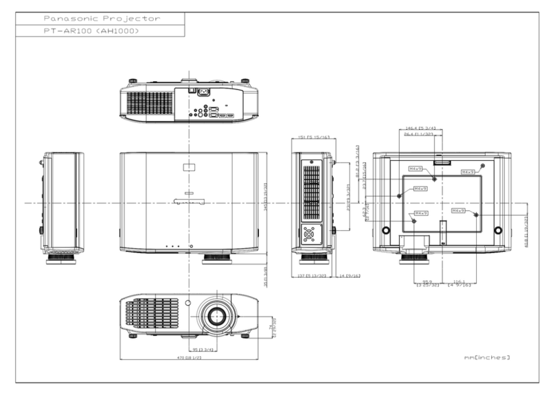
Panasonic PT-FW300NT System manual

Panasonic

Panasonic PT-FW300NT System manual

Panasonic PTLB20NTU - PROJECTOR- NETWORK IB User manual

Panasonic

Panasonic PTLB20NTU - PROJECTOR- NETWORK IB User manual

Panasonic PT-LB51NTE User manual

Panasonic

Panasonic PT-LB51NTE User manual

Panasonic PTAE100U - LCD PROJECTOR User manual

Panasonic

Panasonic PTAE100U - LCD PROJECTOR User manual

Panasonic PT-RZ660 User manual

Panasonic

Panasonic PT-RZ660 User manual

Panasonic PT-LX22 System manual

Panasonic

Panasonic PT-LX22 System manual

Panasonic PT-AE1000E Use and maintenance manual

Panasonic

Panasonic PT-AE1000E Use and maintenance manual

Panasonic PT-EX16KE User manual

Panasonic

Panasonic PT-EX16KE User manual

Panasonic TC-LT1 Series User manual

Panasonic

Panasonic TC-LT1 Series User manual

Panasonic PTL556U - LCD PROJECTOR User manual

Panasonic

Panasonic PTL556U - LCD PROJECTOR User manual

Panasonic PT-D9510U User manual

Panasonic

Panasonic PT-D9510U User manual

Panasonic PT-LW25H Guide

Panasonic

Panasonic PT-LW25H Guide

Panasonic PT-D5000E User manual

Panasonic

Panasonic PT-D5000E User manual

Panasonic PT-LX300E User manual

Panasonic

Panasonic PT-LX300E User manual

Panasonic PLC-XU75A User manual

Panasonic

Panasonic PLC-XU75A User manual

Panasonic PT-RZ475 series User manual

Panasonic

Panasonic PT-RZ475 series User manual

Panasonic PT-JW130FBE Operating instructions

Panasonic

Panasonic PT-JW130FBE Operating instructions

Panasonic PT-DZ570U User manual

Panasonic

Panasonic PT-DZ570U User manual

Panasonic PT-LB2U PT-LB1E User manual

Panasonic

Panasonic PT-LB2U PT-LB1E User manual

Panasonic PTD995U - LCD PROJECTOR User manual

Panasonic

Panasonic PTD995U - LCD PROJECTOR User manual

Popular Projector manuals by other brands

NEC PE506UL user manual

NEC

NEC PE506UL user manual

Digital Projection dVision 30 user guide

Digital Projection

Digital Projection dVision 30 user guide

Yamaha OneHome LPX-510 Installation overview

Yamaha

Yamaha OneHome LPX-510 Installation overview

Xiaomi Pro 2 user manual

Xiaomi

Xiaomi Pro 2 user manual

Eiki QXXAVC922---P owner's manual

Eiki

Eiki QXXAVC922---P owner's manual

Samsung SP-LSP9TGA E-manual

Samsung

Samsung SP-LSP9TGA E-manual

Planar PR5030 user manual

Planar

Planar PR5030 user manual

3M Multimedia Projector MP8750 Operator's guide

3M

3M Multimedia Projector MP8750 Operator's guide

Sharp XR-30X - XGA DLP Projector Operation manual

Sharp

Sharp XR-30X - XGA DLP Projector Operation manual

Dell 1609WX - WXGA DLP Projector user guide

Dell

Dell 1609WX - WXGA DLP Projector user guide

Epson EX5210 Specifications

Epson

Epson EX5210 Specifications

Epson Megaplex MG-50 Quick setup guide

Epson

Epson Megaplex MG-50 Quick setup guide

JVC D-ILA DLA-RS45 specification

JVC

JVC D-ILA DLA-RS45 specification

Sanyo PDG-DXL100 - XGA DLP Projector Notice

Sanyo

Sanyo PDG-DXL100 - XGA DLP Projector Notice

Sharp XG-XVI E/A Service manual

Sharp

Sharp XG-XVI E/A Service manual

AMCON EQ-6002 user manual

AMCON

AMCON EQ-6002 user manual

ViewSonic PJD6251 VS12585 Specification sheet

ViewSonic

ViewSonic PJD6251 VS12585 Specification sheet

Hitachi CP-X955W/E operating guide

Hitachi

Hitachi CP-X955W/E operating guide

manuals.online logo
manuals.online logoBrands
  • About & Mission
  • Contact us
  • Privacy Policy
  • Terms and Conditions

Copyright 2025 Manuals.Online. All Rights Reserved.