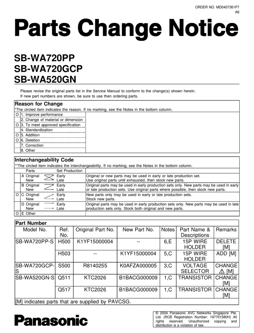
Panasonic SB-WA340 User manual
Other Panasonic Subwoofer manuals

Panasonic
Panasonic SB-WA15E User manual

Panasonic
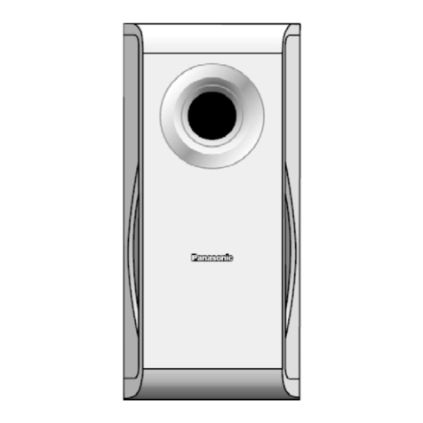
Panasonic SB-WA500PP User manual
Panasonic
Panasonic SB-W40P User manual

Panasonic
Panasonic SB-WA885EE User manual

Panasonic
Panasonic SB-WA330GCS User manual

Panasonic
Panasonic SB-AS40 User manual

Panasonic
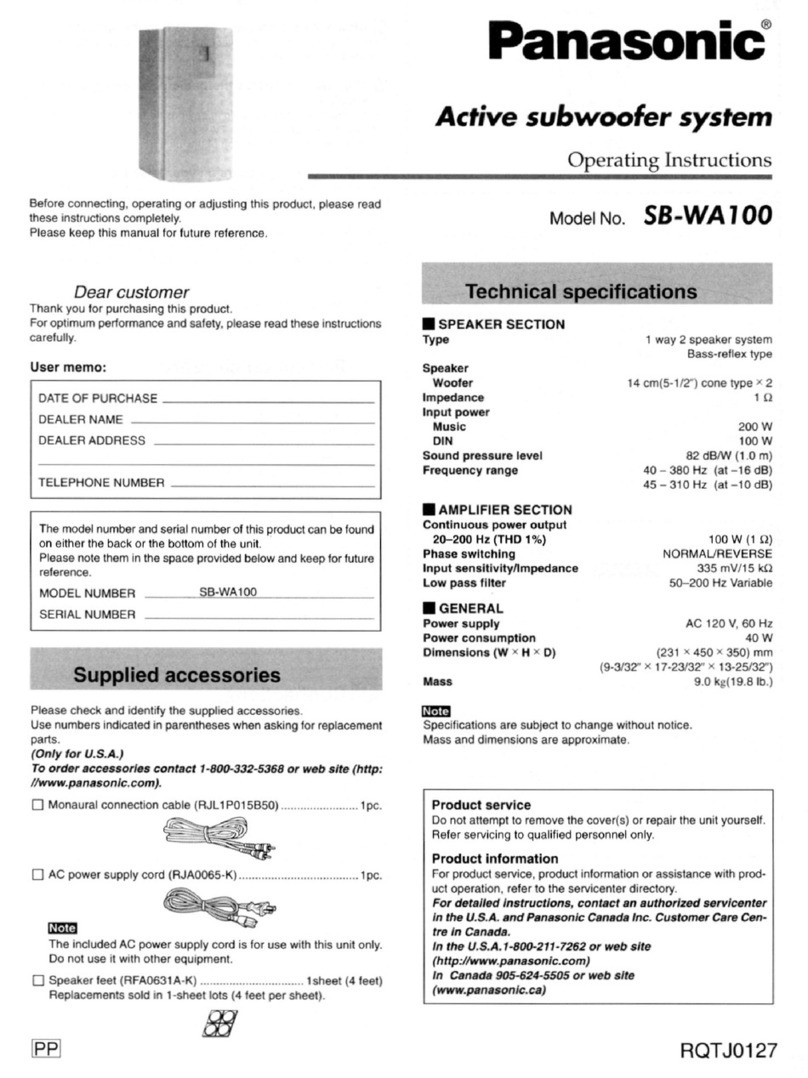
Panasonic SB-WA730PP User manual
Panasonic
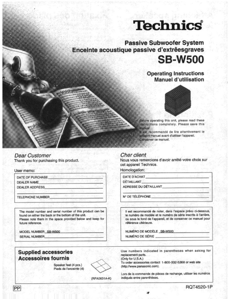
Panasonic SB-WA100 User manual
Panasonic
Panasonic SBW500 - SUBWOOFER SYS User manual

Panasonic
Panasonic SB-WA870EB User manual

Panasonic
Panasonic SBW500 - SUBWOOFER SYS User manual

Panasonic
Panasonic SB-WA840 User manual

Panasonic
Panasonic SB-AS100 User manual

Panasonic
Panasonic SB-WA340EBS1 User manual
Panasonic
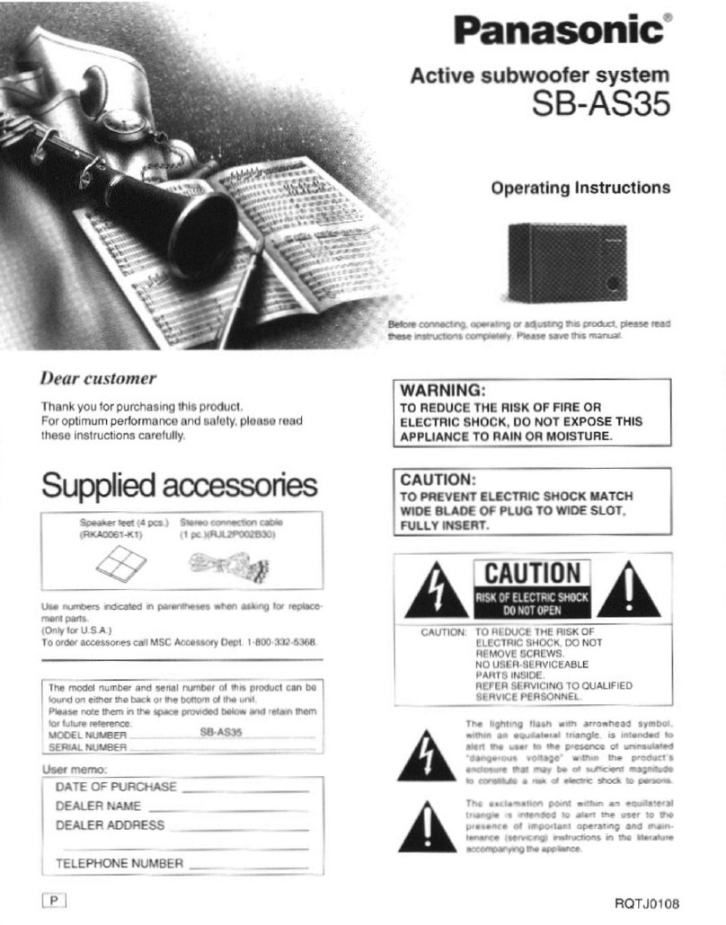
Panasonic SB-AS35 User manual

Panasonic
Panasonic SB-WA05E User manual

Panasonic
Panasonic SB-WA17E User manual

Panasonic
Panasonic SB-WA310P User manual
Panasonic
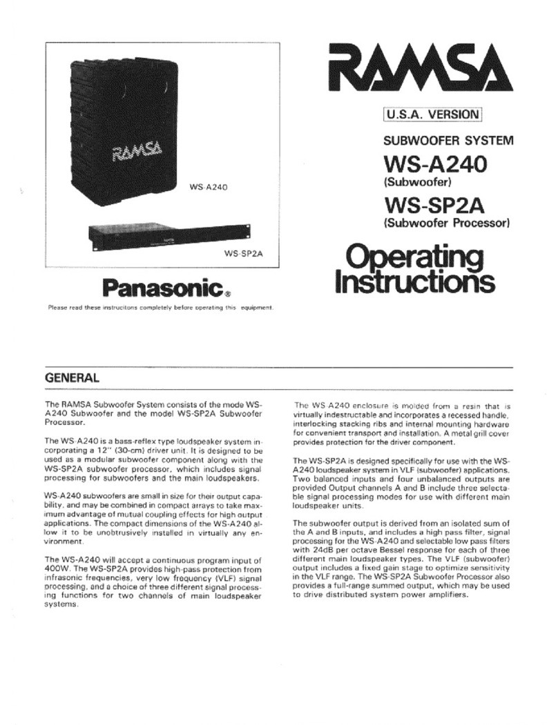
Panasonic Ramsa WS-A240 User manual

Panasonic
Panasonic SB-WA730GCP User manual
