manuals.online logo
Brands
  1. Home
  2. •
  3. Brands
  4. •
  5. Panasonic
  6. •
  7. VCR System
  8. •
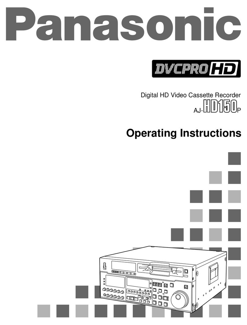
  9. Panasonic AJ-HD150FE User manual

Panasonic AJ-HD150FE User manual

Other Panasonic VCR System manuals

Panasonic NV-HD660 EG User manual

Panasonic

Panasonic NV-HD660 EG User manual

Panasonic AG-W3P User manual

Panasonic

Panasonic AG-W3P User manual

Panasonic Omnivision PV-7452 User manual

Panasonic

Panasonic Omnivision PV-7452 User manual

Panasonic NV-SJ230A User manual

Panasonic

Panasonic NV-SJ230A User manual

Panasonic NV-HD90 User manual

Panasonic

Panasonic NV-HD90 User manual

Panasonic Omnivision PV-4617 User manual

Panasonic

Panasonic Omnivision PV-4617 User manual

Panasonic AG5210 - VIDEO CASSETTE RECORDER User manual

Panasonic

Panasonic AG5210 - VIDEO CASSETTE RECORDER User manual

Panasonic NV-MV20GC User manual

Panasonic

Panasonic NV-MV20GC User manual

Panasonic AJD220P - DVC PRO User manual

Panasonic

Panasonic AJD220P - DVC PRO User manual

Panasonic NV-HD630A/EA/AM/BD User manual

Panasonic

Panasonic NV-HD630A/EA/AM/BD User manual

Panasonic NV-FJ600A User manual

Panasonic

Panasonic NV-FJ600A User manual

Panasonic Omnivision PV-8401 User manual

Panasonic

Panasonic Omnivision PV-8401 User manual

Panasonic Omnivision PV-V4620 User manual

Panasonic

Panasonic Omnivision PV-V4620 User manual

Panasonic AJ-D750P User manual

Panasonic

Panasonic AJ-D750P User manual

Panasonic NV-HS1000EC User manual

Panasonic

Panasonic NV-HS1000EC User manual

Panasonic NV-8200 User manual

Panasonic

Panasonic NV-8200 User manual

Panasonic Omnivision VHS PV-4905 User manual

Panasonic

Panasonic Omnivision VHS PV-4905 User manual

Panasonic NV-SJ200 Series User manual

Panasonic

Panasonic NV-SJ200 Series User manual

Panasonic NV-HS860EE-S User manual

Panasonic

Panasonic NV-HS860EE-S User manual

Panasonic NV-FJ620 User manual

Panasonic

Panasonic NV-FJ620 User manual

Panasonic NV-MV41 Series User manual

Panasonic

Panasonic NV-MV41 Series User manual

Panasonic NV-SJ4130PN User manual

Panasonic

Panasonic NV-SJ4130PN User manual

Panasonic AGDTL1P - TIME LAPSE RECORDER User manual

Panasonic

Panasonic AGDTL1P - TIME LAPSE RECORDER User manual

Panasonic ProLine AG-1980P User manual

Panasonic

Panasonic ProLine AG-1980P User manual

Popular VCR System manuals by other brands

RCA VR678HF user guide

RCA

RCA VR678HF user guide

Zenith VRL4270HF Operating guide & warranty

Zenith

Zenith VRL4270HF Operating guide & warranty

Akai VS-606EA Operator's manual

Akai

Akai VS-606EA Operator's manual

FUNAI 27C-450 Service manual

FUNAI

FUNAI 27C-450 Service manual

Sanyo VHR-M262EV Service manual

Sanyo

Sanyo VHR-M262EV Service manual

Sony SLV-X37 operating instructions

Sony

Sony SLV-X37 operating instructions

JVC SR-VS20U - Dual Format S-vhs/minidv Recorder instructions

JVC

JVC SR-VS20U - Dual Format S-vhs/minidv Recorder instructions

Grundig GV 7400 EURO Service manual

Grundig

Grundig GV 7400 EURO Service manual

Zenith VCM321 Installation and operating guide

Zenith

Zenith VCM321 Installation and operating guide

JVC HR-A43U, HR-A63U instructions

JVC

JVC HR-A43U, HR-A63U instructions

Aiwa VX-S135U operating instructions

Aiwa

Aiwa VX-S135U operating instructions

RCA VR725HF user guide

RCA

RCA VR725HF user guide

JVC 0703-AH-PJ-BJ instruction manual

JVC

JVC 0703-AH-PJ-BJ instruction manual

TruTech ZV450TT8 owner's manual

TruTech

TruTech ZV450TT8 owner's manual

JVC HR-DVS1EK instructions

JVC

JVC HR-DVS1EK instructions

Sensory Science DDV2120 user guide

Sensory Science

Sensory Science DDV2120 user guide

JVC HR-VP78U instructions

JVC

JVC HR-VP78U instructions

RCA VR611HF user guide

RCA

RCA VR611HF user guide

manuals.online logo
manuals.online logoBrands
  • About & Mission
  • Contact us
  • Privacy Policy
  • Terms and Conditions

Copyright 2025 Manuals.Online. All Rights Reserved.

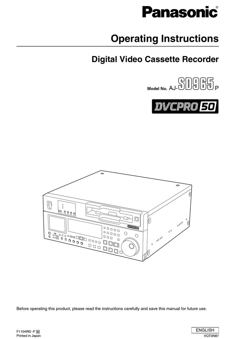
Operating Instructions
Digital HD Video Cassette Recorder
AJ- FE
– 2 –
Caution for AC Mains Lead
FOR YOUR SAFETY PLEASE READ THE FOLLOWING TEXT AREFULLY.
This roduct is equi ed with 2 ty es of AC mains cable. One is for continental Euro e, etc. and the other one is only
for U.K.
A ro riate mains cable must be used in each local area, since the other ty e of mains cable is not suitable.
FOR U.K. ONLY
This a liance is su lied with a moulded three in
mains lug for your safety and convenience.
A 13 am fuse is fitted in this lug.
Should the fuse need to be re laced lease ensure that
the re lacement fuse has a rating of 13 am s and that
it is a roved by ASTA or BSI to BS1362.
Check for the ASTA mark Ï or the BSI mark Ì on the
body of the fuse.
If the lug contains a removable fuse cover you must en-
sure that it is refitted when the fuse is re laced.
If you lose the fuse cover the lug must not be used un-
til a re lacement cover is obtained.
A re lacement fuse cover can be urchased from your
local Panasonic Dealer.
IF THE FITTED MOULDED PLUG IS UNSUITABLE FOR
THE SOCKET OUTLET IN YOUR HOME THEN THE
FUSE SHOULD BE REMOVED AND THE PLUG CUT
OFF AND DISPOSED OF SAFELY. THERE IS A DAN-
GER OF SEVERE ELECTRICAL
SHOCK IF THE CUT OFF PLUG IS INSERTED INTO
ANY 13 AMP SOCKET.
If a new lug is to be fitted lease observe the wiring
code as shown below.
If in any doubt lease consult a qualified electrician.
WARNING: THIS APPLIANCE MUST BE EARTHED.
IMPORTANT: The wires in this mains lead are coloured
in accordance with the following code:
Green-and-Yellow: Earth
Blue: Neutral
Brown: Live
FOR ONTINENTAL EUROPE, ET .
Not to be used in the U.K. FOR U.K. ONLY
If the lug su lied is not suitable for your socket outlet,
it should be cut off and a ro riate one fitted.
As the colours of the wires in the mains lead of this
a liance may not corres ond with the coloured mark-
ings identifying the terminals in your lug, roceed as
follows:
• The wire which is coloured GREEN-AND-YELLOW
must be connected to the terminal in the lug which is
marked with the letter E or by the Earth symbol Ó or
coloured GREEN or GREEN-AND-YELLOW.
• The wire which is coloured BLUE must be connected
to the terminal in the lug which is marked with the let-
ter N or coloured BLACK.
• The wire which is coloured BROWN must be con-
nected to the terminal in the lug which is marked with
the letter L or coloured RED.
How to replace the fuse
1. O en the fuse com artment with a screwdriver.
2. Re lace the fuse.
Fuse
For your safety
– 3 –
AUTION:
TO REDU E THE RISK OF FIRE OR SHO K
HAZARD, AND ANNOYING INTERFEREN E,
USE THE RE OMMENDED A ESSOIRES
ONLY.
AUTION:
TO REDU E THE RISK OF FIRE OR SHO K
HAZARD, REFER MOUNTING OF THE OP-
TIONAL BOARD TO AUTHORISEDSERVI E
PERSONNEL.
AUTION:
Do not install or lace this unit in a bookcase, built in
cabinet or in another confined s ace in order to kee
well ventilated condition. Ensure that curtains and any
other materials do not obstruct the ventilation condition
to revent risk of electric shock or fire hazard due to
overheating.
∫THIS APPARATUS MUST BE EARTHED
To ensure safe o eration the three- in lug must be
inserted only into a standard three- in ower oint
which is effectively earthed through the normal house-
hold wiring.
Extension cords used with the equi ment must be
three-core and be correctly wired to rovide con-
nection to earth. Wrongly wired extension cords are a
major cause of fatalities.
The fact that the equi ment o erates satisfactorily
does not im ly that the ower oint is earthed and that
the installation is com letely safe. For your safety, if in
any doubt about the effective earthing of the ower
oint, consult a qualified electrician.
∫DO NOT REMOVE PANEL OVER BY UNS REW-
ING
To reduce the risk of electric shock, do not remove
cover. No user serviceable arts inside.
is the safety information.
Operating precaution
O eration near any a liance which generates strong
magnetic fields may give rise to noise in the video and au-
dio singals. If this should be the case, deal with the situa-
tion by, for instance, moving the source of the magnetic
fields away from the unit before o eration.
WARNING:
TO REDU E THE RISK OF FIRE OR SHO K
HAZARD, KEEP THIS EQUIPMENT AWAY FROM
ALL LIQUIDS-USE AND STORE ONLY IN LO A-
TIONS WHI H ARE NOT EXPOSED TO THE
RISK OF DRIPPING OR SPLASHING LIQUIDS,
AND DO NOT PLA E ANY LIQUID ONTAIN-
ERS ON TOP OF THE EQUIPMENT.
■Do not insert fingers or any objects into the video
cassette holder.
■Avoid o erating or leaving the unit near strong
magnetic fields. Be es ecially careful of large audio
s eakers.
■Avoid o erating or storing the unit in an excessively
hot, cold, or dam environment as this may result in
damage both to the recorder and to the ta e.
■Do not s ray any cleaner or wax directly on the unit.
■If the unit is not going to be used for a length of time,
rotect it from dirt and dust.
■Do not leave a cassette in the recorder when not in
use.
■Do not block the ventilation slots of the unit.
■Use this unit horizontally and do not lace anything on
the to anel.
■Cassette ta e can be used only for one-side, one
direction recording. Two-way or two-track recordings
cannot be made.
■White recording.
■Do not attem t to disassemble the recorder.
There are no user serviceable arts inside.
■If any liquid s ills inside the recorder, have the recorder
examined for ossible damage.
■Refer any needed servicing to authorized service
ersonnel.
AUTION:
Even when the Power Switch is in the OFF
position, a small current flows the filter circuit.
Cassette ta e can be used for either Colour or Black &
AUTION
TO REDUCE THE RISK OF FIRE OR SHOCK
HAZARD, REFER CHANGE OF THE SWITCH
SETTING INSIDE THE UNIT TO AUTHORIZED
SERVICE PERSONNEL.
IMPORTANT
“Unauthorized recording of copyright television
programmes, video tapes and other materials may
infringe the right of copyright owners and be con-
trary to copyright law.”
For your safety
– 4 –
Variable memory function.........................................57
ERROR LOG function ..............................................58
Setu (default settings) ...........................................60
Setu menus ............................................................61
•SYSTEM menu .....................................................65
•USER menu ...........................................................68
• BASIC menu ......................................................68
• OPERATION menu ............................................72
• INTERFACE menu .............................................76
• EDIT menu .........................................................78
• TAPE PROTECT menu ......................................81
• TIME CODE menu .............................................82
• VIDEO menu ......................................................84
• AUDIO menu ......................................................89
• MENU menu .......................................................96
Time code/user bit ...................................................97
Recording internal/external time codes ...................98
Re roducing the time code/user bit ........................99
Su erim ose screen .............................................100
Audio recording channel and monitor
out ut selection ....................................................101
Rack mounting ......................................................102
Video head cleaning ..............................................103
Condensation ........................................................103
Error messages .....................................................104
Table of AUTO OFF Error messages ....................106
RS-232C interface .................................................108
Connector signals .................................................115
Printed circuit board ..............................................117
S ecifications ........................................................118
For your safety ...........................................................2
General and Features ...............................................5
Controls and their functions ......................................7
•Front anel ..............................................................7
•Connector area .....................................................16
O erations using the front anel bottom controls ....19
O erations using the front anel to controls ..........22
Connections .............................................................26
Ta es .......................................................................27
Switching on the ower/inserting the cassette .........28
STOP/STAND BY mode ..........................................29
Recording ................................................................30
Playback ..................................................................31
Jog/shuttle ...............................................................32
Manual editing .........................................................33
Preroll ......................................................................34
Automatic editing (deck to deck) .............................35
•Switch settings and adjustments ...........................36
•Selecting the editing mode ....................................37
•Entering the edit oints .........................................38
•Checking the edit oints ........................................39
•Modifying the edit oints .......................................40
•Preview .................................................................41
•Executing automatic editing ..................................42
•Review ..................................................................43
Audio s lit editing ....................................................44
Ex ansion mode execution using the MODE/SEL
button .....................................................................46
MULTI CUE function ................................................47
IC CARD function.....................................................53
ontents
Before operating this unit, check that all of its accessories are present and accounted for.
Power cord....1 c
Options
• AJ-MA75P Rack mounting ada ter
• AJ-UDC150AP HD-SD format converter
– 5 –
General and Features
This unit is a DVCPRO HD format HD digital video cassette recorder which is designed to
use 1/4-inch wide com act cassette ta es.
It is a studio-use digital VTR which can record, lay back and edit HD signals (1080i, 59.94
Hz/60 Hz), and can lay back ta es recorded using the existing DVCPRO (25 Mb s/50
Mb s) format. Use of the HD-SD conversion facility of the o tional format converter enables
interfacing with existing SD systems and develo ment into HD systems. This VTR with its
high icture quality uses high-efficiency digital com ression technology to reduce by a
significant margin the degree of deterioration in the sound and icture quality which
accom anies dubbing.
The unit features a com act 4U size and lightweight design to make it easier to carry around.
It can also be easily installed in a 19-inch rack.
The settings for the unit’s setu are erformed interactively while viewing the dis lay tube at
the to front of the unit or the screen menus shown on a TV monitor. Both assemble and
insert editing facilities are rovided as editing functions.
Features ompact size and light weight
This is a 4U digital VTR. Using the rack-mounting ada ters (o tional accessory: AJ-MA75P),
it can also be easily housed in a 19-inch rack.
Up to 46 minutes of recording
The L-size cassettes (max. 46 minutes) are used for recording. The ta e is 1/4-inch in width,
which makes for a com act design.
High picture quality
The unit’s high icture quality is achieved by 4:2:2 HD com onent signal recording using a
recording rate (100 Mb s) which is 4 times higher than that of the existing DVCPRO format.
1080i/720p, 59.94 Hz/60 Hz signal switching
By a rocess of automatic switching to match the video in ut signals, each ty e of signal can
be recorded and layed back.
SDI interface
The unit comes with an HD serial digital interface as a standard accessory.
ompatibility with DV PRO
The unit can lay back ta es which have been recorded using the existing DVCPRO (25
Mb s/50 Mb s) format.
Furthermore, consumer-use DV ta es (SP) can also be layed back on the unit.
Digital slow motion/dial jog
Clear layback at s eeds of -1× through to +1× are made ossible with Panasonic’s own
digital-slow technology.
<Note>
Some noise may occur during slow layback (using the external controller) at s eeds almost
exactly +1× or -1×.
Search speed
Search s eed enables the ta e to be layed back with colour images at a s eed of u to 50
times the forward and reverse direction.
– 6 –
General and Features
Features
(continued) Time codes
This unit comes with a built-in time code generator (TCG)/time code reader (TCR). In
addition to the internal time code, an external time code can also be recorded as the LTC on
the unit’s ta e.
Multi-functional interfaces
• Serial digital input and output connector
The unit features a HD com onent serial interface in ut/out ut connector to enable HD
com onent video signals and 8-channel digital audio signals to be interfaced using just the
one BNC connector. (SMPTE292M/BTA S-004)
It is also ossible to out ut SD com onent serial signals rovided that the HD-SD format
converter board (o tional accessory) is installed. (SMPTE259M-C, 272M, 294M)
• Analogue video output connector
Com osite out ut connectors are rovided as a standard feature. They out ut com osite
signals during DVCPRO reci rocal layback, DV layback or down-conversion. At all other
times, they out ut the black burst signal.
• AES/EBU audio input/output connectors
Digital audio in ut/out ut connectors for 8 channels are featured as a standard accessory.
• 9-pin RS-422A and RS-232 remote control connectors
In addition to the standard 9- in serial remote (RS-422A) control connector, the unit is
equi ed with RS-232C and 50- in arallel remote control connectors.
The RS-422A facility enables arallel o eration if a loo connection has been erformed
between the unit and another VTR.
8-channel high-sound-quality digital audio
The 8-channel PCM audio allows for not only inde endent editing and mixing on all eight
channels. One channel is rovided for the analogue CUE track.
Menu-driven setup
The setu settings, which are conducted rior to o erating the unit are erformed while
viewing the setu menus either on the unit’s dis lay or a TV monitor.
– 7 –
ontrols and their functions
Front panel
SET UP PROG
123
MENU
SAVE/
PROG MENU
MENU SET DIAG
EXIT
STATUS STATUS
1234
=
>
<
?
@
A
B
C
D
E
F
GHIJ
K
L
TU
SRQ
VW
XY
Z
abc df
123
45678
9:
;
M
N
O
P
[
\
]
^
_
`
g h
ON
AUDIO CH SELECT
SHIFT ADJ
TC SET
START
TC/CTL
RESET
TC INT
TC
TAPE
UB
STAND BY
EDIT PLAY
REW STOP
SERVO
REC
FF
REC INHIBIT
PLAYER
EXT EE
MODE
REMOTE
PUSH
REV FWD
RECORDER
LOCAL
CONTROL
CH
1
1
ASMBL
PREVIEW
REVIEW
AUTO EDIT
PREROLL
TRIM
A
IN
IN
SET OUT
A
OUT
MULTI UE INSERT
VIDEO
H1/5 H2/8 H3/7 H4/8 UE T
CH
4
OFF
POWER CH CONDITION ENTER ESCAPE SHIFT
METER
FULL/FINE
MONITOR SELECT
LEVEL
HEADPHONES
CH 1/5 CH 2/6 CH 3/7 CH 4/8 CUE
REC
L
R
PB
PULL FOR VARIABLE
PULL
OPEN PULL
OPEN
CH
5
CH
8
2 3 4 5 6 7 8
JOG SHTL
SLOW
EJE T
M
-
cassette
/
ADAPTER
Caution: Do not insert S-cassette without ada ter
MODE/SEL EXIT
– 8 –
ontrols and their functions
<Front Panel Top Section>
1POWER switch
2TV system/format displays
This shows the format during layback.
HD: This indicates that the ta e is recorded or layed back in the DVCPRO HD format.
50 M: This indicates that the ta e is layed back in the DVCPRO (50 Mb s) format.
25 M: This indicates that the ta e is layed back in the DV or DVCAM mode of the
DVCPRO (25 Mb s) format.
33
33
3VTR status display area
The VTR’s statuses, rogrammable menus and setu menus a ear in this dis lay area.
<Status display>
This indicates the VTR statuses (format, field frequency, video/audio in uts, time code,
etc.) which have been defined by the user on the front sub- anel.
<Programmable menu display>
The setu menus which have been defined by the user are dis layed on the front sub-
anel. Settings can be changed using the 5, 6, 7 and 8 buttons.
<Setup menu display>
The setu menus are dis layed using the MENU d button.
44
44
4hannel condition lamps
One of these lam s lights in accordance with the error rate status. (Green→Amber→Red)
Green: This lights when the error rates for the video and audio layback signals are both
acce table.
Amber: This lights when the error rate for the video or audio layback signals has
deteriorated.
The layback icture will remain normal even when this lam lights.
Red: This lights when the video or audio signals are subject to rectification or
inter olation.
55
55
5Scroll buttons
These are used for left and right scrolling when the status is dis layed in the VTR status
dis lay area.
They are used for u and down scrolling when the rogrammable menu is dis layed in the
VTR status dis lay area.
66
66
6ENTER button
Press this to enter the menu items or the settings when the rogrammable menu is
dis layed.
7 7
7 7
7 ES APE button
Press this to ignore or cancel the settings when the rogrammable menu is dis layed.
88
88
8 SHIFT button
The values of rogrammable menu settings can be changed at high s eed by ressing the
scroll buttons while holding down the SHIFT button.
9assette insertion slot
::
::
:EJE T button
When this is ressed, the ta e is unloaded and several seconds later the cassette is
automatically ejected. When the counter dis lay indicates “CTL”, the dis lay is reset.
;AUTO OFF lamp
This lights when trouble has arisen in the deck’s o eration.
– 9 –
ontrols and their functions
<Front Panel entre Section>
<<
<<
<PLAY button
Playback commences when this button is ressed.
Recording commences when the button is ressed together with the REC button; manual
editing commences when it is ressed together with the EDIT button during layback.
However, manual editing will not be initiated if the servo is not locked.
Pressing only the PLAY button during manual editing will cut out the editing and establish
the layback mode.
==
==
=RE button
Recording commences when this button is ressed together with the PLAY button.
When it is ressed during layback, search*1), fast forward or rewind, EE mode images
and audio signals can be monitored for as long as it is ke t de ressed.
When it is ressed in the sto mode, EE mode images and sound can be monitored.
When the STOP button is ressed, the original icture and sound are restored.
>>
>>
>STOP button
When this is ressed, the ta e sto s travelling, and if the TAPE/EE selector switch is at
TAPE, still ictures can be monitored.
The drum continues to rotate even in the sto mode, and the ta e remains in close contact
with the drum.
If the sto mode continues for more than a certain eriod of time, the unit automatically
switches to the standby OFF mode in order to rotect the ta e.
The sto mode is established immediately after a cassette has been inserted into the unit.
??
??
?FF button*2)
The ta e is fast forwarded when this is ressed.
@@
@@
@REW button*2)
The ta e is rewound when this is ressed.
AA
AA
AEDIT button
For manual editing, ress both this button and the PLAY button together during layback.
When the button is ressed in the sto mode, the in ut mode signals selected by the
ASMBL or INSERT button can be monitored in the EE mode.
The original icture and sound are restored when the STOP button is ressed.
When the button is ressed during layback, search*1), fast forward or rewind, the in ut
signals of the mode selected by the ASMBL or INSERT button can be monitored in the EE
mode for as long as the button is held down.
BB
BB
BSERVO lamp
This lights when the drum servo and ca stan servo have locked.
CC
CC
CRE INHIBIT lamp
In the following situations, this lam lights u to indicate that recording and editing cannot be
erformed.
(Related setu menu items No.022, No.023, No.113, No.114, No.117 and No.118)
1. When 1 (ON) has been selected as the setu menu item No.113 (REC INH) setting
2. When the cassette has been set to the accidental erasure revention mode
3. When MANUAL has been selected as the setu menu No.022 (PB FORMAT), 50M/
25M/50M /DV/DVCAM has been selected as the menu No.023 (FORMAT SEL), ON
has been selected as the menu No.118 (SD MODE INH), and the ta e has been
inserted
4. When AUTO has been selected as the setu menu No.022 (PB FORMAT), ON has
been selected as the menu No.118 (SD MODE INH), and a DVCPRO, DVCPRO50,
DVCPRO50P, DV or DVCAM ta e has been inserted.
5. When ON has been selected as the setu menu No.117 (M CASSTT INH) and the M
cassette ta e has been inserted
*1) No guarantees are given for the audio layback sound in the search mode.
*2) The FF/REW s eed can be selected on the setu menu No. 102 (FF. REW MAX), and it is
set to the same s eed.
– 10 –
ontrols and their functions
<Front Panel entre Section>
DD
DD
DSTAND BY button
When this is ressed, the same tension as in the regular sto mode is a lied to the ta e,
and while the head drum continues to rotate, the button’s lam lights to indicate that the
standby ON mode is established.
In the standby OFF mode, the half-loading mode is established.
When this button is ressed in the sto mode, the standby OFF mode is established, the
half-loading mode is established. The lam in the button now goes off. When the unit
remains in the sto mode for longer than a redetermined eriod, the standby OFF mode
is automatically established in order to rotect the ta e.
When this button or the STOP button is ressed in the standby OFF mode, the standby
ON mode is established.
When a button other than the STOP button is ressed, the mode corres onding to the
button ressed is established.
On-screen settings are available for the transfer time to the standby OFF mode.
EE
EE
EPLAYER/RE ORDER buttons
These buttons are o erated when editing o erations are conducted using the unit as the
recorder and a VTR equi ed with an RS-422A serial interface remote control connector
(9 ins). Neither button functions when the unit is used on its own.
PLAYER button: When this button is ressed, its lam lights, and the layer connected
to the unit can be o erated by remote control. The unit’s editing and
ta e trans ort buttons now control the layer’s functions.
RE ORDER button: When this button is ressed, its lam lights, and the editing and ta e
trans ort buttons control the recorder’s (= the unit’s) functions.
Both lam s light, and the recorder functions as the master unit for Parallel Run o erations
if the PLAYER or RECORDER button is ressed while “ENA” has been selected for setu
menu No. 200 (PARA RUN). [However, external control can no longer be exercised from
the REMOTE connector (9- in) when this setting has been made.]
FF
FF
FT / TL switch
By ressing this switch, what a ears on the counter dis lay is changed between TC and
CTL.
When TC is selected, either the TC or UB value is dis layed de ending on the osition
selected by the TC/UB switch.
GG
GG
GT /UB switch
This selector switch determines whether the value of TC or UB a ears on the counter
dis lay when the TC/CTL switch has been set to TC.
HH
HH
HINT/EXT switch
INT: For using the built-in time code generator.
EXT: At this osition, the external time code which is in ut from the time code in ut
connector is used.
II
II
ITAPE/EE switch
<In the stop mode>
TAPE: For out utting the signals layed back from the ta e.
EE: For out utting the in ut signals selected by the setu menus No. 600 (VIDEO IN
SEL) and No. 700 (AUDIO IN SEL).
<In the editing*/recording mode>
TAPE: For out utting the simultaneous layback signals.
EE: For out utting the in ut signals selected by the setu menus No. 600 (VIDEO IN
SEL) and No. 700 (AUDIO IN SEL).
* The SETUP menu No. 302 (CONFI EDIT) setting is required.