Panchromatic Eumig P26 User manual

Panchromatic Eumig P26 User Manual
1
The Place to find Antique, Vintage, Retro or just plain used, 8 mm Super 8 mm 9.5 mm,
16 mm Film Projectors, Slide Transparency Projectors, Cameras and Darkroom
Equipment.
Eumig P26
8 mm Format
Film Projector
User Manual
Service@Panchromatic.co.uk

Panchromatic Eumig P26 User Manual
2
EUMIG SUPER PROJECTOR P 26
Fig.A

Panchromatic Eumig P26 User Manual
4
INSTRUCTIONS FOR USE
The EUMIG SUPER PROJECTOR P 26 is capable of projecting pictures of
utmost sharpness and brilliance it is fitted with a first class coated and
Interchangeable lens EUPRONAR f/1.4.
EUMIG P26 is suitable both for AC and DC mains, it is provided
especially for projection lamps of 500 Wafts 110 Volts (as f.i. Philips
Type 6152 C. socket P28, with cap). The pilot lamp (e. g. perfume
evaporator lamp 13 Watts, socket E 14, frosted if possible) must be of
the some voltage as the local supply.
Before using the projector, care must be taken that the voltage shown
on the top resistance corresponds exactly to that of the local supply.
There is only one exception to this rule, i.e. the top piece for 110 Volts
which not only allows the projector to be used on a mains tension of 110
Volts with any appropriate projection lamp 110 Volts up to 500 Watts
but also on a mains tension of 220 Volts with any appropriate projection
lamp of 220 Volts up to 500 Wafts.
A resistance for the motor only is housed in the base of the machine and
a slider 28 (as per Fig.B) is provided, by means of which this driving
motor may be adjusted to any mains tension of 110 to 240 Volts. In
order to insert the projection lamp, just lift the top piece 4(Fig.B) and fit
the lamp into the holder by pressing down and turning in a clockwise
direction. Plug 18 (Fig.B) serves for the connection of a table lamp, if
required; it is in contact only when switch 17 (Fig.A) is in the "off"
position.
MOUNTING OF SPOOL ARMS.
Open these out. engage the two projections in the slots in the body-
work of the projector and tighten up the screw 14 (Fig.B.) Be careful
that the pulleys of the spool arms are on the same side of the machine
as the corresponding driving pulleys, as can be seen in Fig.B. Now
mount the spring belts as shown in Fig.B.

Panchromatic Eumig P26 User Manual
5
ELECTRICAL CONNECTIONS AND GENERAL MANIPULATION.
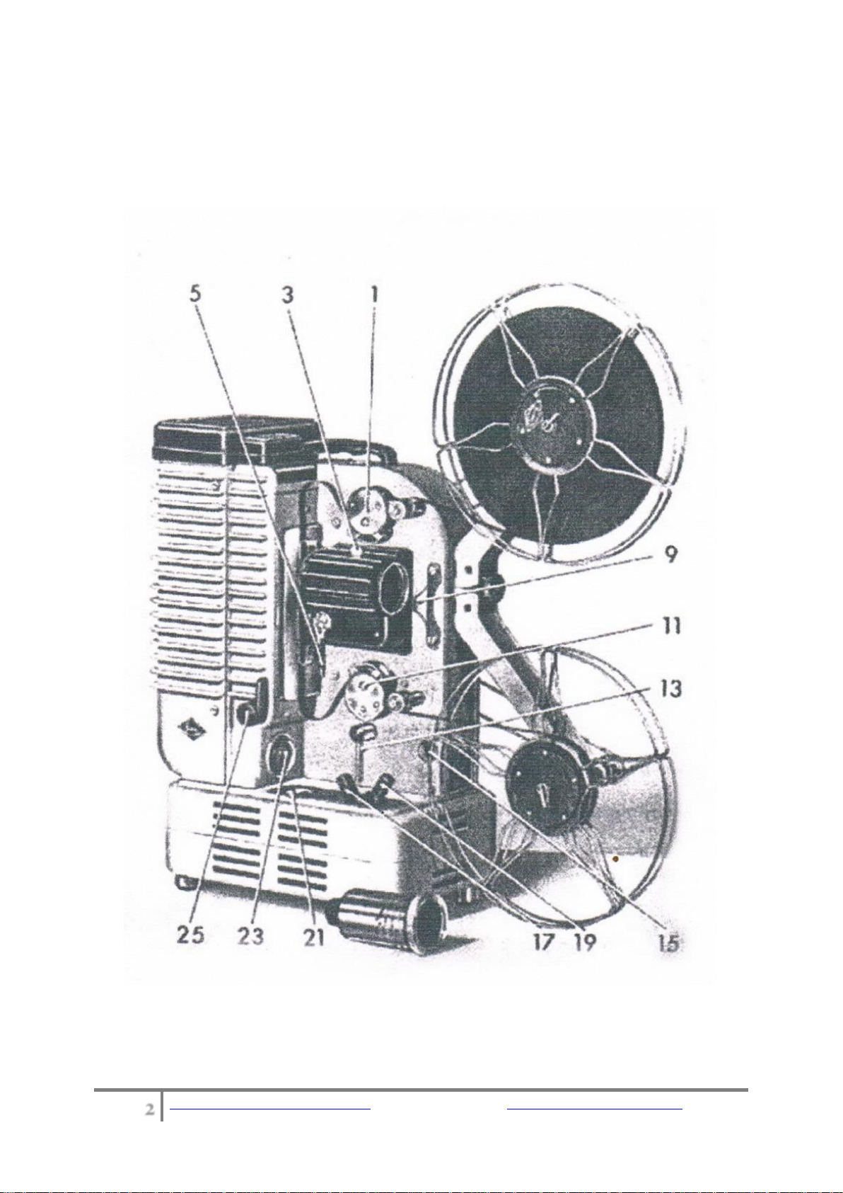
See that the switch 17 is in the "Off" position, as shown in Fig.A. The
connection cable with three cores which is supplied with the projector
and which allows earthing at the some time, if required, Is then
connected with plug 26 (Fig.B) on the reverse side of the machine.
When this is connected with the wall socket, the pilot lamp 23 (Fig.A) as
well as any table lamp that may be used, light up. They go out, when
switch 17 is switched on. On the reverse side of the projector, there Is
also a special switch 16 (Fig.B) which in the "-" (minus) position
switches on a resistance, provided in order to protect the projection
lamp, whereas in Its "+" (plus) position It gives the full voltage to the
lamp, thus obtaining a maximum output of tight. It is recommended to
start operation of the projector with the "minus" position of the switch.
The switch 17 (Fig.A) referred to above, switches on both projection
lamp and motor, while switch 15 (Fig.A) will set going the motor only
without the projection lamp lighting up. This switch serves for
respooling, for ventilation, or for a short trial run. The lever 21 (Fig.A)
varies the speed of the motor. Switch 19 (Fig.A) has positions for
forward and reverse motion and is provided for repeating a scene. The
lever 25 (Fig.A) operates a still picture device, while projection is re-
starled by turning back the same lever. When, in the still picture
position, the shutter remains closed, this is remedied by a slight turn of
the driving wheel 8(Fig.B). The handle 2 (Fig.B) on the reverse side of
the lamp casing enables the user to centre the lamp corredly, thus
obtaining the maximum light on the screen. Tilting is effected by the two
screws 24 (Fig.B) at the back of the projector.
LOADING THE FILM.
The loaded reel Is put on the topspool arm, making sure when a
projetor for 8 mm film is being used, that the little pin on the spool axle
engages itself in one of the holes provided for this purpose in the reel.
The 16mm type of projector is suitable for the projection of films
perforated either on both sides or on one side only.

Panchromatic Eumig P26 User Manual
6
Lead the film over the small guide roller and down below the top
sprocket 1(Fig.A), then pass it between the two guide plates, when a
gentle upward tension will engage the film with the sprocket teeth.
Open the film gate by turning the lever 5(Fig.A) under the lens
mounting the lens having been somewhat screwed out, if necessary,
and insert the film sideways into the gate, then close the gate. The film
is then passed around the bottom sprocket 11 (Fig.A). under the second
small guide roller on to the emply film spool. A loop must be left
between the top sprocket and the gate, while another loop is left before
passing the film around the bottom sprocket.
PROJECTION.
Having arranged the projector at on appropriate distance from the
screen, switch on by the lever 17 (Fig.A) and focus by turning the lens
mount. Adjust the speed by lever 21 (Fig.A) until all flicker is removed.
If parts of two pictures are to be seen on the screen, framing is effected
by turning the lever 13 (Fig.A), Stills, by turning the knob 25 (Fig.A),
may be shown for a longer or shorter space of time, according to the
kind of film used, an adequate cooling of the film being effected by a
newly designed, highly efficient fan. Moreover, a heat absorbing filter is
provided for the projection of still pictures.
REWINDING.
First place the lever 25 (Fig.A) Into the "still" position. Disconnect belt of
upper spool arm and place an the inner groove of the double pulley 12
(Fig.B). Remove the belt from the lower spool arm. The projector is
switched for forward motion by lever 19, (fig.A). Lead the film directly
from the lower to the upper, empty reel. Switch on with switch 15 (Fig.
A) and regulate speed of rewind by means of lever 21 (Fig.A).
MAINTENANCE.
The projector and especially the parts being in contact with the film,
must be kept scrupulously clean. To facilitate cleaning the entire gate
mechanism may be withdrawn by opening lever 5(Fig.A), but before
doing so, care must be taken to turn the main driving wheel 8(Fig.B)
until the dot marked on the same Is on the top. In this position the

Panchromatic Eumig P26 User Manual
7
claws are withdrawn and cannot be damaged. Now, press the gate
closed with the fingers and gently ease the unit forward and out,
without using any undue pressure.
The film gate, as well as the lens, the condenser and the reflector
should be cleaned with a very soft cloth or brush. For removing or
cleaning the lens, press away spring 3(Fig.A), which will then allow to
easily remove the lens.
Oiling of the projector should be done regularly after projection of every
3000 ft. of film or so. Interior bearings are lubricated from the central
point 6(Fig.8). (After removing the closing button) External points to be
lubricated are Indicated by red spots.
Cleaning and Oiling of the claw mechanism is easier, if the film gale is
removed. The little spring is pressed down on the spot marked by
number 9(Fig.A) and the entire tens holder is pulled out until there is a
distinct stop. (In order to avoid spattering the film with oil use the
smallest amount possible.)
Service@Panchromatic.co.uk
Table of contents
Other Panchromatic Projector manuals