P&H Electronics LA-400B User manual

P&H Electronics Model LA-400B Linear Amplifier
Manual Update by NA5RC Page 1 of 6
INTRODUCTION
This manual has been reproduced by James Lawrence, NA5RC, a LA-400B owner. There
are some notes on page 6 not associated with the manual. Where liberties are taken, they
are so noted.
GENERAL DESCRIPTION
The Model LA-400B Linear Amplifier is a grounded grid amplifier employing pentodes
connected as high mu triodes. This circuit design makes possible a compact, medium power
amplifier.
When used with a suitable exciter, this amplifier will deliver a high quality signal whether used
for single sideband, amplitude modulation, frequency modulation, or CW.
A variety of output impedances may be matched by the pi network output circuit; however, a
low impedance load is recommended. The low impedance input circuit is untuned. This
feature simplifies multiband operation. A well-filtered power supply incorporating full wave
mercury vapor rectifiers is employed. The cabinet housing this amplifier matches many
popular exciters. High quality components are used throughout.
SPECIFICATIONS
Power Rating 400 Watts P.E.P. Input
Drive Requirement 20 Watts for maximum output
Driver Impedance 52-72 Ω(The driver should employ link coupling or other
means for DC return.)
Frequency Range 75 thru 10 Meters
Output Impedance 50-75 Ωon all bands
Metering Circuit Indicates RF Voltage Input, Plate Current, and RF Amperes
Output
Tubes 2 ea Type 816 Rectifiers
4 ea Type 1625 (modified)
OPERATING INSTRUCTIONS
Preliminary
1. Connect the driver to the coax fitting at the rear of the unit marked RF Input using a
short length of coax.
WARNING: Do not apply plate power without a suitable driver connection.
2. Connect a 52-72 Ωantenna or load to the coax connector marked RF Output located
near the center of the rear deck.
3. Provision for blocking bias from exciter on Rear Deck if desired (See Figure 1).
4. Plug the line cord into any 105-125 volt 50/60 cycle A.C. source.
5. Apply filament voltage and wait at least 60 seconds before any attempt is made to
apply plate voltage.

P&H Electronics Model LA-400B Linear Amplifier
Manual Update by NA5RC Page 2 of 6
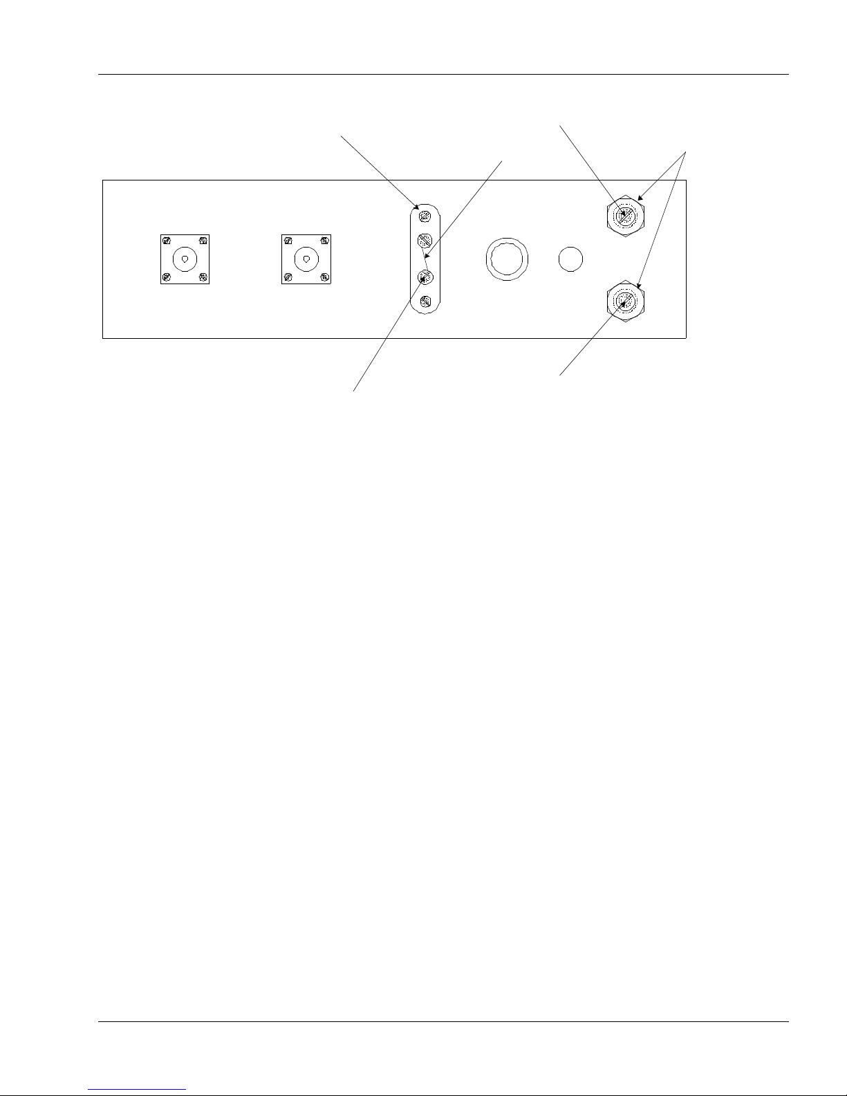
Tuning
Meter Switch in position:
•No. 1 indicates RF Voltage input: 0-50 Volts
•No. 2 indicates plate current: 0-500 mA
•No. 3 indicates RF Current Output: 0-5 Amperes
Maximum inductance is obtained with the rotor indicator in the extreme left position.
Maximum tuning capacitance is obtained with the indicator on the skirt of the tuning knob at
the extreme left.
Maximum loading capacitance is obtained with the indicator on the skirt of the loading knob at
the extreme left.
Maximum coupling capacitance is in position No. 1.
For Inductance, use the following:
•75 Meters: maximum inductance
•40 Meters: half the inductance
•20 Meters: one quarter the inductance
•15 Meters: one eighth the inductance
•10 Meters: adjust roller for maximum output on the last turn of the inductor.
Procedure (clarified from original)
1. Set tuning inductor for desired band.
2. Set tuning and loading capacitor to maximum capacity positions.
3. Set coupling switch to #1.
4. Set meter switch to #3.
5. Apply plate Voltage.
6. Insert approximately ten Watts of driving power for tuning.
7. Resonate the tuning capacitor and reduce the loading capacity until a reading is
obtained. It may be that no reading will be obtained on higher frequencies. In this
case, change the coupling switch to position No. 2 or 3.
8. Adjust tuning, loading, and coupling controls for maximum RF output. The inductance
may be varied at this time for additional output. Remove either the drive or plate
voltage before changing the inductor setting.
The amplifier is now ready for operation. If a two-tone test signal and an oscilloscope are
available, the output of the amplifier may be observed to determine if the tuning is correct.
Over-coupling or a high standing wave ratio may introduce distortion.
The point at which decreasing the inductance or decreasing the loading or coupling
capacitance gives no apparent increase in output is the point where best linearity is obtained.
The tuning procedure is the same for CW, AM, FM, PM, and SSB.

P&H Electronics Model LA-400B Linear Amplifier
Manual Update by NA5RC Page 3 of 6
Figure 1: Chassis - Rear View
A
B
RF
OUTPUT
RF
INPUT
BIAS STRIP
FUSE AC
LINE
METER ADJUST
POTS
GROUND
JUMPER
RF VOLTS
RF AMPS
Blocking Bias
If external bias (such as from the Central Electronics 20A exciter) is used, the -100V should
be connected to terminal A on the bias strip and the jumper between terminals A and B
removed.
Where external bias is not desired, the jumper should remain between terminals A and B.
Meter Adjustments
The meter calibrating controls are preset at the factory and under normal use do not need to
be touched. However, if the RF voltage and current readings appear to be in error, they may
be checked and recalibrated in the following manner.
1. RF Voltage Input
With the meter switch set at position #1, connect a coaxial T connector to the RF input of the
LA-400B. One side of the T is connected to the exciter and the other side is connected to an
RF voltmeter, 0-50 Volts.
With carrier inserted at the exciter, the meter on the LA-400B should read the same as on the
RF voltmeter. If it does not, adjust the potentiometer marked "R.F. VOLTS" so that the two
meters read the same.
2. RF Amperes Output
With the meter switch set at position #3, connect an RF ammeter in series with the RF output
and a 52-70 Ωdummy load. Insert carrier at the exciter and note whether the RF ammeter
and the meter on the LA-400B read the same. If they do not, adjust the potentiometer
marked "R.F. AMPS" so that the two meters read the same.

P&H Electronics Model LA-400B Linear Amplifier
Manual Update by NA5RC Page 4 of 6
MODEL LA-400B PARTS LIST
ITEM
QTY
DESCRIPTION
C1, C2, C3, C4, C10, C11, C13,
C15, C16, C17, C18, C19, C20
13
0.005 mFd, 500 V
C5
1
0.004 mFd, 5000 V
C6
1
150 mmFd, Variable
C7
1
400 mmFd, Variable
C8
1
680 mmFd, Silver Mica
C9
1
330 mmFd, Silver Mica
C12, C21
2
0.005 mFd, 5000 V
C14
1
? mmFd, 1000 V
R1
1
1000 Ω, 2 W
R2
1
12 KΩ, 2 W
R3
1
1.2 KΩ, 2 W
R4, R6
2
25 KΩPotentiometer
R5
1
0.12 ΩMeter Shunt
RFC1
1
National R-175A
RFC2, RFC3
2
2.5 mH
CR1, CR2
2
1N34A
L1, L2, L3, L4
4
Parasitic Suppressors
L5
1
28 Mc Coil
L6
1
Roller Type Variable Inductor
L7
1
8 H, 300 mA Filter Choke
T1
1
Plate Transformer, 1200-1200 V, 300 mA
T2
1
Filament Transformer, 2.5 V, 5 A
T3
1
Filament Transformer, 12.6 V, 2 A
S1, S2
2
SPST Toggle Switch
S3
1
1 Pole 3 Position Switch
S4
1
2 Pole 3 Position Switch
M
1
0-5 mA
Table of contents