JBL GTX500 User manual

UDl.
®
bv
HARMAN
GTX500
subwoofer power amplifier
OWNER15 MANUAL

2
INTRODUCTION
THANK YOU for purchasing the JBL
®
GTX500 amplifier. So we can
bett~r
serve you should you require warranty service, please retain your original
sales receipt and register your amplifier online at www.jbl.com.
INCLUDED ITEMS
GTX500 Amplifier (x 1) Bare
wire-to-RCA
adapters
(x 2)
LOCATION AND MOUNTING
Although these instructions explain how to install the GTX500
in
a general sense, they do not show specific installation methods that may be
required for your particular vehicle.
If
you do not have the necessary tools or experience, do not attempt the installation yourself. Instead, please ask
your authorized JBL car audio dealer about professional installation.
INSTALLATION WARNINGS AND TIPS
IMPORTANT: Disconnect the vehicle's negative (-) battery terminal before beginning the installation.
• Always wear protective eyewear when using tools.
• Check clearances on both sides of a planned mounting surface. Be sure that screws or wires will not puncture brake lines, fuel l.ines or wiring
harnesses, and that wire routing will not interfere with the safe operation of the vehicle.
• When making electrical connections, make sure they are secure and properly insulated.
•
If
you must replace any of the amplifier·s fuses, be sure to use the same type of fuse and current rating as that of the original.

INSTALLATION LOCATION
Amplifiers need air circulation
to
stay cool. Select a location that provides enough air for the amp to cool itself.
• Suitable locations
are
under a seat (provided the amplifier doesn't interfere with the seat adjustment mechanism),
in
the trunk, or
in
any other
location that provides enough cooling
air.
• Do not mount the amplifier with the heatsink facing downward,
as
this interferes with the amplifier's convectron cooling.
• Mount the amplifier so that it will not be damaged by the feet of backseat passengers or shifting cargo
in
the trunk.
• Mount the amplifier so that it remains dry -never mount
an
amplifier outside the car or
in
the engine compartment.
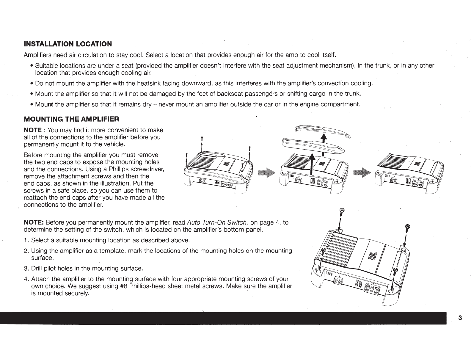
MOUNTING THE AMPLIFIER
NOTE :
You
may find it more convenient to make
all
of the connections to the amplifier before you
permanently mount it to the vehicle.
Before mounting the amplifier you must remove
the
two
end caps to expose the mounting holes
and the connections. Using a Phillips screwdriver,
remove the attachment screws and then the
end caps, as
show·n
in
the illustration. Put the
screws
in
a safe place, so you can use them to
reattach the end caps after you have made
all
the
connections to the amplifier.
NOTE: Before you permanently mount the amplifier, read Auto Turn-On Switch, on page
4,
to
determine the setting of the switch, which
is
located on the amplifier's bottom panel.
1.
Select a suitable mounting location as described above.
2.
Using the amplifier as a template, mark the locations of the mounting holes on the mounting
surface.
3.
Drill pilot holes
in
the mounting surface.
4.
Attach the amplifier to the mounting surface with four appropriate mounting screws of your
own choice.
We
suggest using #8 Phillips-head sheet metal screws. Make sure the amplifier
is
mounted securely. ·
3

4
CONNECTIONS
.IMPORTANT: Disconnect the vehicle·s negative(-) battery terminal before beginning the installation.
The
GTXSOO
amplifier
is
capable of delivering high power levels, and requires a heavy-duty
and
reliable connection to the vehicle's electrical system
to achieve optimal performance. Please adhere to the following instructions carefully.
If
you have not already done so, remove the two end caps that cover the amplifier's connectors
as
explained
in
Mounting the Amplifier, on page
3.
This will provide easier access to
all
of
the amplifier's connectors.
AUTO TURN-ON SWITCH
No remote turn-on connection
is
necessary because the
GTXSOO
includes signal-sensing turn-on, which
will turn the amplifier on when it receives an audio signal at any of its input connectors. The amplifier will
automatically turn off approximately five minutes after the input signal ceases.
If
your audio system's source unit includes a remote turn-on wire and you would prefer to use it, the
amplifier will sense that you've used a remote turn-on. wire and that connection will override the signal-
sensing turn-on. If necessary, you can defeat the signal-sensing turn-on circuit by moving the amplifier·s
Auto Turn-On switch to the "Off" position.
USING THE CONNECTORS
The
GTXSOO
uses the same type
of
screw terminals for power and
speaker connections. This type
of
termrnal
is
easy to use and allows
the easy connection of large-gauge wire.
To
use the connectors, use a Phillips screwdriver to loosen the
connector's set screw, insert the bare wire and tighten the set screw
to secure the wire
in
the connector, as shown
in
the illustration to the
right.
IM
'PORTANT: Make sure the
(+)
and (-) speaker bare wires do not
touch each other or the other terminal.at both the amplifier terminals
and speaker terminals. Touching wires can cause a short circuit that
can damage the amplifier. Loosen
Screw
Insert
Wire Tighten
Screw

GROUND (GND) CONNECTION
Connect a wire (minimum 8AWG -8.4mm2) from the
amplifier's GND terminal directly to a solid point on the
vehicle's chassis.
• For a good connection, use sandpaper to clear the
paint from the metal surface at this chassis location.
Use a star-type lock washer to secure the wire's
connection.
POWER (12V) CONNECTION
1.
Connect a wire (minimum 8AWG -8.4mm2) directly to
the battery's positive
(+)
terminal.
2.
Install a fuse holder for a 50A fuse on this wire within
18
..
(46cm) of the battery's (+)terminal. Do not
install the fuse
in
the holder
at
this time.
•
3.
Route this wire to the amplifier's location and
connect it to the amplifier's +12V terminal. Be sure
to use appropriate grommets wheneve·r routing
wires through the firewall or other sheet metal.
IMPORTANT: Failure to adequately protect the
positive wire from potential damage may result
in
a
vehicle fire.
4.
When you are finished routing and connecting this
wire, install the 50A fuse
in
the holder you installed
near the battery.
Power
Connectors
o o Remote Turn-On (optional) J
ooo
o (
)oo
...._------·.--~--·•
.
ooo
D . .
oo
,...
r::::::u::8:J
o a a a a a a a a o
~
#18 AWG (0.82mm2) Wire
'+12V
Chassis Ground
(bare metal)
1
~
#BAWG (8.4mm2) Wire
~
#BAWG
(8
..
4mm2) Wire

6
SPEAKER AND INPUT CONNECTIONS
Always connect the(+) speaker terminal on the amplifier to the(+) terminal on the speaker and
the(-)
speaker terminal on the amplifier to
the(-)
terminal
on the speaker. ·
.
IMPORTANT: Make sure the
(+)
and (-) bare wires do not touch each other or the other terminal at both the amplifier termin·als and speaker
terminals. Touching wires can cause a short circuit that can damage the amplifier.
SPEAKER CONNECTIONS
Connect the subwoofer to the amplifier's Sub
(+)
ard
(-) terminals.
~
~T
l H
I
:::r:
~
~
~ ~
SUB
25A
ZSA
+12V
0
GND
-0+
~~
[[ooo[]
~
.
~
I
FUSE
REM
Subwoofer
I I
I I
~
}~
z
~l
I s
+-~
;_
z I
Always connect the
(+)
terminal on the amplifier to the
(+)
terminal on the subwoofer and the (-) terminal on the amplifier to the (-) terminal on the
subwoofer.
-
,;"
IMPORTANT: Make sure
the
(+)
and (-) bare wires do not touch each.other or the other terminal at both the amplifier terminals and subwoofer
terminals. Touching wires can cause a short circuit that can damage the amplifier.
NOTE: Minimum speaker impedance is 2 ohms.

INPUT CONNECTIONS
Input Connectors
.
Use RCA audio cables to connect source units with preamp-level outputs to the amplifier; use the supplied.bare wire-to-RCA adapters to connect to
source units that
don't
have RCA output connectors.
Use a small Phillips screwdriver to loosen the adapter's set screws and insert the speaker wires into the holes on the,back of the adapter. Tighten
the set screws to secure the wires.
Loosen
Screw Insert
Wire Tighten
Screw
Always connect the
(+)
speaker wire to the
(+)
terminal on the adapter and the (-) speaker wire to the (-) terminal on the speaker.
· IMPORTANT: Make sure the
(+)
and (-) bare wires do not touch each other. Touching wires can cause a short circuit that can damage the source
unit or the amplifier.
When you're finished, plug the adapters into the input connectors on the amplifier.
•
You
can use either input connector to connect a source component with a single mono subwoofer output.
7

8
CONTROLS AND INDICATORS
Bass
Boost
Control
Bass
@
0
d812
pp~~~o
Power/Protect j
LED
Crossover
Frequency
Control
==-
i
45Hz
300Hz
SET THE GTX500
1
S CROSSOVER FREQUENCY CONTROL
Volume
Control
NOTE:
The GTX500's internal crossover
is
permanently set for low-pass operation._
The Crossover Frequency control limits the amount of high-frequency energy sent to the subwoofer. The setting you
use will depend on the type and location of your system's subwoofer, and on the performance of your system's full-
range speakers.
If
you used a high-pass crossover on your system's other speakers, start by setting the GTX500's
Crossover Frequency control to a frequency somewhat lower than the high-pass crossover setting you used for
the system's other speakers. After listening to music on the system for a time, fine-tune the Crossover Frequency
control setting to achieve a smooth transition from the subwoofer
to
the rest of the system's speakers while
avoiding a "hole," where the sounds that occur between the subwoofer and other speakers seem
to
drop out. The
illustration to the right shows the recommended Crossover Frequency control frequency range for subwoofers
..
Freq
®
• •
45Hz 300Hz

SET
TH
·E GTX5oo•s
VOLUME
1.
Initially set the GTX5oo·s Input Level switch to the "Hi1" position.
NOTE:
If
you have connected the GTX500 amplifier to your factory audio system's speaker outputs, the audio system may show a "speaker
disconnected" message, or may fail to play with
an
amplifier connected to its owtput.
If
this happens, set the GTX500's Input
level
switch to the
"Hi2" position. The "Hi2" position includes a circuit designed
to
fool this type of factory system into "seeing" a speaker connected
to
its output.
2.
Turn the Volume control on the GTX500 fully counter-clockwise.
3.
Play some dynamic music through your source unit and turn its volume up so the music
is
at a farily loud volume.
4.
Slowly turn the Volume control on the GTX500 clockwise until the subwoofer sounds balanced with the rest of the music.
NOTE: If you turn the GTX5oo·s volume control
all
the way up and the subwoofer still
is
not loud enough, turn the volume control down
all
the
way,
switch the GTX5oo·s Input Level switch
to
the
..
Low
..
position and repeat Step
4.
5.
Check the balance between the subwoofer and the rest
ofthe
music at higher listening levels to make sure there
is
no
audible distortion
in
the
subwoofer.
If
there
is,
turn the GTXsoo·s volume control counter-clockwise until the distortion disappears.
SET
THE
GTX500
1
S BASS BOOST
The Bass Boost control can provide up to 12dB
of
bass boost at 45Hz. Set this control according to your personal taste, but be careful not to set
the control,
at a high enough level to cause audible distortion or bottoming of your subwoofer.
PROTECT
/POWER
LED
•
LED
Illuminates green: Normal operation (power
is
on).
•
LED
is
off: Amplifier
is
in
standby mode.
•
LED
is
red
(no
sound from amplifier): Amplifier
is
in
protection mode.
See
Troubleshooting,
on page 10.
9

10
TROUBLESHOOTING
If
your amplifier isn•t performing the way you think
is
should, check to see if the problem
is
covered
in
this section before calling your dealer or
contacting JBL customer service.
PROBLEM
No sound (the amplifier·s Power LED
is
off)
No sound (the amplifier·s Power LED
is
green)
CAUSES AND SOLUTIONS
• Check that the amplifier·s +
12V and GND connections have been properly made.
• Check if the fuse on
the+
12V
wire located near the battery
is
blown:
If
so, replace it with
an
identical fuse.
• Check
all
amplifier fuses; if any are 'blown, replace them with identical fuses.
•
If
you are using the amplifier·s
REM
connection for turn-on, check that the wire
is
properly
connected to the audio system·s remote turn-on wire or to the vehicle•s ACC power terminal.
• Check that
all
amplifier input and speaker connections have been properly made.
• Check that the amplifier·s Volume control
is
not turned
all
the way down (counter-clockwise).
• Check that the vehicle audio system·s source unit's volume control
is
not turned
all
the way
down.
No sound (the amplifier·s Protection LED
is
red)
• Confirm that the vehicle·s electrical system
is
supplying between 9V and 16V
DC
to the
amplifier.
If
the supply voltage
is
outside of this range, correct the condition before attempting
to use the amplifier. ·
•
If
the amplifier has overheated, wait until it has cooled down before_attempting
to
u~e
it again.
• Disconnect
all
speakers from the amplifier and attempt to turn it on again:
-
If
the amplifier turns on (the Power
LED
is
orange), there
is
a short circuit
in
one or more of
the speaker wires.
Correct
all
short circuits before reconnecting the speakers to the amplifier.
-
If
the amplifier does not turn on (the Protection LED
is
still red and the Power
LED
is
off),
contact your authorized JBL dealer for assistance.

PROBLEM
Subwoofer
is
too quiet, even with the vehicle
audio system·s source unit volume
all
the way
up.
Sound
in
the subwoofer
is
distorted
SPECIFICATIONS
Max power {15.5V, 50Hz, 10%
THO,
2 ohms)
Rated power output
Signal-to-noise
Frequency response
Input sensitivity/impedance (low-level input)
Input sensitivity/impedance (speaker-level input)
Fuse replacement
Dimensions
(H
x W x
D)
Weight
CAUSES AND SOLUTIONS
• Check that the GTX5oo·s Volume control
is
not turned too low. See
Set
The
GTXsoo·s
Volume,
on page
9,
for more information.
• While listening to bass-heavy music, turn the Bass Boost control
all
the way down (counter-
clockwise), and then gradually increase it until the distortion begins to return. Reduce the Bass
Boost control setting slightly to eliminate the distortion and leave it set there.
• Check that the distortion is not originating from the vehicle audio system·s source unit.
GTX500
770W
X
1
350W RMS x 1 @ 4 ohms, 14.4V
DC,
<1
.0%
THO
500W RMS x 1 @ 2 ohms, 14.4V
DC,
<1
.0%
THO
>80dB
ref.
1W
20Hz-
200Hz (±0.5dB);
1OHz-
300Hz (±3dB)
1
OOmV
-2V
I>
7k ohms
2V-
15V/120 ohms
25A X 2
2-9/16
11
X
9-11/16
11
X
8-3/8
11
(66mm x 246mm x 213mm)
6.4 lb (2.9kg)
11

HARMAN International Industries, Incorporated
8500 Balboa Boulevard, Northridge, CA 91329 USA
© 2014 HARMAN International Industries, Incorporated. All rights reserved.
JBL
is a trademark of HARMAN International Industries, Incorporated, registered
in
the United States and/or other countries.
All Rights Reserved. Features, specifications and appearance are subject
to
change without notice.
Part No. 080-3238
Rev:
A
bvHARMAN
www.jbl.com
Other manuals for GTX500
1
Table of contents
Other JBL Amplifier manuals