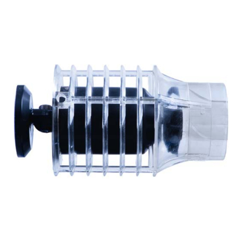
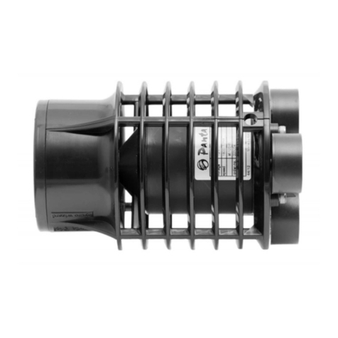
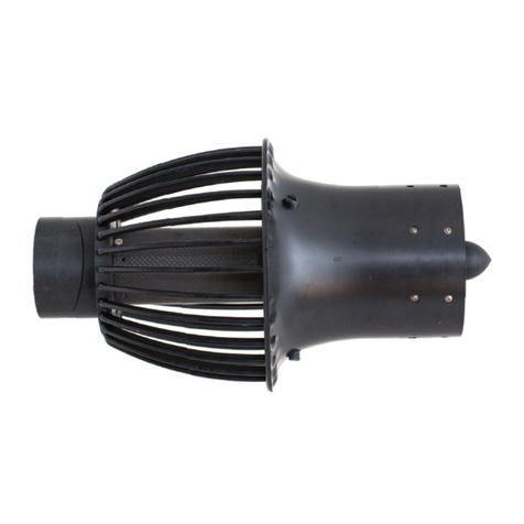
Panta Rhei hydro wizard ECM75 User manual

hydro wizard® ECM75
User Manual

3
Operating Instructions
hydro wizard® ECM75
Contents
Operating Instructions .................................................................................... 3
Safety ............................................................................................................. 5
General Safety ............................................................................................ 5
Safety hints for handling magnets: .................................................................. 6
Application ..................................................................................................... 7
General Description ........................................................................................ 8
Function ..................................................................................................... 9
Start Up ........................................................................................................ 10
Checklist before Start Up .......................................................................... 10
Positioning the pump ................................................................................ 10
Usage Instructions ........................................................................................ 13
Hardware .................................................................................................. 13
Installation and removal ........................................................................ 14
Controller Instructions (Firmware 3.0.x) ................................................... 15
Controlling the hydro wizard© ................................................................. 15
The Information Screen ........................................................................ 15
The Menu Screen .................................................................................. 17
The „make changes“ screen .................................................................. 18
Menu structure ...................................................................................... 19
Operation .............................................................................................. 21
Flow mode ............................................................................................ 21
Wave mode ........................................................................................... 22
Connecting to the Panta Rhei BUS ........................................................ 24
Cleaning function ................................................................................. 29
The Pause / Feed timer .......................................................................... 29
Unit Settings ......................................................................................... 29
Cleaning and Maintenance ............................................................................ 31
General Cleaning ...................................................................................... 31
Troubleshooting ........................................................................................... 32
Disposal and Enviroment .............................................................................. 32
Installation examples .................................................................................... 34
Technical Data ............................................................................................. 35
Performance Graph .................................................................................. 35
Motor technical data: ................................................................................ 35
Dimensions ............................................................................................... 36
Mount dimensions .................................................................................... 36
Dimensions Powerbox: ............................................................................. 37
Service ......................................................................................................... 38
Warranty for hydro wizard© products .......................................................... 39
Extent of warranty .................................................................................... 39
Warranty period ........................................................................................ 39
Warranty exclusions ................................................................................. 39

4
For your safety, please read this document before using this product
for the first time. Keep these operation instructions so you can have
access to this information at all times.

5
When used in any aquariums and ponds this device
should be plugged into a GFI socket with no more than
30mA power. If persons are in the aquarium or pond the
pump must be turned off.
Safety
General Safety
Read before using this product!
The pump should be plugged into a GFI socket with 100-240V ~
50/60Hz; fuse of 10A.
Use pump in closed rooms for aquarium applications!
The controller must not be submerged in water.
If the cables are visibly damaged the pump must not be
used. Do not attempt to repair the cables yourself.
The pump must not be lifted, carried or attached by the cable.
The motor must only be used when submerged. Running the
pump dry will damage the bearings. Guarantee and liability are
void if damage is due to the pump running dry.
This device is not meant to be used by persons (including
children) with limited physical, sensory, or mental capacities or
insufficient experience and/or insufficient knowledge. Unless
they are supervised by a person responsible for their safety and
are instructed how this device is to be used.
The user is responsible for complying with local safety laws.
The user is liable for damage to third persons caused by this
product.
This pump has been designed exclusively to move salt and
freshwater. Usage in corrosive, flammable or explosive liquids is
not permitted. The temperature of the water should not be above
35C (95F).
The operating temperature of this pump is between 5C and 35 C
(41-95F).
Do not operate damaged, incomplete, or modified (without
consent of the manufacturer) pumps. Ask an electrician to verify
that all electric safety measures have been followed.
Please read the section on care and maintenance in this
manual. All other measures, including the opening of the pump,
power supply or controller are not permitted. Always contact the
manufacturer if repairs are required.

6
Prevention of electric shock:
The plug should be freely accessible after the pump is
operating
Before starting a new pump please have an expert check
that:
grounding, fuses and interrupters are operational
according to the requirements of local energy provider
all electric connections are protected from water
Do not remove the plug by pulling on the cable. Protect
the cable from heat, oil and sharp corners. Do not kink the
cable.
Protect the cable and all electric sockets from humidity. Ensure
that the cable and electrical connections are safe from flooding
and water spills.
When servicing the pump always unplug it from the socket.
The maximum depth is 10m (32,8ft).
Safety hints for handling magnets:
(only for HW variants with magnet mount)
The magnets included in this box are many times more powerful
that conventional household magnets.
Do not bring these magnets close to devices that are sensitive
to magnetic fields, as they may permanently damage them (i.e.
credit cards, bank cards, computers...). A safety margin of 75cm
(30”) should be allowed at all times.
These Nd-magnets, at this time the strongest available magnets,
are strong enough to damage your fingers or other extremities.
Never get your hands between the magnets or the magnets and
other iron surfaces.
Keep the magnets away from heart pacemakers!
Other magnetic objects in the vicinity (i.e. knives) can be moved
uncontrollably.
Never bring the mounting magnets into direct contact with the
magnets at the base of the pump. Their attraction is so powerful
that it is impossible to prevent them coming together. Always
store the hydro wizard pump and the magnet mount separately.

7
Application
The hydro wizard is used to generate laminar flows in aquariums,
ponds or other bodies of water. The energy efficient movement of
water is a basic function. This eliminates dead zones in the water. With
the controller it is possible to generate wave simulations, in which both
wave height and length can be adjusted. The pump can simulate rivers,
tides, surge and waves. Adding oxygen or CO2 can be controlled
efficiently. The hydro wizard© is designed for use in fresh- and
saltwater.

8
1
2
3
4
5
General Description
hydro wizard©
1. Base
2. Motor
3. Nozzle + Basket
4. Impeller
5. Stator
Powerbox
1. Touchpad Display
2. Power connector
3. Connector for the Panta Rhei BUS
4. Connector hydro wizard®
5. Attachment points
1
3
2
4
5

9
Function
The movement of the impeller generates an area of low pressure,
which pulls the water from the back through the basket and pushes it
out the front over the fins of the stator.

10
Start Up
Checklist before Start Up
- Is the pump plugged into a GFI socket?
- Are all cables intact, not kinked?
- Is the stator installed? (The stator also protects hands from
getting injured by the impeller. Never use the pump without the
stator)
- Are there any objects inside the pump that can block the
impeller?
- Are there any people inside the aquarium?
Positioning the pump
- Pay attention to the safety instructions on page 5 and 6.
- Do not use single bars as grip. Always hold the motor with both
hands when carrying.
- Make sure that the pump is unplugged before placing it in the
aquarium.
- Please attach the pump only by the attachment points designed
for this purpose.
Use only the four M5 threaded holes
for mounting.
Please see page 36 for the required
measurements for installation.

11
- The cable may not be wound in operating mode
- The hydro wizard generates very high axial forces. In addition to
this, the inertia of the moving water will generate further forces
acting on the mount. If you decide to build your own mount
make sure that the attachment of the pump can handle forces of
150N.
- The pump must be fully submerged in water. It must be installed
deep enough to ensure it will not draw air from the surface.
Remember that in Wave mode the water level will change.
- The pump can be installed directly above the bottom. With a fine
substrate the pump can draw in sand. To avoid this, increase
the distance from the pump to the bottom. Particles sucked in
and pushed out the front can cause damage.
- Make sure plants or other objects do not cover the intake basket
when they get sucked onto it.
- Protect the cable from animals that could damage it.

12
- Unrelated to the ambient temperature or the performance of
the hydro wizard® pump, the power supply will get very warm.
To allow the heat exchangers on the outside of the power supply
to be most effective, the power supply should be mounted
upright. This will allow rising warm air to better carry heat away
from the device.
- Connect the plug of the motor (right) and the power cable (left)
to the power supply.
- Begin with a very low flow, and carefully watch the effects of the
laminar flow in your aquarium (are plants sucked in, decoration
knocked over?). If needed reposition the pump or reduce the
output power
-
Choosing the wrong wavelength (resonance) in any
aquarium can cause severe damage and even break the tank.

13
Usage Instructions
Hardware
The foot of the pump can be rotated through 360°
To rotate the pump into
any position loosen the
hex screw inside the
foot with a 10mm Allan
key
After the foot has been
rotated to the desired
position gently tighten
the hex screw
Do not tighten the screw, in order to avoid damaging it.

14
Installation and removal
During installation and removal always pull the plug
- Loosen the screws on the tube
(7 pcs) (Torx10 screwdriver)
- Locked torque max. 80Ncm
- Pull the stator forward
- Remove centre bolts (3 pcs)
- Make sure that the impeller sits in the
centre of the casing by screwing the large
bolts. The fins of the impeller must not
touch the casing. Try to keep an equal
distance between the tip of the impeller
and the wall of the casing. Turn the
impeller by hand to check the distance in
all points.
Do not overtighten the bolts, in order to prevent the tube from
being deformed. If necessary, you may have to loosen an
opposing bolt slightly so that you can screw the other side in a
little more.
If you loosen the M5x20 bolts
(4 pcs) below the adjustable foot, the
motor separates from the basket. You
can then withdraw the motor
forwards out of the basket.

15
Controller Instructions
(Firmware 3.0.x)
Controlling the hydro wizard©
The controller can be programmed with your finger, or a non abrasive
touch screen pen. All touch surfaces can be easily reached with your
finger. When activating a field it will be displayed with a black
background. When the finger is removed it will be confirmed.
Figure 1: Touch screen surface confirmation
The following will explain the most important fields of the touch screen.
Warning: for maintenance ALWAYS disconnect the hydro wizard
from the power grid. Do not use any of the following stop functions
to perform maintenance on the hydro wizard!
The Information Screen
The information screen displays information about the flow status of the
pump. The upper part of the screen displays the flow mode. The center
part of the screen will display the most important data about the flow
mode.
Figure 2: Information screen
Display active
mode / stop
Display: flow
setting and
performance
time Stop hydro wizard®
go to Main Menu

16
The Stop field on the screen will stop the Hydro Wizard. The display will
blink when stopped. Pushing this field again will restart the hydro wizard
®
.
When shipped the hydro wizard will arrive in Stop mode after it has
been plugged in.
The MENU field will call up the main Menu.
The center of the screen will allow you to quickly access the settings in
the mode that has been selected.
Figure 3: quick access to the settings
quick access to flow
mode

17
The Menu Screen
The menu screen is used to change and display the settings of the
hydro wizard.
Figure 4: menu screen
The upper portion of the screen displays the flow menu. The center
portion shows the available submenus. The middle one of the
submenus has been selected. To select a different submenu use the
arrows at the bottom of the screen. The arrow at the right enters that
submenu, the arrow button on the left returns to the menu above. To
confirm this selection this item will get bigger to make them more
visible.
Figure 5:
confirmed return button
The INFO button returns back to the info screen. The STOP button will
stop the hydro wizard.
Display: active menu
change to submenu
stop hydro wizard®
go to upper menu item
go to lower menu item
go to info menu
go back to
previous menu
Selected menu item
(in the middle)
other menu items are
available but not
displayed
change to menu above
(selected)

18
The „make changes“ screen
This screen is used to make changes to most of the settings.
Figure 6: make changes screen
The left center field displays the flow value. Above and below are
buttons to increase or decrease the number by the smallest step
possible.
On the right side is a field that can be used like wheel, it is used to
increase or decrease the value smoothly with no steps. The ok field in
the center of the wheel is used to exit the make changes to settings
screen.
decrease number
„settings wheel“
exit (ok)
increase number
number display

19
Menu structure
Figure 7: menu structur
Figure 8: settings in flow mode
Flow
Settings
Mode
Info
Quick access
Duration
Start
Manuel
Automatic
Language
Date
Time
Turn
Tool Tip
Active
Password
Main menu
Settings
Pause
Cleaning
Unit
Password
Depens on mode
Restart
Reset
Network
Dimming
Duration

20
Picture 9: settings in wave mode, enter time
Figure 10: settings in profil mode
Current A
Settings
Current B
Time A
Time B
Time B-A
Find frequency
Time A-B
Phase delay
New interval
Settings
Interval 1
Interval 3
Interval ...
View
Change
Delete
Table of contents
Other Panta Rhei Water Pump manuals
Popular Water Pump manuals by other brands

KSB
KSB RDLO Series operating instructions

Wilfley
Wilfley DRYLOCK II A7 RETROFIT Installation, Operation, Maintenance and Storage Manual

JABSCO
JABSCO 30580 Series manual

Bogert Aviation
Bogert Aviation 19M-30X Product instructions

Grundfos
Grundfos CR Installation and operating instructions

EBARA
EBARA ESA300W instruction manual

GORMAN-RUPP PUMPS
GORMAN-RUPP PUMPS VS6A60-B Installation, operation, and maintenance manual with parts list

Flowserve
Flowserve PVML 25.04.04 User instructions

Agilent Technologies
Agilent Technologies DS202 1Ph instruction manual

Brave
Brave MBRP750DP3 owner's manual

SprayTECH
SprayTECH EPX2155 owner's manual

Grundfos
Grundfos CRN-H MAGdrive Installation and operating instructions