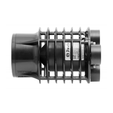
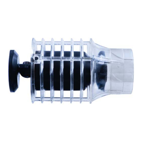
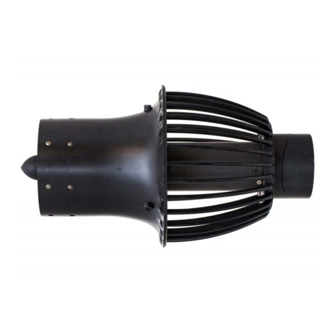
Panta Rhei Hydro Wizard ECM 75 User manual

Hydro Wizard®ECM 75
Operating manual

Version: 430221b
As of: 09.12.2019
Panta Rhei GmbH
Managing Director: Matthias Kählig
Langen Hop 5
30900 Wedemark - Brelingen
Telephone +49 (0) 5130-60 957 27
Fax +49 (0) 5130-60 957 26
Panta Rhei Galerie
Langen Hop 5
30900 Wedemark - Brelingen
MAIL: [email protected]
WEB: www.panta-rhei.shop
Natural
Aquarium
Technology
PAN
T
ARHEI

Hydro Wizard®
ECM 75


Operating manual
Hydro Wizard®ECM 75
Content
01) Scope of delivery .............................................7
02) Safety guidelines .............................................7
a) General safety guidelines....................................... 7
b) Protection against electric shock ........................9
03) Intended use and scope of application . 10
04) General description........................................11
a) Functional description.............................................11
05) Commissioning...............................................12
a) Checks before commissioning.............................12
b) Installation of the pump ........................................13
06) Usage instructions hardware.................... 16
07) Controlling instructions ............................. 18
a) Controlling the Hydro Wizard®.................................................... 18
b) The information screen......................................... 19
c) The menu screen.................................................... 20
d) The „make changes“ screen.................................21
e) Menu structure.........................................................22
f) Operation...................................................................24
08) Cleaning function .........................................33
09) The pause / feed timer................................34
10) Unit settings ...................................................35
11) Cleaning and maintenance ....................... 37
a) General Cleaning.....................................................37
12) Assembly and disassembly.......................38
13) Troubleshooting........................................... 40

7
Operating manual Hydro Wizard®ECM 75
14)
Disposal and environmental protection
...41
15) Warranty provisions.....................................42
a) Extent of warranty .................................................43
b) Warranty period ......................................................43
c) Warranty exclusions ..............................................43
16) Technical data.............................................. 44
a) Pump characteristic curve .................................. 44
b) Pump technical data............................................. 44
c) Dimensions............................................................... 46
d) Mount dimensions ................................................. 46
17) Optional accessories...................................47
18) Spare parts .....................................................47
Thank you very much for choosing this product! The
Hydro Wizard®ensures the exact simulation of na-
tural movements in the aquaculture and in aquaria.
What is special about the Hydro Wizard®compared
to other products is that a laminar fl ow – and not a
turbulent fl ow – is produced by the Hydro Wizard®.
A turbulent fl ow is not good for the fi sh. As a result
of the exact calculation of all components in the fl ow
simulation, the Hydro Wizard®is unrivalled until today
within the area of effi ciency and the environmentally
friendly scope of services.
Before the fi rst commissioning, please read this ope-
rating manual carefully – for your own safety, the sa-
fety of others and your animals. Store this manual in
a safe place, so that you can access the information
at any time.

Operating manual
Hydro Wizard®ECM 75
7
01) Scope of delivery
• Hydro Wizard®ECM 75 (1 piece)
• Powerbox (1 piece)
• Touchscreen pen (1 piece)
• Power cord (1 piece)
• Operating manual (1 piece)
02) Safety guidelines
a)General safety guidelines
Only connect the device in aquaria, garden ponds and in
their protection zones to an electrical outlet with residual
current device (earth leakage circuit breaker) with a rated
current of not more than 30 mA an (DIN VDE 0100). If you
have any questions concerning this, please contact an elec-
trically skilled person. If persons are in the tanks or ponds,
the pump must not be operated.
Before installation and commissioning, please ob-
serve the following instructions:
• The electrical connection is made to a safety
socket outlet with a mains voltage of 100-240
V~ 50/60 Hz; fuse at least 10 A.
• Only use in closed rooms for aquarist applica-
tions!
• The powerbox must not come into contact with
water.
• In case of visible damage to the cables, the
drive must not be operated. Do not attempt to
repair the cable yourself.
• Do not use the cable for carrying or pulling the
drive. The cable must not be used for mounting
the drive.
• The pump must only be operated underwater.
Dry running will destroy the bearings. In the
event of non-compliance, warranty and liability
claims will expire.
!
!
!

Operating manual Hydro Wizard®ECM 75
8 9
• This device is not intended to be used by per-
sons (including children) with reduced physi-
cal, sensory or mental capabilities or a lack of
experience and/or knowledge – unless these
persons are supervised by a person responsib-
le for their safety or they receive instructions by
this person on how to use the device.
• The operator is responsible for the compliance
of local safety regulations.
• Within the working area, the user is liable to
third parties for damages caused by the use of
the device.
• The pump is exclusively suitable for pumping
seawater and freshwater. Pumping corrosive,
fl ammable or explosive liquids is not permitted.
The temperature of the pumped liquid must not
exceed 35 °C (95 °F).
• The working temperature of the device is bet-
ween 5 °C and 35 °C (41 - 95 °F).
• Do not work with a device that is damaged, in-
complete or modifi ed (without the permission
of the manufacturer). Before commissioning,
ensure by an expert that the required electrical
protective measures are available.
• Please read the instructions in the opera-
ting manual concerning the topic “Cleaning
and maintenance”. All measures beyond this,
opening the pump and the switchboards in par-
ticular, are not permitted. Always contact the
manufacturer in the event of repair.
!

Operating manual
Hydro Wizard®ECM 75
8 9
b)Protection against electric shock
After setting up the pump, the mains plug must be fre-
ely accessible at any time during the operation.
Before commissioning your new pump, have an expert
checked whether the
- grounding, protective multiple earthing and resi-
dual current-operated protective circuit work pro-
perly following the latest safety regulations
- electrical plug connections are kept dry
• Do not use the cables to remove the plug from
the socket. Protect the cables against heat, oil
and sharp edges. Do not bend the cables.
• Protect the cable and the electrical connections
against humidity. Make sure that the cable and
the electrical connections are in an area that
cannot be fl ooded.
• When working on the device, remove the mains
plug from the socket.
• The minimum immersion depth depends on the
set pumping capacity.
• The maximum operating depth is limited by the
cable length.
!
!

Operating manual Hydro Wizard®ECM 75
10 11
03) Intended use and scope of application
The Hydro Wizard®is used to generate laminar
fl ows in aquaria, ponds and similar waters. Ener-
gy-effi cient circulating of water is a basic function in
this connection. „Dead zones“ can thus be avoided.
With the controller (or the optional USB interface) it
is possible to generate wave simulations, in which
both, wave height and lenght, can be adjusted. The-
reby, wave height and wave length can be adjusted.
This is used to simulate courses of rivers, tides and
breakers. The Hydro Wizard®is designed for use in
freshwater and seawater.

Operating manual
Hydro Wizard®ECM 75
10 11
04)General description
Hydro Wizard®
Powerbox
a)Functional description
By rotation of the impeller, an area of low pressure
is generated which sucks in the medium from be-
hind through the fi ns of the basket and – past the
fl ow conditioner – ejects it again at the front.
4
3
2
1
5
1. Flexible mount
2. Motor
3. Nozzle + Basket
4. Impeller
5. Flow conditioner
1. Touchpad display
2. Power connector
3. Connector for the
Panta Rhei CAN-Bus
4. Connector Hydro
Wizard®
5. Attachment points
1
2
34
5

Operating manual Hydro Wizard®ECM 75
12 13
05)Commissioning
a)Checks before commissioning
• Is there a ground fault circuit interrupter connec-
ted upstream of the device?
• Are all cables free from damage? Cables must
neither be bend nor rolled up!
• Is the fl ow conditioner installed? The fl ow con-
ditioner also protects fi ngers from getting inju-
red by the impeller. Never use the pump wi-
thout without fi nger protection!
• Are there any objects in the drive that may
block the impeller?
• Before starting your Hydro Wizard®please
make sure, that there are no people inside the
tank!
• Make sure that the mains plug was disconnec-
ted before installing the drive in the tank!
• Pay attention to the safety instructions on pa-
ges 7 to 9.
• Do not use single bars as grip. Always hold the
pump with both hands when carrying.

Operating manual
Hydro Wizard®ECM 75
12 13
b)Installation of the pump
1. Installation step:
• Please attach the pump only by the attachment
points designed for this purpose.
Use only the four M5
threaded holes for
mounting. The dimen-
sions can be found in
the dimension draw-
ing on page 45.
Important notes:
• The cable may not be
wound in operating mode.
• Appropriate mounting material can be purcha-
sed directly from Panta Rhei. Information on
this can be found on page 46 of this operating
manual. The dimensions can be found in the
dimension drawing on page 45. The Hydro Wi-
zard®itself generates very high axial forces.
In addition, there are the inertia forces of the
moving water masses in the tank. If you do not
use Panta Rhei equipment for mounting, plea-
se pay attention that the support, on which the
Hydro Wizard®is assembled, can safely ab-
sorb a force of approx. 150 N.
• During operation, the pump must be comple-
tely immersed into water. The drive should be
assembled in such a depth below the water
surface that no air is sucked in from the surfa-
ce during operation. Please pay attention that
the height of the water level is changing during
wave simulation.

Operating manual Hydro Wizard®ECM 75
14 15
• The drive can be directly assembled via a solid
ground in the tank. In case of a sandy ground,
a vacuum eff ect may be the result. In order to
avoid that, increase the distance to the ground.
Objects sucked in may emerge from the fl ow
conditioner at high speed and cause damage.
• It must be ensured that the intake basket is not
covered by plants and similar objects.
• The cable must be protected against animals
which are able to damage the cable.
2. Installation step:
• Unrelated to the ambient temperature or the
performance of the Hy-
dro Wizard®, the power-
box will get very warm.
To allow the heat exch-
angers on the outside
of the powerbox to be
most eff ective, the po-
wer supply should be
mounted upright. This
will allow rising warm
air to better carry heat
away from the device.
3. Installation step:
• Connect the plug of the pump (right) and the
power supply (left) with the powerbox and sub-
sequently with a socket.

Operating manual
Hydro Wizard®ECM 75
14 15
Important notes:
• When switching on for the fi rst time, the speed
of the drive should be increased slowly and,
while doing so, observing the fl ow eff ects in the
tank. Is something sucked in or are decorative
items or plants blown away? If this is the case,
choose a diff erent location of the pump or re-
duce the performance
• Choosing the wrong wave length (resonance)
in any aquarium can cause severe damage
and even break the tank. Further information
see page 25.
!

Operating manual Hydro Wizard®ECM 75
16 17
06)Usage instructions hardware
The foot of the pump can be rotated through 360°.
To rotate the pump into any position loosen the hex
screw inside the foot with a 10mm Allan key.
After the foot has been ro-
tated to the desired posi-
tion gently tighten the hex
screw.
Do not tighten the screw, in
order to avoid damaging it.

Operating manual
Hydro Wizard®ECM 75
16 17

Operating manual Hydro Wizard®ECM 75
18 19
07) Controlling instructions
a)Controlling the Hydro Wizard®
The controller can be programmed with your fi nger, or
a non abrasive touch screen pen. All touch surfaces
can be easily reached with your fi nger. When activa-
ting a fi eld it will be displayed with a black background.
When the fi nger is removed it will be confi rmed.
Figure 1: Touch screen surface confi rmation
The following will explain the most important fi elds of
the touch screen.
Caution: For maintenance ALWAYS disconnect the Hydro
Wizard®from the power grid.
Do not use any of the following stop functions to perform
maintenance on the Hydro Wizard®!
!

Operating manual
Hydro Wizard®ECM 75
18 19
b)The information screen
The information screen displays information about
the fl ow status of the Hydro Wizard®.
The upper part of the screen displays the fl ow mode.
The center part of the screen will display the most
important data about the fl ow mode.
Figure 2: Information screen in fl ow mode
When shipped the Hydro Wizard®will arrive in STOP mode
after it has been plugged in.
The STOP fi eld on the screen will stop the Hydro Wi-
zard®. The display will blink when stopped. Pushing
this fi eld again will restart the Hydro Wizard®.
The MENU fi eld will call up the main menu.
The center of the screen will allow you to quickly ac-
cess the settings in the mode that has been selected.
Figure 3: quick access to the settings
Display active
mode / stop
Display: flow
setting and perfor-
mance
actual time
Stop the
Hydro Wizard®
Go to main menu
i

Operating manual Hydro Wizard®ECM 75
20 21
c)The menu screen
The menu screen is used to change and display the
settings of the Hydro Wizard®.
Figure 4: menu screen
The upper portion of the screen displays the fl ow
menu. The center portion shows the available sub-
menus. The middle one of the submenus has been
selected. To select a diff erent submenu use the ar-
rows at the bottom of the screen. The arrow at the
right enters that submenu, the arrow button on the left
returns to the menu above. To confi rm this selection
this item will get bigger to make them more visible.
Figure 5: confi rmed return button
The INFO button returns back to the info screen. The
STOP button will stop the Hydro Wizard®.
Display: active menu change to submenu
go back to
previous menu
Stop the
Hydro Wizard®
go to info
menu
go to lower menu item
Selected menu item
(in the center)
go to upper menu item
other menu items
are available but not
displayed
change to menu above
(selected)
Table of contents
Other Panta Rhei Water Pump manuals
Popular Water Pump manuals by other brands

Enerpac
Enerpac WU Series instruction sheet

OSIP
OSIP ZM 50 instructions

Grundfos
Grundfos DME series Installation and operating instructions

KNF
KNF Laboport N820 Operating instruction

MYERS
MYERS ME45MC -11 Series Installation and operation manual

Stancor
Stancor SSD Series Installation, operation and maintenance manual