Pantong LTS-48 User manual

USER MANUAL
TELEPHONE TEST SET
DATA SAFE

Page
1
1. GENERAL
The Handset Portable Test Telephone employs technology in integrated circuit
design to provide both DTMF (Touch Tone) and dial pulse output for both
a).Public telephone network of voice service, and b). ADSL network for voice on
data service with DSL safe capability. The Handset also provides last number
redial, 10 speed dial, flash, mute, high impedance monitoring, and electronic
ringer, with field replaceable test leads and belt clips. This Portable Test
Telephone, often called a “butt -in” is a self-contained line–powered, portable
handset used by installers, repair technicians, and other authorized personnel for
line testing and temporary communications.
2. DESCRIPTION
Physical Characteristics (Figure 1):
The case (A) is designed to give rugged service and withstand the rough handling
normally associated with craft tools.
The keypad (B) has 15 buttons conductive rubber that is recessed into the receiver end
of the housing. The recessed bezel provides physical protection to the keypad and prevents
accidental button operation.
The spring – loaded belt clip (C) located on the bottom of the housing, ensures a
secure connection to a belt top or D – ring. The belt clip may be replaced in the field.
The Portable Test Telephone is equipped with test leads (D) may be replaced in the
field.
The Hanging loop (E) located on top of case for any purposes of hanging up handset
Figure 1.
A
D
C
E
B
The safety condition is not to connect Test Set to public
electrical power lines ( 220/110 VAC )

Page
2
3. SPECIFICATIONS:
General Spec
Loop Resistance 2.2 K Ωat 48 VDC (20 mA loop current)
Talk Mode Resistance 200Ωtypical at 20 mA
Monitor Mode Resistance 120 KΩat 1 KHz
Pulse Dial Output Rate 10 PPS
Percent Break 58 – 66 mS
Interdigit interval 740 – 820 mS
DTMF Output
Frequency
Key Input Freq.Output (Hz)
Row 1 697
2 770
3 852
4 941
Col 1 1209
2 1336
3 1477
Tone Output 194 mv(-12dBm )
Distortion to Tone level -20dB
Frequency error +1%
Level per Tone Pair - 8 dBm min
High versus Low Tone difference 4dB max
Level variation +5 dB
Physical
Case Rugged and Withstand Nylon 6/6
Keypad 15 conductive rubber buttons
Belt loop connect Spring – loaded belt clip
Test leads Tinsel wire PVC insulated with Nylon braided Jacket
1.5 meter long terminated by Bed-of-nail and Spike
alligator clips
Dimension
Length 22 cm
width 6 cm
Height 8.5 cm
Weight 0.3 Kg
Environmental
Temperature Operate - 5 to + 50 C
Storage -40 to + 70 C
Humidity 90%
Shock test drop 7 meters

Page
3
4. CONTROLS AND INDICATORS
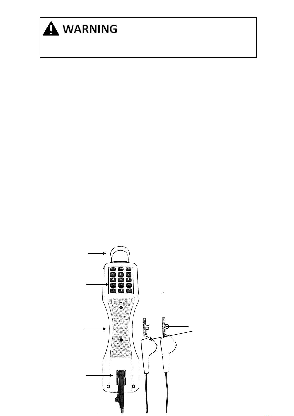
4.1 Handgrip controls ( Figure 2 ):
TALK/RING/MONITOR Switch. This three-position slide switch is located under
the handgrip just above microphone. The switch is labeled as MONITOR for high
impedance monitoring, RING for ringer , and TALK for off-hook
In the MONITOR position, the Handset is a high impedance coupling to the
telephone line. This allows for telephone line monitoring without current drawing
from the lines so not making any interrupt to conversation on telephone lines.
In the RING position is on-hook with electronic ringer for in-coming call alert. On
this position If unit touch to AC lines ringer will alarm with continuously ringing
sound which user should disconnect handset from the lines immediately and
carefully
In the TALK position, the Handset is off-hook and may be used for dialing and
talking. In this mode, the Handset performs as an ordinary telephone.
All positions will not disrupt to data service on xDSL and High speed network
PULSE/TONE Switch. This two-position slide switch, labelled PULSE/TONE, is
located under the handgrip just below the receiver. The switch selects the
signalling output : TONE for DTMF or PULSE for dial pulse.
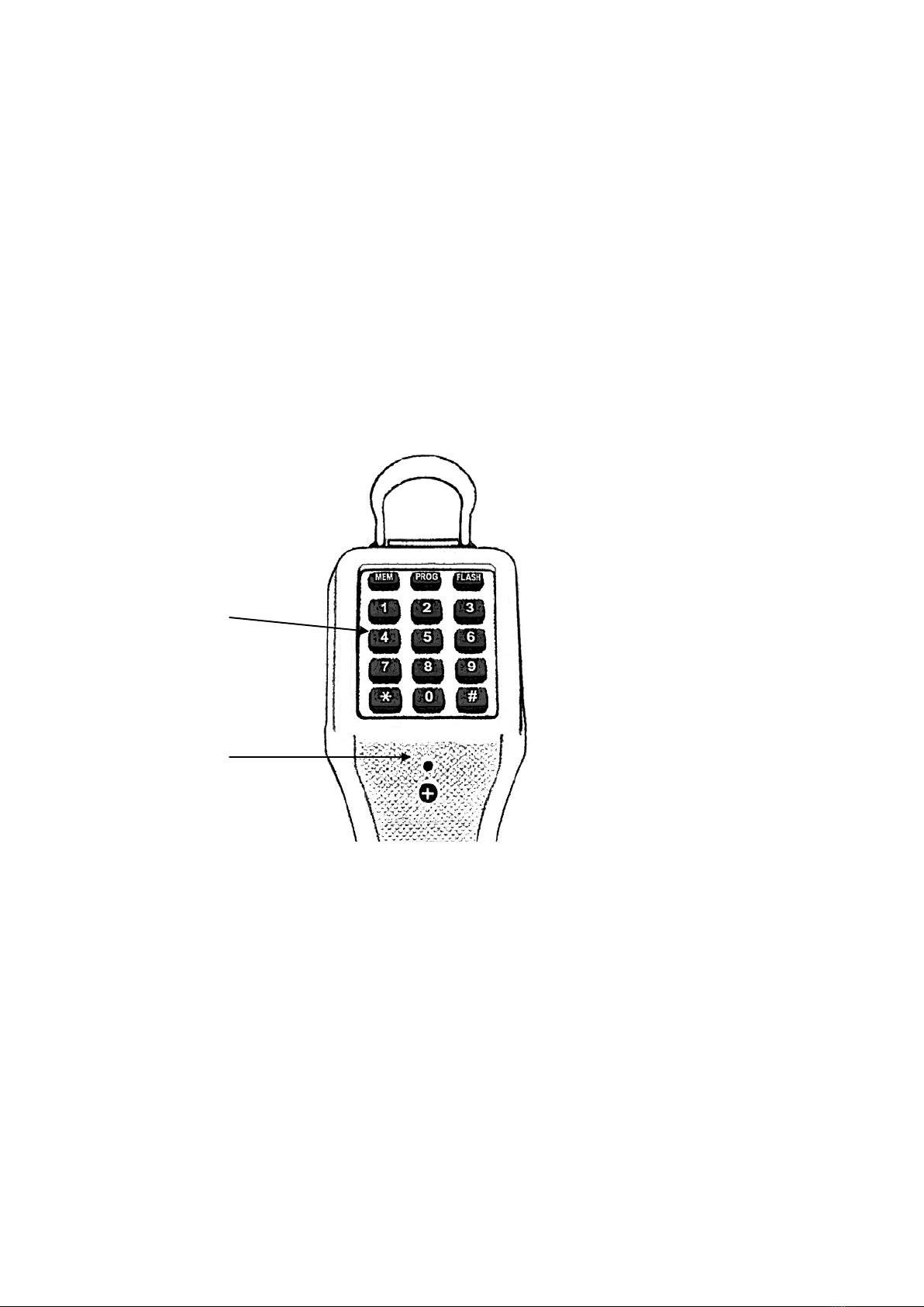
4.2 Keypad Controls and indicator (Figure 3) :
Keys The 12 standard keys will send either DTMF Tones or Pulses, depending
on the PULSE/TONE switch setting.And also 3 functional keys
Last Number Redial Button. “R” serves as a last number dialled key
(Figure 2). The number may be redialled in either pulse or tone mode, as selected
by the PULSE/TONE switch
Polarity LED This red LED is Located just below the keypad. The LED indicates
line polarity. The LED will not light if the red test lead is connected to the Ring
(negative) side of the line and the black test lead is connected to the Tip( positive)
side of the line. The red LED with light if the test leads are reversed : that is, with
the red test lead connected to the Tip (positive) side and with the black test lead
connected to the Ring (negative) side.
5. OPERATION
5.1. Monitoring. by move the TALK/RING/MONITOR switch to the MONITOR
position then connect the test lead clips to the line under test for audio monitoring
in high impedance. This will not disrupt voice and data service to the line.
“Optional monitoring in medium impedance be done by moving switch to RING
position for a higher sound level receiving”.

Page
4
5.2 Dialling ( select signalling to be dialed by PULSE/TONE switch, often set to TONE)
•Move the TALK/RING/MONITOR switch to the MONITOR position then
connect the lead clips to the telephone line. Listen to receiver (ear piece) to
verify that the line is idle ( silent)
•Move the TALK/RING/MONITOR switch to the RING position and if AC
present on the lines, ringer will alarm with continuous ringing, user should
disconnect lead clips from the line immediately and carefully.Avoid touching
any metal parts and short test clips to each other.
•Move the TALK/RING/MONITOR switch to TALK position and verify if
dial tone is received. Key the calling number to the keypad. If tone signalling
being selected. The responsible frequency tones of each digit will be
generated for each button pressing.
•End the dialling by moving back the TALK/RING/MONITOR switch to
the MONITOR position (recommended when stanby or store the test set).
•Press FLASH button to on and off-hook if need to dial again.
Note:Operating on xDSL and data lines will not disrupt service on network
during and after dialing
5.3 Polarity Check. Move the TALK/RING/MONITOR switch to MONITOR then
connect the lead clips to the line under testing. Move the same switch from
MONITOR to TALK with instruction described in 5.2 above. The red LED will not
light if the red lead clip is connected to the ring (negative) side of the line and the
black lead clip is connected to the tip (positive) side of the line. The red LED will
light if the lead clips are reversed that is, with the red lead clip connected to the tip
(positive) side and the black lead clip connected to the ring (negative) side.
5.4 Programing and Making a Speed dialing. ( repertory memory)
Program number, connect handset to the lines then off-hook by slide bottom
switch to TALK then 1) press PROG 2) press MEM 3) press digit 0 - 9 for
memory location 4) enter telephone number which can include * # or FLASH
5) press PROG
Speed dialing, off-hook then 1) press MEM 2) press digit 0 - 9 for memory
location
Figure 2
PULSE/TONE SWITCH
TALK/RING/MONITOR
SWITCH
Last Number Redial
TONE
PULSE
TALK
RING
MONI -
TOR

Page
5
5.5 MUTE. Is toggle button located together with PROG button and use to
cancel microphone to transmitting voice, By this microphone off user can also
have clearer sound on receiver when operate in the noisy area.
5.6Last Number Redial ( repertory memory) The last number dialled can be
automatically redialled with the PULSE/TONE switch set to either PULSE or
TONE.
Use the following procedure for a number up to 18 digits long
•Go on-hook (move the TALK/RING/MONITOR switch to the RING
position) for at least 1/2 second.
•Move the TALK/RING/MONITOR switch back to the TALK position
•Press the “R” button and the number will be automatically redialled
5.7 Electronic Ringer (ON/OFF). Move the TALK/RING/MONITOR switch to RING
position and connect test leads to the telephone line. The piezo-electric
transducer electronic ringer will “ring” whenever it detects ringing voltage on the
lines.Answer the call by moving the TALK/RING/MONITOR switch to TALK.
6. CONNECTION
Handset comes with test leads which one end terminated by RJ11 for
connecting to Handset. Handset designed with RJ11 jack on the bottom for
connection with either test leads or telephone lines with RJ11 jack. The other
end of test lead terminated by bed-of-nail and spike alligator clipsfor
connection to telephone lines.
7. WARRANTY
We guarantee our equipment and workmanship for a period of 1 year after
purchase. The warranty with not cover for product that was defected by
accident, improper uses and one repaired by other than manufacturer’s
personnels.
Figure 3.
Keypad
Polarity LED
Table of contents