Parabel CR-505 User manual

LAN Adapter with Bypass Port
СR-505
User Manual
Version 1.0
06.09.2016
Novosibirsk 2016


Developer and producer: LLC Parabel
Russia, 630090, Novosibirsk-90, p/b 126
http://www.parabel.ru
Email: [email protected]
Phone/fax: +7-383-2138707

Attention! The device cannot be used with communication lines having
no lightning proofness and running outside the limits of one building

Content
1.INTRODUCTION...........................................................................................................................................6
2. ADAPTER STRUCTURE ..............................................................................................................................7
3. CONNECTING ADAPTER PANEL .............................................................................................................. 8
4. DEVICE CONFIGURATION ........................................................................................................................9
4.1. Mode Selection ................................................................................................................................................... 9
4.2. Watchdog Controller Clearing ........................................................................................................................... 11
4.3. Application Example.......................................................................................................................................... 12
5. SCOPE OF SUPPLY....................................................................................................................................14

1.INTRODUCTION
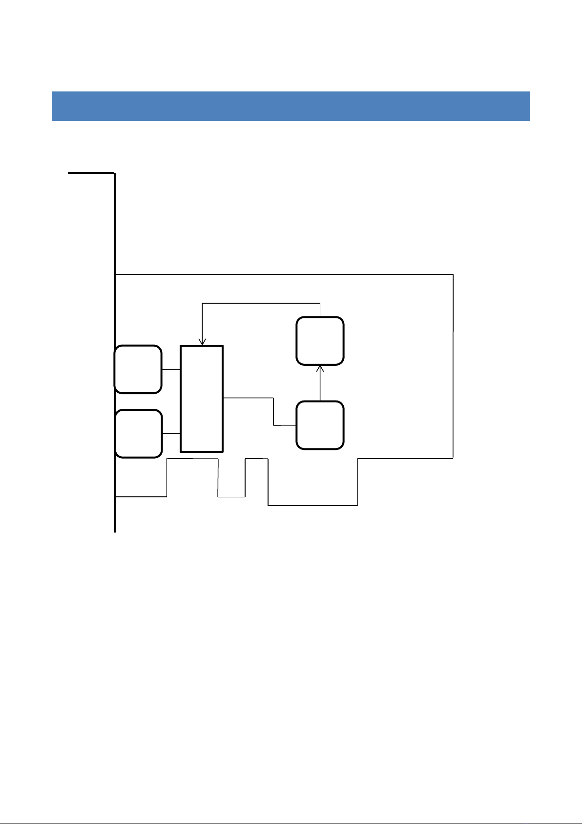
LAN adapter CR-505 is a single channel Ethernet adapter with one main port and one bypass
port. Switching from the main port to the bypass port (bypass mode) is automated when the server
power supply is off or watchdog controller reacts. Bypass port serves to connect a standby server.
Adapter CR-505 can be used for “hot”backup servers –Web-servers, data base and terminal ones.
The adapter has the following characteristics:
•Form factor –PC card PCI-express
•Standard or low-profile board
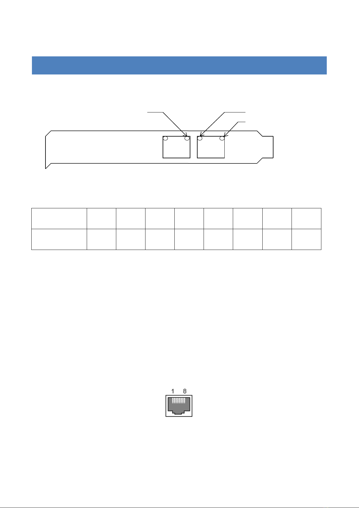
•1 main port 10/100/1000 Base-T, 1 bypass port
•Guaranteed length up to 50 m
•Full/Half duplex with flow control support IEEE 802.3x
•Supporting jumbo frames of 9216 bytes
•Polarity and entangled pairs self-correction
•Microsoft NDIS5 checksum offload (IP,TCP,UDP)
•Supporting IEEE 802.1Q VLAN
•Watchdog controller 60 or 600 seconds

2. ADAPTER STRUCTURE
The adapter structure is shown in the picture.
The device is based on MAC controller RTL8111, which port GBe is connected to the relay
module. Depending on the mode, the relay module connects either the bypass port (port1) or the
MAC controller to the main port (port 0). The relay module is operated with the help of the
watchdog controller.
Port 1
Port 0
RTL8111
MAC controller
Relay module
Watchdog
controller

3. CONNECTING ADAPTER BOARD
Below you can find the front panel of adapter CR-505 and a port connection table.
Outputs
1
2
3
4
5
6
7
8
Destinations
A+
A-
B+
C+
C-
B-
D+
D-
Notes.
1. A,B,C,D –duplex twisted-pair wires
2. Standard 10/100 uses pair A for transmission and pair B for receipt
3. LINK/ACT LED –signal presence and packet transmission/receipt indicator
4. Tx led - packet transmission indicator
5. Bypass led –bypass mode indicator (port1 connected to port0).
Used connection type RJ-45
PORT 0
PORT 1
Link/Act led
Tx led
Bypass led

4. DEVICE CONFIGURATION
4.1. MODE SELECTION
The mode is selected with the help of jumpers on board (see the picture).
The mode dependence on jumpers position is shown in the table below. On –the jumper is closed,
Off –the jumper is open, X –the position is ignored.
JP1
JP1
JP2
JP3
JP4
JP4
JP5

JP5
JP4
JP3
JP2
JP1
Mode
On
X
X
X
X
Bypass mode is on only if there is no power supply
of the server. The jumper is precedent over the
others.
Off
X
X
X
On
Watchdog controller clearing happens when any
packet is transmitted (by Tx led signaling).
Off
X
X
On
X
Watchdog controller clearing happens when a
record is made to MAC controller register.
Off
X
On
X
X
Watchdog controller timeout is 60 sec
Off
X
Off
X
X
Watchdog controller timeout is 600 sec
Jumper/Condition
No Power
Hardware
Reset of
Server
Watchdog
controller
timeout
Clearing
watchdog
controller
JP5=On, JP1=X, JP2=X
B
W
W
W
JP5=Off,
JP1=On or JP2=On
B
W
B
W
Notes.
1. JP4 is not used.
2. B = bypass mode, port 0 is connected to port1
3. W –working mode, port 0 is connected to the MAC controller

4.2. WATCHDOG CONTROLLER CLEARING
According to the taken work model, the watchdog controller shall be cleared with the server
software from time to time. This condition is a sign of the stable functioning of the software.
Receiving periodically a clearing signal the watchdog controller views the software operation as
normal and finds no need to switch the ports to the bypass mode. Depending on the adapter
configuration, the clearing signal can be made by two means.
Clearing by outcoming packets
It is the simplest way to control the work of the server. On having a packet from the adapter to be
transmitted the watchdog controller gets cleared and begins counting the period again. If after the
expiration of tx period the packet is absent, the software is believed to have failed and the ports are
switched to the bypass mode. The advantages of the way include the simplicity of the utilization:
no need to install any extra software on the server. The disadvantages are also clear: this means is
too brutal and it does not allow controlling a failure of a certain application, for example.
Clearing by making records to the adapter register
Watchdog controller is cleared with setpci utility (pciutils packet).
# setpci -v -d 10ec:8168 4a.b=0
This command resets the watchdog controller and the adapter keeps working. The advantage of this
method is that the server performance condition verification can be as complex as you wish. The
server administration can check external connections with the script as well as the performance of
certain applications. On having a positive response the script shall clear the watchdog controller.

4.3. APPLICATION EXAMPLE
According to this scheme the primary server checks from time to time the connectivity to the
standby server via LAN adapters #1 and #2. Adapter CR-505 is installed to the primary server and
is connected to the standby server with a bypass port. If the connectivity is lost (or the software of

the primary server “hungs”) the standby server is connected to the operating network via bypass
port. The standby server shall also have the exact copy of the primary server software; also, the
same MAC address shall be set for adapter #3 and adapter CR-505. The given scheme provides for
a “hot”backing up of the primary server. The administrator can be notified of the occurred server
rotation by the appearance of an Ethernet link in adapter #3.

5. SCOPE OF DELIVERY
•Adapter board
•CD with user’s manual
•Certificate of warranty
•Packing box sized 26x17x3 cm
The set weight is not over 0.5 kg.


Table of contents
Popular Adapter manuals by other brands

Polar Electro
Polar Electro Adapter and Bridge Driver IrDA USB 1.1 user manual

DH Instruments
DH Instruments PK-MOL-4VCR-14SWG installation instructions

Pilz
Pilz Conv USB/RS 485 operating instructions

Dynex
Dynex DX-AC1200 Quick setup guide

Quatech
Quatech SSP-200 user manual

StarTech.com
StarTech.com ICUSBAUDIO instruction manual