Paramount Pools Poolquip Lido User manual

LIDO
INGROUND OR
INDECK POOLS
OVAL POOL
INSTRUCTION
MANUAL

LIDO POOL
A few important safety hints
Enjoy Your Swimming Safely!

LIDO POOL
16,200 litres
22,295 litres
27,300 litres
33,150 litres
36,000 litres
43,225 litres
54,000 litres
4. Fence Pool Area (even if it is temporary approved site fencing).
5. Mark out pool location.
6. Prepare site.
7. Set out the final pool dimensions.
8. Assemble frames for pools.
9. Assemble pool ladder.
10. Deepen or dish Pool centre if required.
11. Install walls – First decide on filter location.
12. Cut wall for plumbing returns.
13. Prepare cove and spread sand on base.
14. Install ground cover and bolt strip.
15. Install liner.
16. Check and secure liner.
17. Fit vertical supports.
18. Fit top rails, vertical and seats.
19. Fit plumbing for filter.

LIDO POOL
Check with your local Council. A building
permit may be required or it may be
necessary to meet local body regulations.
The Fire Department may also require
notification.
The table to the left shows how to select your pool parts. Follow the line on
which your pool size is shown. The numbers indicate the number of pieces
per component.
WHEN ORDERING SPARE
PARTS PLEASE STATE
DESCRIPTION & PART NO.
slim
for wall bolts
3
2
5
3
6
7
9
10
10a
24
25
24
25 26
15
6
14
14
17
20
16
21
22
19
19
21
13
13
14
15
16
17
18
19
20
21
22
23
24
25
Lido Part No. Details
PART1549
PART1574
PART1432
PART1551
PART1557
PART1404a/1405a
PART1406a
PART1312
LINR varies
PART1301-5
PART1431
PART1554
PART1313
PART1314-6
PART1555
PART1556
PART1559
PART1558
PART1579
PART1580
PART1579
PART1581
PART1571
PART1314
PART1315
PART1316
GCOV1707-11
Screw Only
8
5a

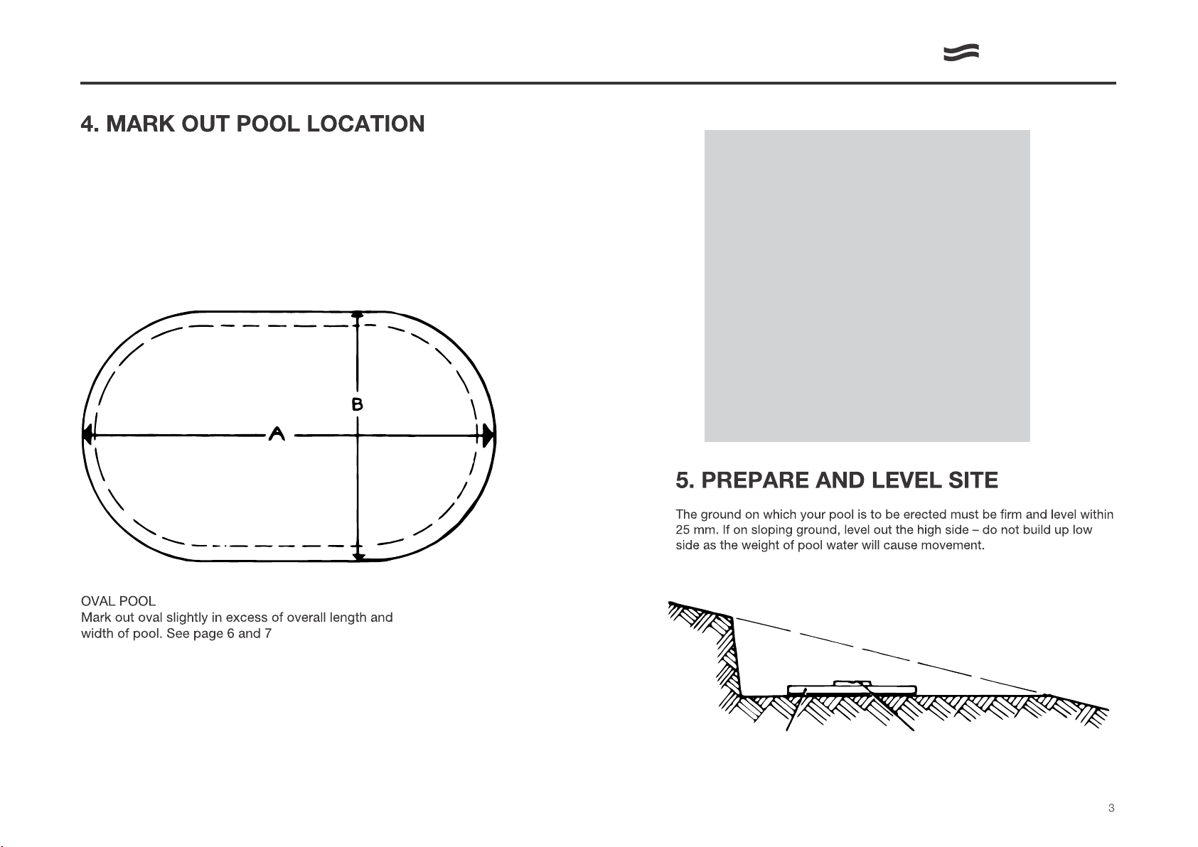
DO NOT FILL LOW SIDE OF EXCAVATION
Natural surface
Excavated leveled surface
Straight edge Carpenters level
LIDO POOL
LINEAL MEASUREMENTS
(FOR TILING AND DECKING)
1612 – No.1 Wall x 1 = 14.254mtrs
2012 – No.2 Wall x 1 = 16.621mtrs
2412 – No.3 Wall x 1 = 18.989mtrs
2315 – No.3 Wall x 1 = 18.989mtrs
2715 – No.3a Wall x 1 = 21.356mtrs
3015 – No.4 Wall x 1 = 23.723mtrs
3815 – No.1 Wall x 2 = 28.508mtrs
1548 – No.1 Wall x1 = 14.254mtrs
1748 – No.2 Wall x 1 = 16.621mtrs
2048 – No.3 Wall x 1 = 18.989mtrs
When positioning the pool, ensure that its location
meets all Council By-Laws.
IN PLANNING THE LOCATION OF YOUR POOL, KEEP WATER
SAFETY IN MIND. APPROVED SITE SAFETY FENCING MUST BE
ERECTED AROUND THE WORKSITE.

2420mm
1612
A
B
(To end of Base Channel)
Pressure plate
Base channels
must be
parallel
(INSIDE WALL)
2012 2715
BB
AA
LIDO POOL
Note: Side braces extend 600mm out from the pool wall.
SET OUT FINAL DIMENSIONS FOR POOL FRAME
Once the site is satisfactorily levelled, accurately re-mark the final position of the pools
as per the dimensions on the ground plan. The final pool marking should come within the
previously levelled area.

2412 2315
LIDO POOL
Note: Side braces extend 600mm out from the pool wall.
SET OUT FINAL DIMENSIONS FOR POOL FRAME
Once the site is satisfactorily levelled, accurately re-mark the final position of the pools
as per the dimensions on the ground plan. The final pool marking should come within the
previously levelled area.

APEX OF CURVE
A
(INSIDE WALL)
2261mm RADIUS
19mm
591mm 1181mm 1181mm 1181mm 591mm 19mm
Pressure plate
4724mm
PEG No.1 PEG No.2 B
1603mm
3206mm (To end of base channel)
2261mm
RADIUS
APEX OF CURVE
A
RADIUS
2261mm
3206mm (To end of base channel)
1603mm
PEG No.1
19mm 591mm 1181mm 1181mm 1181mm 1181mm 1181mm
7087mm
PEG No.2
591mm
19mm
2261mm RADIUS
(INSIDE WALL)
600mm
B
Pressure
plate
LIDO POOL
Note: Side braces extend 600mm out from the pool wall.
SET OUT FINAL DIMENSIONS FOR POOL FRAME

DRAINAGE
FILTER
DO NOT BACK FILL LOW
SIDE OF EXCAVATION
Excavated leveled surface
Natural surface
Straight edge Carpenters level
LIDO POOL
2. Caution: Do not erect your pool on
gravel, asphalt, tar paper or any oil
based materials.
It is essential that all traces of hardy
weeds be completely removed from
under the pool as the may puncture
the liner. Vegetation such as nut grass
or onion weed must be treated with
an effective weed killer before
cleaning the site. Be sure your pool
area is free from stones, sticks, wire,
roots and other sharp objects.
Concrete is acceptable provided a
bed of builders ‘sand is used under liner.’

LIDO POOL
ASSEMBLE FRAMES FOR POOLS

WASHER FITTED BOTH SIDES
CHECK VERTICALS WITH CARPENTERS LEVEL
CROSS- CHECK LEVELS
SAND
STAKES TO POSITION
BOTTOM RAILS
CHECK LEVEL
ASSEMBLY OF LOWER RAILS & CONNECTOR
610
9
4
6
LIDO POOL
7A. PRELIMINARY FRAME EXCAVATION
17. Remove frame assembly.

18. Excavation trenches for the base
channel 76mm wide x 76mm deep.
20. After excavations are complete,
assemble the pressure plates to the
pool frame constructions. Using the 4
self tapping screws (3) attach the
pressure plate (17) to the base
channels (16). Using the bolt 24
connect pressure plates together.
Tighten with washer (26) and
nuts (25).
21. Position frames into excavated holes. 23. Check whether all uprights are level,
in line, and level with each other.
22. Install to measurements shown on
ground plan. Pressure plates must be
resting on ground level.
24. Check decks horizontally (trim excavation
to suit). Use a level and piece of timber.
25. Use a line level to check levels across
pool to opposite frames.
LIDO POOL
19. Excavate the holes for the skid
members 457mm x 457mm x 457mm
for concrete.

CHECK VERTICALS WITH CARPENTERS LEVEL
CROSS CHECK LEVEL
STAKES TO
POSITION
BOTTOM RAILS
CHECK LEVEL
HARD
BOARD
475mm
475mm
475mm
GENERAL VIEW
27. Check opposite corner to corner
measurements.
29. Note: It is Imperative that there is a
solid concrete square behind skid member.
30. If the plates are installed on soft fill
the weight of water can make the
vertical shift out of level. If in doubt
pack a small batch of concrete under
plate. (17)
28. Your pool is now ready to concrete.
Check vertical levels before concrete
hardens and pour concrete into
excavated hole to ground level.
31. Place the required amount of Sand
inside the pool.
LIDO POOL
26. Check corner to corner measurements
as per ground plan. The measurement
should be the same to have the frames
square.

7B. SIDEWALL ASSEMBLY
32. and 33. Note: During assembly take
special care when handling the sidewall.
Careless handling may result in a
buckled wall, when erecting. Assembly
on very windy days should be avoided.
If a colourband wall is being installed,
select colour preference and unroll
accordingly.
Locate Centre Point Between Pressure
Plates.
Centre Point is 1603mm from pressure plate.
34. Locate peg positions 1 and 2 as
shown in ground plan.
35. Tie a marker (screw driver) to one end
of string line and from each peg scribe the
required end radius measurement. This will
be a guide for laying the base rail.
37. Slide the end rails into the connectors
leaving approximately 32mm gap between them,
and position with stakes so the rails conform to
the radii marked out previously.
38. Check the distance to the apex of the
curve from pegs 1 and 2 making sure
the apex is in line with the 2 pegs
(see ground plan).
LIDO POOL
36. Select and install bottom rails for
between side supports; these rails have
a larger radii than the end rails.
2012 = 2 rails, 2315 = 2 rails
2412 = 4 rails, 2715 = 4 rails
3015 = 6 rails, 3815 = 10 rails

IMPORTANT!
The pool structure and any
conductive materials,
including but not limited to,
stainless steel ladders and
aluminum fencing within
1.25mtrs of the pool edge
are required to be
equipotentially bonded by
a registered electrician in
accordance with
AS/NZS 3000:2018
MIN 800mm MAX 400mm
Maximum
Gradient
2:1
1
2
LIDO POOL
8. ASSEMBLE LADDER
9. DEEPEN POOL CENTRE
Safety ladder designed for a pool installed in an
above ground situation.
Stainless steel ladder specially
designed for your inground pool.
You must provide an access ladder to and from pool during pool installation. Do not climb on unsupported walls.

39. The Paramount pool wall is supplied with
a pre-stamped, cut out section, sized for
the paramount Sp1500 Surface Skimmer.
It is positioned 600mm from the outside
end of the coiled wall. Before installing the
wall into the rails, ensure wall is correct
way up and you are starting in the desired
place.
40. Use 2 pieces of hardboard, or similar,
about 61cm square. One to stand the
coiled wall on, the other to move it onto
as you progress.
42. A few rails (6) may be placed on top of
the wall to give rigidity whilst uncoiling.
On reaching the end of the roll the bolt
holes may not line up. This alignment is
achieved by moving the rails in or out to suit.
44. Cover the bolt heads with plastic
cover strip (11).
45. Tape it firmly into place starting from
the bottom. Cut off 25mm from the top.
43. When the holes do line up, loosely
assemble all the bolts, nuts and washers.
Note: It is important to fit a washer to
each side of the wall and have a bolt
head inside the pool. Firmly tighten all nuts.
Although the pool wall is supplied with the
surface skimmer section pre-punched, the
eyeball holes are not cut.
This is to allow you to custom fit the eyeball
returns (2) in the most suitable position.
NOTE - It Is essential that the cutting of
the wall for these eyeballs is completed at
this stage of the pool wall Installation, so
all metal filings and off-cuts etc, cannot
damage the pool liner.
Procedure - Position the eyeballs where
required,
- Oval pools; position both eyeball r~turns
at the opposite end to the surface skimmer
- Round pools; position the eyeball returns
approximately 120° and 240°, around from
the surface skimmer.
It is recommended to fit the eyeballs at a
distance of 200 to 300mm down from the
top rail.
Cut a 48mm diameter hole for each eyeball
with suitable small side-cutters (Tin Snips)
or similar remove all metal burrs and sharp
edges with a round file, check hole sizing
with actual eyeball before continuing.
DO NOT INSTALL SURFACE SKIMMER OR
EYEBALLS AT THIS STAGE.
This is completed at Step 18.
LIDO POOL
10. INSTALL WALLS 11. CUT WALL FOR THE
PLUMBING OF THE
EYEBALL RETURNS
41. The join should be hidden behind
a vertical support (10) page 9, start
uncoiling the wall with the end directly
over a connector thus covering join
by a vertical. It is advisable to have
someone hold the end of the wall to
prevent creeping along the rail.

46. Before spreading sand over floor unscrew
pressure plates and fill base channel and
pressure plate areas with sand to prevent
any movement.
Re-install pressure plates
Note: It is very important that this step is
completed correctly. The sand has to be
packed tightly to eliminate movement of
pressure plate when walked upon.
48. Spread the sand over the entire floor area
to an even depth of approximately 50mm
making sure you have 50mm of sand over
the pressure plate.
49. Compact the sand on the floor by
tramping or rolling until a footprint no
longer shows.
50. Installation of liner
Remove all seats and connector plates.
51. Place the pool pad (GROUND COVER)
over the entire floor area and hold it in
position by taping in to the pool wall.
53. Position the liner so that wall-floor
seam is an equal distance from pool
wall at both ends and sides. The liner
has several seams running across the
pool floor, which must be straight and
parallel to side frames.
52. Unroll the liner in the center of the pool
with the smooth weld up. (The liner is
easier to install if left unrolled in the sun
to warm and soften) .
54. Pull the liner wall up over the pool wall
and hold in place with plastic coping strips. (7)
Note: Remove footwear before walking
on liner.
LIDO POOL
12. PREPARE COVE
AND SPREAD
SAND ON BASE
13. INSTALL GROUND
COVER
14. INSTALL LINER 15. CHECK & SECURE
LINER
47. Build up an even cove of firm sand or
earth around the wall of the pool
approximately 150mm and pack firmly.

55. Commence running water into pool.
When you have approximately 25mm,
remove all floor creases by working
from the center to the wall. Remember
the more water over 25mm depth, the
more difficult it is to remove the creases.
VERTICAL
RAIL
JOINER
6
4
10
6
Do not install these items until the water level has
filled to just below the cut out positions in the
wall.
This will ensure the liner is cut with accuracy and
lines up easily to the metal cut-outs. reducing the
chances of unsightly wrinkles around these fittings.
Procedure - Paramount SP1500
Surface Skimmer
Hold the face plate in position through the cut
out, pierce the liner through the 15 bolt holes (1)
with a pointed spike to allow easy insertion d the
bolts.
Place one gasket on the inside of the face plate
and carefully insert bolts through. starting with
the four comers.
Place 2nd gasket (2) on outside of the wall and
then position actual skimmer box on the
protruding bolts. Ensure both gaskets have
seated properly, fit nuts to bolts and tighten
all 15 evenly.
Finally trim the liner around Inside of the
skimmer mouth, check skimmer basket is
locked and position deck lid.
EYEBALLS
Cut the liner to the hole size in the wall. Ensure
you cut it the same size or slightly smaller, but
not larger.
Fit a gasket to the eyeball, then position eyeball
through the liner, then wall. Thread lock nut on
and tighten.
Proceed with the connecting of the plumbing.
Do not cover pipes until you have run water
through the entire filtration system, checking all
joins for leaks.
Wall
Liner
LIDO POOL
DO NOT DRAIN THE POOL.
Leave the pool filled throughout
the year, suitably protected
by a winterizing programme.
Unless the liner has been
damaged and cannot be
repaired on site, draining the
pool unnecessarily could result
in excess liner shrinkage which
is not covered under warranty.
If the liner has been damaged
repairs should be carried out
preferably with the liner in place
and removed only if replacement
is necessary. If a liner is to be
returned under warranty, please
contact your local store prior to
shipment. Returned liners must
be thoroughly cleaned and dried
inside and out. Mark the damaged
area with a black grease pencil.
The liner should be folded neatly
and packed securely into a
cardboard box marked with return
name and address. The pool can be
drained by using the vacuum and
diverting the return line, or by
siphoning.
Replacement Parts: Replacement
parts can be ordered from your
local store. Include the pool size,
part name and number when
ordering.
16. FIT VERTICAL
SUPPORT
17. FIT TOP RAILS/SEATS
18. FIT SURFACE SKIMMER
AND EYEBALL RETURNS
MAINTENANCE
Use vaseline on inside to slide connector to assist
assembly.
This manual suits for next models
7
Table of contents
Popular Swimming Pool manuals by other brands

GRE
GRE EVO 790094 instruction manual

Bestway
Bestway Power Steel Series owner's manual

Steinbach
Steinbach Styriapool oval 012345 instruction manual

Intex
Intex Easy Set owner's manual

Outside Living Industries
Outside Living Industries ubbink 7524820 Note of assembly

Steinbach
Steinbach SPEED-UP 010015 manual