Park Audio II V4-900 MkIII User manual

PROFESSIONAL POWER AMPLIFIERS
V-series
V4-900 V4-1200 V4-1800
V4-2400 V2-2400
MkIII MkIII MkIII
MkIII M kIII
OWNER’S MANUAL
PARK AUDIO II

ACCESSORIES
1. Power Cord 1 ea.
2. Owner’s Manual 1 ea.
3. Warranty 1 ea. Printed in Ukraine

32
TABLE OF CONTENTS
Page
General........................................................................................................... 3
Unpacking....................................................................................................... 3
Design Features............................................................................................. 4
FunctionalFeatures........................................................................................ 4
Block Diagram................................................................................................ 8
Front Panel ..................................................................................................... 11
Rear Panel...................................................................................................... 12
Input Module with Sensitivity Switch ........................................................... 13
Input Module with Crossover ....................................................................... 14
Cabel Requirements ..................................................................................... 15
Inputand Output Connectors ......................................................................... 16
Rack-Mounting Requirements....................................................................... 17
AC Power Requirements ............................................................................... 17
Operating Modes ........................................................................................... 18
LinkingUp ....................................................................................................... 21
Troubleshooting.............................................................................................. 27
Specifications ................................................................................................. 28
Operating Conditions.................................................................................... 30
Dimensions .................................................................................................... 31

2 31
AVIS
RISQUE DE CHOC ELECTRIQUE
NE PAS OUVRIR
CAUTION! The amplifier runson 230V AC voltage. Removing the cover willexpose you
toapotentiallydangerousvoltage!Do notusetheunitiftheelectricalpowercordisfrayed
orbroken.
Power is supplied from 230V AC single-phasegrounded 50/60 Hz source.
CAUTION! The amplifier can yield dangerous output voltage! Do not touch the
non-insulated cable parts connected to outputs of the unit in operation!
CAUTION! The amplifier yields high output power. The manufacturer shall not be held
responsible for any damage to the speakers caused by excessive power from the unit.
CAUTION! Thehighsound pressurecausedbythehighoutput signalappliedtospeaker
systems, may endanger your hearing. Please, take care to observe the required safety
precautions.
DIMENSIONS
445 max
40
3
7
4
4
1
4
482
466
7
6
8
8
9
6

30 3
GENERAL
The V4-900 MkIII, V4-1200 MkIII, V4-1800 MkIII, V2-2400 MkIII, V4-2400 MkIII
power amplifiers (V - Series) are designed for sound signal high-fidelity amplifica-
tion within professional sound reproduction systems.
Toensurefaultlessoperationoftheunit,please,taketimetoreadthismanualbefore
use.
ATTENTION!
The V4-900 MkIII, V4-1200 MkIII, V4-1800 MkIII, V2-2400 MkIII, V4-2400MkIII
amplifiers have the same design and functional features and differ only in the
schematics elements, output power and weight. Unless specified otherwise, the
word “amplifier”hereinafter applies to any of the above models.
UNPACKING
The manufacturer’s quality control system provides for careful examination of each
product before it leaves the factory to ensure its flawless appearance. After unpacking,
please, check the unit for anyphysicaldamage.In case of damage, please,contact your
localdealer. Keep the shipping carton and allpacking material, as you mayrequire them
for re-shipment of the unit.
OPERATING CONDITIONS
Air temperature: 5 ... 35°C
Atmospheric pressure: 86.6 ... 106.7kPa (650 –800 MMHG)
Relative humidity: less than 80%

4 29
DESIGN FEATURES
Physical Design
The amplifier is enclosed in a metal (steel) case of 2U height. The amplifier is designed
to be installed into a standard 19" rack.
The amplifier incorporates:
–power supply source;
–two similar amplifying monoblock units;
–input module;
–indication and input level control unit.
The input module is replaceable.
Power Supply Source
Common for both channels. The power supply source consists of a soft-start unit, a
toroidal transformer, ac/dc converters and a filter capacitor PCB.
Cooling System
Fans are used to cool the output stage. The cooling system is independent for each
channel. The air flows backwards. The cooling intensity changes progressively in the
process of operation. On power-on and when the output power is fairly low, the fan runs at
a low speed thus minimizing the acoustic noise. As the output power goes up and so rises
the temperature of the output stage heat sinks, the fan starts blowing harder, thus
intensifying the cooling process.
Output Stage
The output stage is designed with the use of complementary pairs of TOSHIBA bipolar
transistors. The output stage is based on Class H technology with double-level power
supply.
FUNCTIONAL FEATURES
Output Short-Circuit Protection
The amplifier is provided with individual protection for each channel and global
protection in the bridge mode. The protective system does not switch the amplifier off, so it
resumes its unattended operation after the short-circuiting conditions are gone.
Overload Protection
The double-stage overload protection system provides both reliable output stage
protection and perfect sonic quality even under overload.
In case of a short-time overload lasting up to 3 msec., (e.g. overload caused by a
sudden drop of total load impedance), only the output stage current protection goes active
limiting the current running through the output transistors at the safe level. In this case the
protection system does not preclude the amplifier from delivering, for a short while, a full
output power (without any output voltage reduction) even to loads of very low impedance.
In case of a more continuous overload, the protection system activates the built-in
Clip-limiter, which reduces the level of the input signal and eliminates the distortion, caused
by hard clipping.
DC Output Protection
The amplifier schematics precludes any clicks or noise occurring during the power-
on/off transition processes without utilizing any relay commonly used for connecting the
Frequency Response: 20 Hz ... 20 kHz (0.2dB, Pnom.)
10 Hz ... 60 kHz (1dB, 1W)
Total Harmonic Distortion: 0.003% (1kHz)
0.02 % (20Hz... 20kHz)
Slew Rate: 40 V/µs (channel), 80 V/µs (bridge)
Damping Factor:
–V4-900MkIII, V4-1200MkIII 400 (1kHz, 8Ohm)
–V4-1800 MkIII 400 (1kHz, 8Ohm)
–V2-2400 MkIII, V4-2400 MkIII 600 (1kHz, 8Ohm)
Channel Separation: 60dB (1kHz)
Signal-to-Noise Ratio: 100dB (unweighted)
Input Impedance: 10 kOhm (balanced)
Sensitivity: 0.775V (standart model)
0.775V, 1.4V, 32dB ( * )
High-pass
Filter Cutoff Frequency**: 35Hz
High-Pass Filter Slope Rate**: 24dB/octave
Crossover Frequency***: 125 Hz
Power Requirements: ~230 V AC, 50/60 Hz
Weight:
–V4-900 MkIII 14kg
–V4-1200 MkIII 15kg
–V4-1800 MkIII 16kg
–V2-2400 MkIII 18.5kg
–V4-2400 MkIII 18.5kg
Dimensions:
–width 482 mm
–height 96 mm
–height in rack 2U
–depth 414 mm
–depth in rack 374mm
* Only when an input module with a sensitivity switch is installed.
** Only when an input module with a sensitivity switch or with a crossover is installed.
*** Only when an input module with a crossover is installed.

28 5
output signal to a speaker system. To prevent any DC damage to speaker systems, the
amplifier incorporates the triak protection system for each channel, which short-circuits the
amplifier output in case of DC voltage or powerful LF fluctuations.
High Frequency Energy Protection
In case of any powerful high frequency fluctuations caused by bad contact in the input
cable connectors or those transmitted to the amplifier input from any other device (e.g.
crossover, mixing console, etc.), the protection system enables the built-in clip-limiter, which
reduces the level of the input signal. This protection system serves to prevent any damage
to tweeters as might be caused by non-musical signals of powerful high frequency spectrum.
Thermal Protection
The thermal protection is to preclude any overheating of the output stage.
The amplifier incorporates a double-step thermal protection system which precludes
overheating of the output stage of the amplifier without suspending its operation and
disabling the input signal (and output signal, accordingly).
The thermal protection system is coordinated with the cooling system and in the
following way.
When the output power is fairly low, the fan runs at a low speed. As the output power
goes up and so rises the temperature of the output transistors, the fans gradually gain
speed.
Whenever the output stage temperature reaches 85°Ñ, the thermal protection system
disables the upper voltage of the output stage, thus significantly reducing the output power
of the respective channel. This status is indicated by a slightly (half-) lit ALARM LED. The
adequate sound quality in this case is provided by the built-in optoelectronic Clip-limiter
which reduces the input signal level, should any distortion occur.
If overheating of the output stage persists and its temperature rises to 95°Ñ(as a rule,
this is the case only when the cooling fan has broken down), the thermal protection system
inhibits the input signal as well as the output stage of the respective channel. This status is
indicated by a brightly (full-) lit ALARM LED. The amplifier automatically resumes its
operation, in the reverse order, after the output stage transistors have cooled down.
Soft Start
The soft start system is provided to reduce inrush current to the amplifier and to
minimize the noise contributed by the amplifier to the power mains during the power-on
process.
Soft Signal Start
During the power-on process, this feature ensures smooth gain from zero to the
maximum level to provide for a smooth rise of the sound level emitted from the loudspeakers.
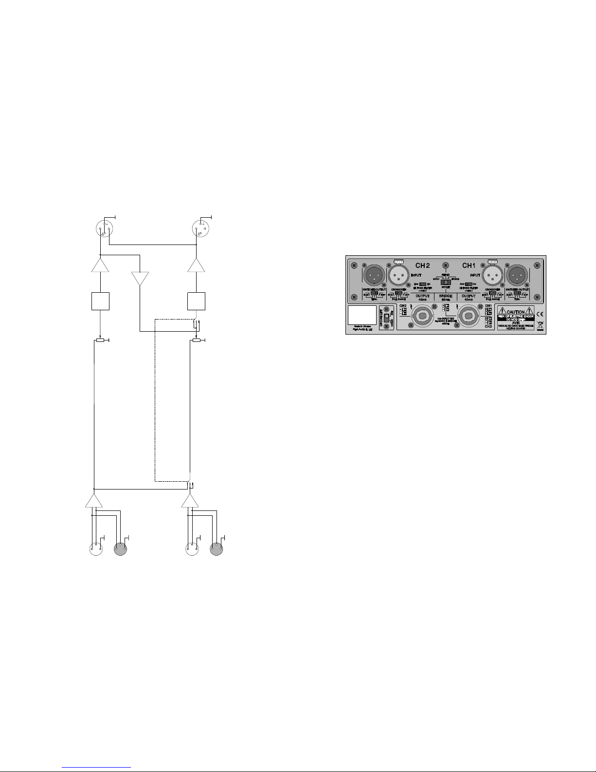
Balanced Inputs
The use of balanced inputs provides for an essential reduction of the environment-
induced hum and noise interference with long input connecting cables.
Input Level Attenuators
Located on the front panel, these allow setting the amplifier to the required sensitivity
(each channel individually) which is very helpful when several amplifiers run in parallel,
especially when they drive different types of speaker systems or are used within multi-
speaker sound reinforcement systems.
Output Power:
–V4-900 MkIII 450 W (channel, 4Ohm, 230V)
280 W (channel, 8Ohm, 230V)
900 W (bridge, 8Ohm, 230V)
–V4-1200 MkIII 600 W (channel, 4Ohm, 230V)
330 W (channel, 8Ohm,230V)
1200W (bridge, 8Ohm,230V)
–V4-1800 MkIII 900 W (channel, 4Ohm, 230V)
500 W (channel, 8Ohm, 230V)
1450W (bridge, 8Ohm,230V)
–V2-2400 MkIII 1200W (channel, 2Ohm, 230V)
700 W (channel, 4Ohm, 230V)
380 W (channel, 8Ohm, 230V)
2000W (bridge, 4Ohm,230V)
1400 W (bridge, 8Ohm,230V)
–V4-2400 MkIII 1200W (channel, 4Ohm, 230V)
700 W (channel, 8Ohm, 230V)
2000W (bridge, 8Ohm,230V)
Peak Output Power:
–V4-900 MkIII 700 W (channel, 4Ohm, 10ms, 230V)
350 W (channel, 8Ohm, 10ms, 230V)
1400W (bridge, 8Ohm, 10ms, 230V)
–V4-1200 MkIII 900 W (channel, 4Ohm, 10ms, 230V)
450 W (channel, 8Ohm, 10ms, 230V)
1800W (bridge, 8Ohm, 10ms, 230V)
–V4-1800 MkIII 1250W (channel, 4Ohm, 10ms, 230V)
625 W (channel, 8Ohm, 10ms, 230V)
2500W (bridge, 8Ohm, 10ms, 230V)
–V2-2400 MkIII 1800W (channel, 2Ohm, 10ms, 230V)
900 W (channel, 4Ohm, 10ms, 230V)
450 W (channel, 8Ohm, 10ms, 230V)
3600W (bridge, 4Ohm, 10ms, 230V)
1800W (bridge, 8Ohm, 10ms, 230V)
–V4-2400 MkIII 1700 W (channel, 4Ohm, 10ms, 230V)
850 W (channel, 8Ohm, 10ms, 230V)
3400W (bridge, 8Ohm, 10ms, 230V)
SPECIFICATIONS
2-conductor

6 27
Built-in Two-Way Crossover
(only for input modules with a crossover)
This feature allows to pick up the respective frequency range both for this amplifier and
for any other equipment connected to it (such as another amplifier or an active speaker
system). The amplified frequency range can be set individually for each channel. The
crossover allows to switch between two preset crossover frequency settings. The desired
frequency setting is selected with a slide switch. The crossover allows individual setting of
both the signal frequency range (high, low, full-range signal) being sent to the line output,
and the signal frequency range to be amplified by the amplifier itself. Such switching features
allow to create two-way sound reinforcement systems driven by two amplifiers, a V-series
amplifier being one of them.
In addition, it is possible to change the input stage crossover frequency by replacing
standard crossover filters with custom ones. For more information about installation and
purchasing the crossover filters, please, consult our local dealer or the manufacturer’s
support service by e-mail: support@parkaudio2.com
Line Outputsch)
The amplifier line outputs are parallel to the inputs (each along the respective channel)
and provide for parallel connection of several amplifiers with standard signal cables using
XLR connectors.
Switch-Selectable Active Line Output
(only for input modules with a crossover)
This feature allows to send the line signal to another amplifier. If this is the case, the
output can be set to deliver either the whole (full-range) signal (for two parallel amplifiers fed
from a common signal source) or its required frequency component (high or low) processed
up by the built-in crossover (when two-way systems are in operation). The connection to the
line output is done with XLR connectors. The output frequency range can be set with a slide
switch located on the rear panel. The amplifier’s line outputs are parallel to the inputs (each
along the respective channel). They make it possible to link up with several parallel amplifiers
interconnected with XLR-wired signal cables.
Sensitivity Switch
(only for input modules with a sensitivity switch)
This switch allows to select the required sensitivity of the amplifier, viz. 0.775V, 1.4V
or to set the fixed gain rate of 32dB.
Sensitivity is selected with a slide switch (individual for each channel) located on the
amplifier’s input module.
Input Filter
(only for input modules with a sensitivity switch or with a crossover)
To improve the performance of speaker systems, the amplifier incorporates a switch-
selectable high-pass 4-th order filter with a 24dB per octave slope rate. This is the filter
recommended by all major speaker systems manufacturers.
This filter cuts off any signals below 35Hz, which generally cannot be reproduced by
most of the professional speaker systems.
The filter significantly reduces the travel of the LF loudspeaker cone below the
loudspeaker frequency cut-off point. Especially, this is the case when phase inversion
systems are used. Therefore, the filter makes it possible to increase the power applied to
TROUBLESHOOTING
No Sound Signal on the Amplifier`s Output
POWERLEDisOFF:
–power cable is damaged;
–no power.
But for POWER LED all other LEDs are OFF:
–no input signal;
–input level attenuators are set to minimum position.
CLIP LED goes ON while output level LEDs are OFF:
–output cable is short-circuited;
–load impedance is too low.
ALARMLEDgoesON:
–the unit is in the DC-protection mode;
–the unit is in the HF protection mode.
The problem may be with the signal source. Try disconnecting the signal source from
the amplifier.
Sound Distortion
SIGNAL LED is ONwhile CLIP LED isOFF:
–applied input signal is distorted before it gets to the amplifier;
–speakers are damaged.
If input attenuators are set close to their minimum position, distortion may occur as a
result of input stage overload with high input signal.
BothSIGNALand CLIP LEDs are ON:
–overload caused by low impedance or high input signal.
Low frequency is missing in the response
(only when an input module with a crossover is installed)
Wrong crossover settings (CROSSOVER switch is set to HI).
Speaker systems may be damaged, or low frequency is missing in the input signal.
High frequency is missing in the response
(only when an input module with a crossover is installed)
Wrong crossover settings (CROSSOVER switch is set to LO).
Speaker systems may be damaged, or high frequency is missing in the input signal.
Hum and Interference
Be sure to have the power cable 3-wire plug properly connected to the grounded outlet.
Disconnecting the ground contact usually does not eliminate hum and interference, but may
pose a risk of electric shock.
To reduce hum and noises, use balanced connections.
It is recommended to have the GROUND LIFT switch set to GROUNDED to preclude
potential electric shock hazard. However, sometimes hum may be caused by current flow
through ground loops. In this case, setting GROUND LIFTto UNGROUNDED may resolvethe
problem.

726
the LF loudspeaker (the power being not wasted for the cone “flapping”) and thus to raise
the sound pressure created by the speaker system without any danger of overheating the
LF drivers.
When it is necessary to achieve a linear frequency response to drive full-range speaker
systems generally used in studios or in cinema theatres, the input filter can be disabled
(bypassed for each channel individually) with the slide switches located on the amplifier rear
panel.
See below the enabled and disabled filter low frequency response diagrams.
Replaceable Input Module (Option)
This feature allows the owner to replace the standard input module with an input
module having an input sensitivity switch or with the one containing a crossover. For any
details as to purchasing and installation of the replaceable modules, please, contact our
local dealers, or send your e-mail messages to: support@parkaudio2.com.
Operating Modes
STEREO –two channels drive two separate loads from two separate signal sources.
MONO –two channels drive two separate loads from a single input signal source.
BRIDGE –two channels drive the same load from a single signal source.
The operating modes can be selected with the slide switch located on the rear panel.
Ground Lift
This slide switch is used to decouple the signal ground and the chassis ground in order
to reduce AC noise when several amplifiers are connected together.
Removable Power Cord
This feature is provided for convenience of transportation and rack mounting.
Low Frequency Response for Different Settings
of the Input Filter Switch
20Hz 50Hz 100Hz 200Hz 900Hz
-10
-5
0
5
10
«ON »
20Hz 50Hz 100Hz 200Hz 900Hz
-10
-5
0
5
10
«OFF»
Linking up Signal and Speaker Systems in Case of Single Amplifier Operation
within a Two-Way Mono Set
(only when an input module with a crossover is installed)
Input Signal Source
Subwoofer Satellite
Crossover Settings in Case of Operation of a Single Amplifier within
a Two-Way Mono Set
CHANNEL 2
SWITCHEDOUTPUT–any position
CROSSOVER –LO position
CHANNEL 1
SWITCHEDOUTPUT–any position
CROSSOVER –HI position

8 25
Crossover Settings in Case of Operation of Two Amplifiers within
a Two-Way Stereo Set
(Option 2)
Amplifier 1
CHANNEL 2
SWITCHEDOUTPUT–HI position
CROSSOVER –LO position
CHANNEL 1
SWITCHEDOUTPUT–HI position
CROSSOVER –LO position
AMPLIFIER BLOCK DIAGRAM
Power
amplifier
Power
amplifier
Limiter
Limiter
C
H
1
INPUT
THROUGH
MONO
STEREO
BRIDGE
MODE
1
+
1
+
2
+
2
+
O
U
T
P
U
T
O
U
T
P
U
T
CH 2
INPUT LEVEL
LEVEL
THROUGH

24 9
Amplifier 2
Amplifier 1
Linking up Signal and Speaker Systems in Case of Operation of Two Amplifiers
within a Two-Way Stereo Set
(Option 2)
(only when an input module with a crossover is installed)
To Channel 1
Input Signal Source
To Channel 2
Input Signal Source
Channel 2
Satellite Channel 1
Satellite
Channel 2 Subwoofer Channel1 Subwoofer
AMPLIFIER BLOCK DIAGRAM
(for input moduleswith a sensitivity switch)
.775V
1.4V
32dB
G
A
I
N
Power
amplifier
Power
amplifier
Limiter
Limiter
CH 1
INPUT
THROUGH
MONO
STEREO
BRIDGE
MODE
LEVE
L
LEVE
L
ON
OFF
HI PASS FILTER
35Hz
ON
OFF
HI PASS FILTER
35Hz
1
+
1
+
2
+
2
+
O
U
T
P
U
T
O
U
T
P
U
T
CH 2
INPUT
THROUGH
.775V
1.4V
32dB
GAIN

10 23
Crossover Settings in Case of Operation of Two Amplifiers within
a Two-Way Stereo Set
(Option 1)
Amplifier 1
CHANNEL 2
SWITCHEDOUTPUT–LO position
CROSSOVER –HI position
CHANNEL 1
SWITCHEDOUTPUT–LO position
CROSSOVER –HI position
AMPLIFIER BLOCK DIAGRAM
( for input modules withcrossover)
CROSSOVER
CROSSOVER
HF
LF
HF
LF
HI
FULL RANGE
LO
CROSSOVER
LEVEL
LEVEL
HI
FULL RANGE
LO
CROSSOVER Power
amplifier
Power
amplifier
Limiter
Limiter
C
H
1
INPUT
SWITCHED OUTPUT
LO
THRU
HI
SWITCHED OUTPUT
LO
THRU
HI
MONO
STEREO
BRIDGE
MODE
125Hz
125Hz
125Hz
125Hz
ON
OFF
HI PASS FILTER
35Hz
ON
OFF
HI PASS FILTE
R
35Hz
1
+
1
+
2
+
2
+
O
U
T
P
U
T
O
U
T
P
U
T
CH 2
INPUT

1122
Linking up Signal and Speaker Systems in Case of Operation of Two Amplifiers
within a Two-Way Stereo Set
(Option 1)
(only when an input module with a crossover is installed)
To Channel 1
Input Signal Source
To Channel 2
Input Signal Source
Amplifier 2
Amplifier 1
Channel 1 SatelliteChannel 2 Satellite
Channel 2 Subwoofer Channel 1 Subwoofer
FRONT PANEL
Power switch.
LEVEL –input signal attenuators for channel 1 & 2, respectively.
ALARM LEDs.
Indicate alarm status and protection of the respective channel in case of:
–DC output condition or powerful LF fluctuations;
–output stage overheating*
Note:
* See: page 5, Thermal Protection.
CLIP (overload) LEDs.
Indicate overloading (sound distortion) and limiter activation for the respective
channel.
SIGNAL LEDs.
Indicate signal output from channel 2 & 1, respectively.
POWER LED

2112
Linking up Signal and Speaker Systems in Case of Parallel Operation of Two
Amplifiers within a Full-Range Stereo Set
To Channel 1
Input Signal Source
To Channel 2
Input Signal Source
Channel 2 Speaker Channel 1 Speaker
Amplifier 2
Amplifier 1
THROUGH –line outputs for Channel 2 & 1, respectively (XLR male).
Are used to deliver input signal along the respective channel to the input of another
amplifier.
THROUGH connectors are parallel to INPUT connectors of respective channels.
INPUT –Channel 2 balanced input (XLR female).
Is used to supply input signal to channel 2.
MODE switch.
–MONO –two channels drive two separate loads from a single input signal source;
–STEREO –two channels drive two separate loads from two separate input signal
sources;
–BRIDGE –two channels drive a common load from a single input signal source.
INPUT –balanced input (XLR female) for Channel 1 in STEREO; Channels1 and 2 in
MONO; BRIDGE mode.
MAINS IN –power cord socket for 230V AC 50/60Hz grounded mains.
OUTPUT –Channel 1 output.
Is used to connect a load (speaker system) to Channel 1 with a SPEAKON®connector,
as well as to connect a load (speaker system) to the amplifier in BRIDGE Mode. In
addition, Channel 2 output is linked to Channel 1 output socket thus making it possible
to connect the speaker systems of both channels to this output socket with a single
NL4FC connector (wired accordingly).
OUTPUT –Channel 2 output.
Is used to connect a load (speaker system) to Channel 2 with a SPEAKON®connector.
GROUND LIFT switch.
REAR PANEL
Channel 2
Speaker Channel 1
Speaker

20 13
Linking up the Signal and Speakers in BRIDGE Mode
CAUTION! Never attempt to jumper or otherwise link up any pins of output connectors.
To Speaker
To Input Signal Source
BRIDGE Mode
Input signal is linked up to Channel 1 input connector.
Speaker is linked up to Channel 1 output of with NL4FC SPEAKON.
MODE switch is set to BRIDGE.
Use channel 1 LEVEL control to adjust the level of the input signal (located on the front
panel).
(Only for input modules with a sensitivity switch or crossover)
For most applications, it is recommended to set the input HI PASS FILTER switches to
ON. In this mode, only the Channel 1 switch is enabled. However, when it is necessary to
obtain a liner frequency response to drive full-range speaker systems, as in studios or
cinema houses, set this input filter switch to OFF. See the Input Filter Section.
INPUT MODULE WITH SENSITIVITY SWITCH (Option)
THROUGH –line outputs for Channel 2 & 1, respectively (XLR male).
Are used to deliver input signal along the respective channel to the input of another
amplifier.
THROUGH connectors are parallelto INPUT connectors of respective channels.
GAIN –input sensitivity switches for Channel 2 & 1, respectively.
Are used to select the input sensitivity (0.775V, 1.4V) or fixed gain (32 dB) for
respective channel.
INPUT –Channel 2 balanced input (XLR female).
Is used to supply input signal to channel 2.
HI PASS FILTER –cutoff filter switches for Channel 2 & 1, respectively.
Are used to enable/disable input high-pass filter of the respective channel(See: Input
Filter).
MODE switch:
–MONO –two channels drive two separate loads from a single input signal source;
–STEREO –two channels drive two separate loads from two separate input signal
sources;
–BRIDGE –two channels drive a common load from a single input signal source.
INPUT –Channel 1 balanced input (XLR female).
Is used to supply input signal to channel 1, channel 1 and 2 (in MONO mode), and a
common input signal(in BRIDGE mode).
MODE switch
is set to
BRIDGE

1914
SWITCHED OUTPUT (switch-selectable output) –line output for channels 2 & 1,
respectively. Used to deliver signal to the input of another amplifier (when several
amplifiers are fed from a common input signalsource).
INPUT –Channel 2 balanced input (XLR female).
It is used to supply input signal to channel 2.
HI PASS FILTER enable/disable switches for Channel2 & 1, respectively (See: Input
Filter).
MODE switch.
–MONO –two channels drive two separate loads from a single input signal source;
–STEREO –two channels drive two separate loads from two separate input signal
sources;
–BRIDGE –two channels drive a common load from a single input signal source.
INPUT –balanced input (XLR female) for Channel 1 in STEREO; Channels1 and 2
inMONO;BRIDGEmode.
Line output switches for channel 1 & 2, respectively
Select required frequencyrange of the signaldelivered to theoutput ofthe respective
channel:
–HI;
–LO;
–THRU –full-range signal.
The switches affect only the signal delivered to the output of the respective channel.
CROSSOVER switch for channel 1 & 2, respectively.
Selects the desired frequency range to be amplified:
–HI;
–LO;
–FULL RANGE.
The BRIDGE mode, the frequency range is set by Channel1 CROSSOVER switch.
INPUT MODULE WITH CROSSOVER (Option)
Linking up the Signal and Speakers in MONO Mode
CAUTION! Never attempt to jumper or otherwise link up any pins of output connectors.
To Channel 2 Speaker
MONO Mode
Input signal is linked up to Channel 1 input connector.
Speakers are linked up to the output of respective channels with either NL4FC or
NL2FCSPEAKON.
MODE switch is set to MONO.
To adjust the level of input signal, use a LEVEL control of each channel (located on the
front panel).
(Only for input modules with a sensitivity switch or crossover)
For most applications, it is recommended to set the input HI PASS FILTER switches to
ON. However, when it is necessary to obtain a liner frequency response to drive full-range
speaker systems, as in studios or cinema houses, set this input filter switch to OFF. See the
Input Filter Section.
To Input Signal Source
MODE switch
is set to
MONO
To Channel 1 Speaker

1518
CABLE REQUIREMENTS
Input Cables
Make sure to use only shielded cables whether balanced or unbalanced. Shielding
when properly grounded protects a signal against external electrical interference.
As a rule, unbalanced lines of over 3 meters long are not acceptable. Greater distances
require a balanced cable. Avoid placing input cables close to power cords or power
transformers.
Output Cables
The amplifier is capable of delivering high level output current; therefore, the wire
gauge used for speaker cables is particularly important. Inadequate wire gauge adds
significant resistance to the speaker’s own impedance, reducing the power which is actually
delivered to the speaker. It will also result in a decreased damping factor and possible fire
hazard.
Since the power applied to the loudspeaker is of primary concern in system design, we
have included the table below to allow you determine the appropriate wire gauge for your
application.
The table shows the percentage of the power loss in a 10-meter copper multiple-core
cable. This table reflects the power loss as a percentage of the output power of the amplifier
applied to the load. Use this table to determine the power loss to the load at other cable
lengths. For example, if you plan to deliver 500Watts to 8-Ohm load through 20m of 1,5-mm2
cable, the power loss in thecablewould be 2,9 % x 2=5,8 % of 500W or 29W lost in the cable.
WireGauge Cable
Resistance
Cable power loss
8Ohm load
1,5mm2
2,0mm2
2,5mm2
4,0mm2
0,24 Ohm
0,18 Ohm
0,15 Ohm
0,09 Ohm
10,7%
8,3%
7%
4,3%
2,9%
2,2%
1,8%
1,1%
2Ohm load
5,7%
4,3%
3,6%
2,3%
4Ohm load
Power Loss in a 10-meter Cable
OPERATING MODES
STEREO Mode
Two input signals are linked up to the input connectors of respective channels.
Speakers are linked up to the output of respective channels with either NL4FC or
NL2FCSPEAKON.
MODE switch is set to STEREO.
To adjust the level of input signal, use a LEVEL control of each channel (located on the
front panel).
(Only for input modules with a sensitivity switch or crossover)
For most applications, it is recommended to set the input HI PASS FILTER switches to
ON. However, when it is necessary to obtain a liner frequency response to drive full-range
speaker systems, as in studios or cinema houses, set this input filter switch to OFF. See the
Input Filter Section.
Linking up the Signal and Speakers in STEREO Mode
CAUTION! Never attempt to jumper or otherwise link up any pins of output connectors.
To Channel 1 SpeakerTo Channel 2 Speaker
To Channel 1
Input Signal Source
To Channel 2
Input Signal Source MODE switch
is set to
STEREO

1716
INPUT AND OUTPUT CONNECTORS
Input Connectors
Use XLR (male) connectors to connect to the amplifier inputs and XLR (female)
connectors to line outputs.
See the wiring on the figures below.
Output Connectors
To connect speaker systems to the outputs of the amplifier, use the SPEAKON NL2FC
or NL4FC connectors in the channel modes. Use SPEAKON NL4FC connectors for bridged
connection or connection of two channels with a single connector
CAUTION! Never attempt to jumper or otherwise link up any pins of output connectors.
2
1
3
Balanced Input Cable Wiring
(XLRmale)
Shield(Ground)
Cold(–)
Hot (+)
Balanced Line Ouput Connection
Cable Wiring (XLRfemale)
2
1
3
Shield(Ground)
Cold(–)
Hot (+)
a)for STEREO and MONO MODE
(Channel 1 and Channel 2 Connectors) b) forBRIDGE MODE
out (+) out (–)out (–) out (+)
Speaker System Connector Wiring
Channel 2
out (+)
Channel 1
out (+)
Channel 1
out (–)
Channel 2
out (–)
c) for connecting two channels with a single connector
RACK-MOUNTING REQUIREMENTS
The amplifier is designed to fit a standard 19”rack. While mounting, make sure to
provide unhindered air access to the front and rear sides of the rack. Fan direction is from
front to back. It is not necessary to leave empty space above or below the amplifier.
For stationary use, it will be enough to fix securely only the front panel of the amplifier
to the rack. However, never attempt to transport the unit unless its rear end is properly
supported and/or securely fixed, as it may be fraught with danger of damage.
AC POWER REQUIREMENTS
1.TheV4-900MkIII,V4-1200MkIII,V4-1800MkIII,V4-2400MkIII,V2-2400MkIIIamplifiersare
supplied with a three-conductor grounded AC power cord, and should be plugged into a
standard 3-wire grounded electrical outlet which supplies 230VAC 50/60Hz. Make sure to
connect the amplifier only to sufficiently powerful power supply mains (closer to a switch-
board). If connected to weak power supply mains, the output power of the amplifier may be
reduced producing the so-called «feeble bass» effect, or the power supply line may be
damaged.
Never try to connect the amplifier to a household power supply mains.
Use the power cord supplied to plug the amplifier into the mains. Prior to plugging,
please, make sure that there are no other devices consuming much AC current, as the
normal operation of such several devices may beimpossible. In the event of line voltage sag,
the unit will continue to operate normally, albeit with less power.
2. The actual AC current consumption by the amplifier depends on the type of the music
program and the load impedance. While installing the audio systems, to optimize the power
wiring, please, note that for reproduction of typical audio material at the full output level, the
average current consumption rate is as follows:
–3A for V4-900 MkIII into 8Ohm;
–6A for V4-900 MkIII into 4Ohm;
–4A for V4-1200 MkIII into 8Ohm;
–8A for V4-1200 MkIII into 4Ohm;
–5A for V4-1800 MkIII into 8Ohm;
–10A for V4-1800 MkIII into 4Ohm;
–4A for V2-2400 MkIII into 8Ohm;
–8A for V2-2400 MkIII into 4Ohm;
–16A for V2-2400 MkIII into 2Ohm;
–8A for V4-2400 MkIII into 8Ohm;
–16A for V4-2400 MkIII into 4Ohm.
3. In order to minimize the AC current hum and noise, make sure to plug all audio
devices interconnected with signal cables, into the same mains outlet.
This manual suits for next models
4
Table of contents
Other Park Audio II Amplifier manuals