Park Audio II DX1000MB User manual

OWNER’S MANUAL
PARKAUDIOII
www.parkaudio2.com

AVIS
RISQUE DE CHOC ELECTRIQUE
NE PAS OUVRIR
CAUTION! The amplifier runs on 230 V AC voltage. Removing the cover willexpose you
to a potentially dangerous voltage!Do not use the unit ifthe electrical power cord is frayed
or broken. Power is supplied from 230 V AC single-phase grounded 50/60 Hz source!
CAUTION! The amplifier can yield dangerous outputvoltage! Do notinstallan energized
unit into the speaker system.Do not touch the non-insulatedcable parts connected to the
unit in operation!
CAUTION! The high sound pressure levelof speakersystems generated by high output
power delivered by the amplifier may be hazardous to your hearing. Please, take adequate
safety precautions.
WARNING! The amplifier yields high output power. The manufacturer shall not be held
responsible for any damage to the speakers caused by excessive power from the unit.
WARNING SIGNS:
Important information! Intended to alert the user of the presence of
important operating and maintenance (servicing) instructions in the Owner’s
Manualaccompanyingtheproduct.
Hazardous voltage inside! Intended to alert the user to the presence of
uninsulated “dangerous voltage”within the product’s enclosure that may be of
sufficient magnitude to constitute a risk of electric shock to persons.

INTRODUCTION
DX1000MB built-in power amplifier is intended for use in LF speaker systems
(subwoofers).
UNPACKING
The manufacturer’s quality control system provides for careful examination of each
product before it leaves the factory to ensure its flawless appearance. After unpacking,
please,check theunit foranyphysicaldamage.Incase ofdamage, please,contact our local
dealer. Keep the shipping carton and allpacking material, as you may require them for re-
shipment of the unit.
12
DIMENSIONS
ACCESSORIES
1. Power cord 1 ea.
2. Owner’s Manual 1 ea.
3. Warranty 1 ea.
139
827
252.5
3
6
4
.
5
391.5
4
0
7
.
5
91
8182
198
1527 max
156 max
2
4
2
6
0
.
5
16
3
6
1
.
5
3
6
6
m
a
x
102
2

DESIGNANDFUNCTIONALFEATURES
Design
The built-in.power amplifier is designed as a mono-block unit. All its components are
installedonasingle bearingpanelplacedinsidethecasewhichprotectstheunitandensures
its deep placement into the body of a speaker system.
Power to the built-in power amplifier is supplied via a removable power cord.
The amplifier incorporates:
–power supply source;
–power amplifier;
–input section.
Power Supply Source
Switcheable. Made to minimizethe weight ofthe amplifier.
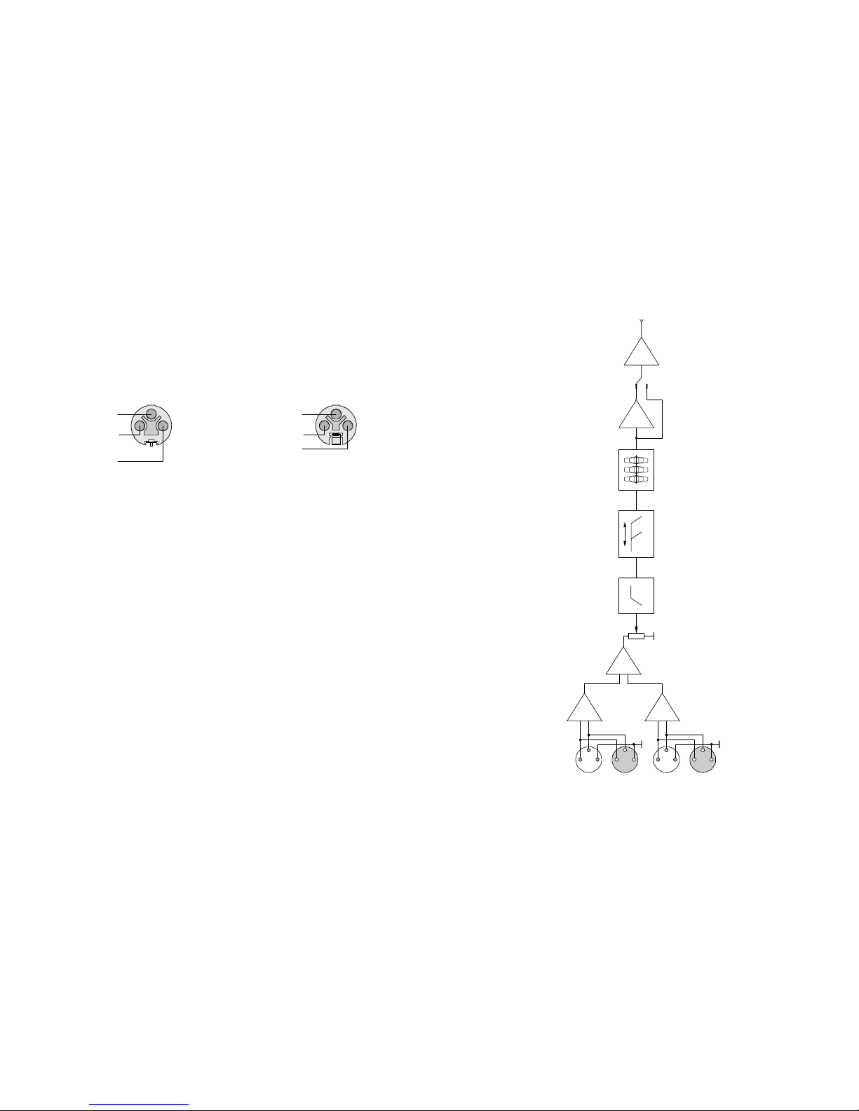
Power Amplifier Schematics
The power amplifier is designed according to Class D technology to deliver high
efficiencyandleastheat.Thehighswitching rateensuresthehighsoundqualitycomparable
with the best analogue amplifiers.
Cooling System
The amplifier is cooled down with a fan. The cooling system ensures reliable cooling
withinthe whole operating temperature range (5 to 35°Ñ). The cooling system is a double-
mode system whichensures smooth coolingintensity rate switchingin the fan-ON mode. At
a normal temperature and low output level the fan is OFF, thus generating no noise. When
the amplifier is set to deliver a high output power, as well as when the ambient temperature
is higher than normal and when the heat sink becomes too hot, the fan goes ON, and the
cooling intensity rate changes smoothly as the temperature rises.
Overload and Short-Circuit Protection
This protective system becomes active in case of short-circuited output or overload
caused byreduced load impedance. It disables the output signalof the respective channel
for 0.5 second and then the amplifier gradually resumes its delivery.
DC Output Protection
Theamplifier’s schematics precludes transit of any clicks or noise during the power-on/
off transition process. Moreover, the amplifier protects the speaker system where it is
installed against damage by DC voltage or powerful LF fluctuations in case of their
occurrence onthe outputof theamplifier.Inthis case itspowersourcegoes offandallLEDs
go off too, including the POWER LED.
The power amplifier can be restarted by consecutive switching OFF and ON with the
POWERkey.IftheDCisanoccasionalproblem(whichisunlikely)theamplifiergoesONand
resumes its normal functioning. If, otherwise, the DC output problem persists through the
fault of the amplifier, thenupon switching, the amplifier goes ON but ina short while the DC
output protection system disables the power supply source.
11
SPECIFICATIONS
Output Power: 1000W (8Ohm,100Hz,230V)
Peak Output Power: 1200W (8Ohm,10ms, 230V)
Frequency Response*: 45 Hz –80...350 Hz (1000W, 8Ohm)
Total
Harmonic Distortion: 0.05% (45Hz-350Hz,8Ohm)
Slew Rate: 20 V / µs (LF filter disabled)
Damping Factor: over 200 (100Hz, 8Ohm)
Signal-to-Noise Ratio: 98dB (unweighted)
Sensitivity: 775 mV
High-pass
Filter Cutoff Frequency: 45Hz (basic model)
High-pass Filter Slope: 24 dB/oct
Low-pass Crossover
Filter Cutoff Frequency: 80 –350 Hz
Crossover Low-pass
Filter Slope: 12 dB/oct
Power Requirements: AC230V,50/60Hz
Weight: 4kg
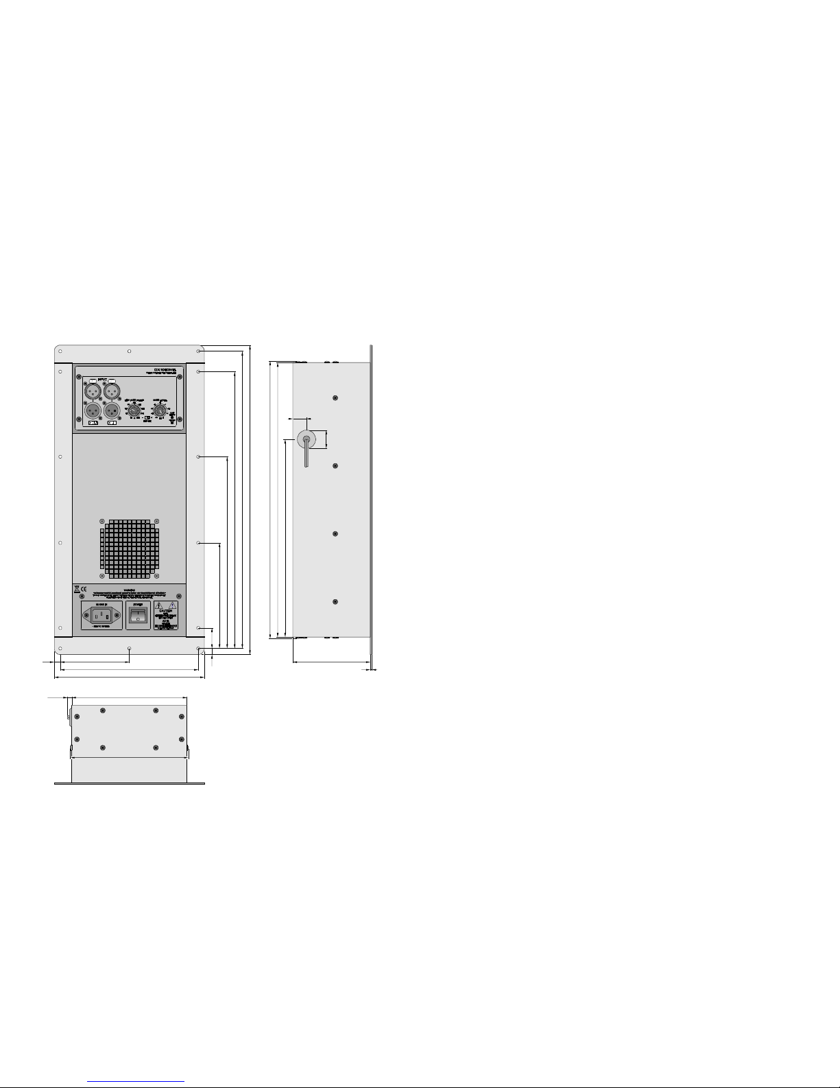
Dimensions: 198 mm (width)
407.5 mm (height)
104 mm (depth)
Note:
* The basic model frequency response which can vary depending on the filter frequency settings.
2

10 3
Thermal Protection
The thermalprotection system ensuresthe amplyfier’s reliable and faultless operation
in case of overheating. The fan is completely OFF until the temperature of the heat sink
reaches 50°Ñ. When the heat sink temperature exceeds 50°Ñ, the cooling fan goes ON at
its least speed. Any further rise of temperature results in a smooth increase of the cooling
intensity rate up to 70°Ñ. At the same time, when the temperature rises to 65°Ñ, the built-
inoptoelectronic Clip-limiter becomes active reducing the input signal levelon the amplifier
input without distorting thesound. Inthiscase, the thermal protection LED becomes slightly
lit (dim). The higher the temperature, the lower signal level, the brighter is the LED.
The signalmay be cutoff only in case of the fan breakdown orblocked air flow. If this
is the case, the thermal protection system disables the input signal when the heat sink
temperature has reached 85°Ñ, this state being indicated by the CLIP/THERM LED.
The amplifier resumes its operation inthe reverse order as soon as has cooled down,
gradually regaining its amplification level up to the set value.
Soft Signal Start
This feature ensures smoothsignal volume increase on power-on and on resumption
of operation of the unit after an alarm condition to avoid any undesirable impact on the
loudspeakers.
Indication
TheindicationconsistsoftwoLEDs,oneofwhichindicatesthepoweroncondition,and
the other the overload condition and thermal protection active condition.
Input Section
The input section incorporates:
–two line input (XLR female);
–two line output (XLR male);
–low-pass filter control knob;
–output signal phase slide switch.
The amplifier inputs are balanced.
The line input and output connectors are parallel, i.e. the contacts of the output
connector match the respective contacts of the input connector. This allows to use the
amplifier as a signal patching unit (e.g. for supplying the signal to active satellite speaker
systems), while the unit itself amplifies the summed signal taken from both inputs.
The levelcontrol knob is used to adjustthe level of the signalsupplied to the amplifier.
The low-pass filter control knob allows to set the upper frequency limit of the amplifier
bandwidth(between 80Hzand350Hz).
The output signalphase slide switch is provided for 180° reversing of the signal phase
inordertoachievethebestcompatibilityofthesoundsignalphaseofthesubwoofer(inwhich
this amplifier is installed) with other loudspeakers within the same sound reproduction
system.
TROUBLESHOOTING
No Sound Signal on the Output
POWERLEDisOFF:
–power cable is damaged;
–no power.
POWERLEDisONwhileCLIP/THERMLEDisOFF:
–no input signal;
–input level knobs are set to minimum position.
POWERandCLIP/THERMLEDsareON:
–load impedance is too low, or short-circuited load;
–active overheating protection.
The problem may be caused by the input signal source. Try disconnecting the input
signal and check the result.
Sound Distortion
–applied input signal is distorted before it gets to the amplifier;
–high input signal;
–speakers are damaged.

4
To signal source
Channel A
line output
To signal source Channel B
line output
LINKINGOFINPUTSIGNALTOAMPLIFIER
The Cutoff and Crossover Filters
The amplifier incorporates:
–high-pass fourth-order cutoff filter (signal slope –24dB/oct.);
–fine-adjustable second-order low-pass crossover filter (signal slope –12dB/oct.).
The high-pass fourth-order cutoff filter is used for eliminationof signal LF components
which cannot be reproduced by the speaker system.
The basic model has the high-pass cutoff filter set to 45Hz.
The low-pass crossover filter is used to limit the amplified frequency range to be
compatible with the subwoofer application.
The cutoff point of the low-pass filter can be set by the control knob within the range
of80Hzto350Hz.
Built-in Parametric EQ
The EQ provides the parametric correction of the amplifier frequency response.
The correctioniseffectedinthreepoints withadjustmentoftherespectiveQ value and
boost/cutparameters.TheEQispresetbythemanufactureras requestedbythecustomer.
The customer-required parameters are shown on the label pasted on the amplifier
casing.
9

58
DX1000MB BLOCK DIAGRAM
INPUT
CHA
45Hz 80 - 350Hz
CHB
BASS
LEVEL
LOW PASS
FILTER
BASS
LEVEL
Hi Pass Filter Built-in
3 Parametric EQ
_
+
P
H
A
S
E
O
U
T
P
U
T
2
1
3
2
1
3
Balanced Input Cable Wiring
(XLRmale)
Shield
(Ground)
Cold (–)
Hot (+) Shield
(Ground)
Cold (–)
Hot (+)
Balanced Line Ouput Connection
Cable Wiring (XLR female)
INPUT CONNECTORS
Use XLR (male) connectors for the inputs and XLR (female) connector for the line
outputs. See the wiring on the Figure below.
ACPOWERREQUIREMENTS
The unit is supplied with a three-conductor grounded AC power cord, and should be
plugged intoa standard3-wiregroundedelectricaloutletwhichsupplies230VAC50/60Hz.
Intheeventoflinevoltagesag,theunitwillcontinuetooperatenormally,albeitwithless
power.
The actual AC current consumptionby the amplifier depends on the audio signal level
and the load impedance.
For typicalaudio program materialwiththeamplifierdrivingboth channelsjustpeaking
at the clipping level, the AC line current capacityof 2A is recommended for system design
purposes.
INSTALLATION INTO A SPEAKER SYSTEM
Insert the amplifier into the cutout in the rear panel of a speaker system.
For installation of the amplifier we recommend a cutout of the following size:
–height 369mm;
–width 158mm.
The amplifier is designed to be operated under permanent vibration conditions and
does not require special tight sealing of the compartment where the unit is to be installed.
However,toimprovethesoundqualityofthespeakersystem,themanufacturerrecommends
to install the amplifier into a compartment enclosed from the inner space of the speaker
system.

76
DX1000MBCONTROLSANDCONNECTORS POWER –power switch.
AC230V 50/60 Hz –power cable socket.
ATTENTION!Thepowertotheamplifierissuppliedfromsingle-phaseACpowermains
withprotectivegrounding.Toconnecttheamplifiertoawalloutlet, firstinsertthe power
cord into the power cord socket and then plug it into the wall outlet.
Channel B line output (XLR male): parallel to Channel B input.
Channel A line output (XLR male): parallel to Channel A input.
Channel A input (XLR female)*.
Channel B input (XLR female) *.
LOW PASS FILTER –low-pass filter cutoff point knob: sets the bandwidth upper
frequency (80Hz ... 350Hz).
BASS LEVEL –input level control knob.
Used to adjust the level of the input signal applied to the power amplifier.
CLIP / THERM –overload/thermal protection LED
Indicating:
–overload condition characterized by sound distortion and optoelectronic clip-limiter
active mode;
–thermal protection active condition. (See: Thermal Protection above).
POWERLED.
Incase of active DC protection system, the LED goes off.
PHASE –output signal phase slide switch. Used to set the required phase of the output
signal:
–+–signal phase unchanged;
–––signal phase 180° reversed.
Note:
* The unit amplifies the summed signal taken from the Channel A and Channel B inputs.
Table of contents
Other Park Audio II Amplifier manuals