PARK WAREHOUSE 605wf120-2 User manual

PAGE 1
INSTALLER
To assure you install these models easily and correctly, PLEASE READ THESE SIMPLE
INSTRUCTIONS BEFORE STARTING THE INSTALLATION. CHECK YOUR INSTALLATION FOR
COMPLIANCE WITH PLUMBING, ELECTRICAL, AND OTHER APPLICABLE CODES. After
installation, leave these instructions with the Fountain for future reference.
Outdoor StandFreeStationFilingBottleSKU: 605wf120-2 Installation

PAGE 2
INSTALLATION INSTRUCTIONS FOR INSTALLING SANITARY FREEZE
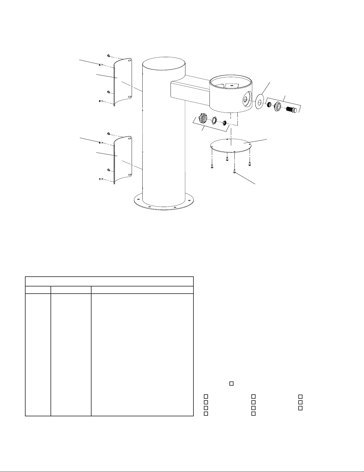
SINGLE VALVE CONTROL ASSY.
1. Prepare trench for water supply and waste drain lines (if required by local codes). The hole should be deep enough to accommodate the PVC column and 5 cubic feet
ofporousll(largebrokenrock).Additionalporousllmayberequiredduetolocalgroundconditions.(SeeSitePreparationDetail.)
2. Lay drain lines and water supply lines. Provide service shut off valve for maintenance. Flush the water supply line before attaching to the shut off valve.
3. Set PVC column in excavating pit. Connect the water supply line to the inlet on the PVC column. Remove valve assembly from the PVC column by carefully
pulling up on the nylon strap. Pressure test the valve assembly for leaks. Check operation of the water valve by blowing on the small clear diameter tubing.
Asteadystreamofwatershouldowfromthebraidedtubing.Afterreleasingairpressurefromthesmallcleartubingthewaterstreamshouldstop.
4. Replace the water valve into the PVC column. Make sure the supply hose coils into the bottom of the PVC column without any kinks. Cap the PVC column, protect
theendsoftheconnectingtubesandbackllthetrench.KeepthePVCcolumnverticalatalltimes.
5. Form the concrete mounting pad and locate the fountain 3/8" minimum fasteners (not included) in the proper position. (Refer to Rough-in for correct location of
fasteners.)(Fastenersnotincluded).Pourconcreteandnish.BesuretokeepconcreteawayfromthetopofthePVCcolumntoallowremovalofPVCcaptoallow
for future service. Let concrete set 4 hours minimum before mounting fountain.
6. Double check that the water valve is positioned fully at the bottom of the PVC column. Install insulation into the PVC column and push down onto the top of the
water valve.
7. Mount the fountain onto the 3/8" minimum fasteners. (Fasteners not included). Level and shim fountain as required.
8. Connect the drain line, water line and air control lines. Excess lengths should be trimmed from the tubing. The water supply line must be positioned for positive
drain back out of the fountain and down through the water valve. Any water allowed to be trapped above the frost line will freeze leaving the unit inoperable.
Do not pull up on the connection lines as this could raise the valve above the frost line.
9. Check for proper operation by using fountain push buttons. If the valve does not work properly check for leaks or kinks in the air control line.
10. After insuring proper operation reassemble fountain. Installation of your fountain is now complete.
IMPORTANT! INSTALLER PLEASE NOTE
* For freeze resistant valve to function properly, the valve must be installed in a non-freezing area or below frost line.
* Tubing must be cut to right length. Do not coil any excess tubing or it will cause the valve to malfunction.
* Do not pull up on lines coming out of the PVC column. This raises the water valve above the frost line. Use the nylon strap (ref. Item 10) to lift the unit to prevent damage
to the valve.
General Installation Tips
1.BesuretoushwatersupplylinebeforeyouconnectittotheinletttingonFreezeResistantValveSystem.
2.Thereisonecombineddrainlinerequiredforthisunitthatisforthedrinkingfountainbasinand/orbottlellerdrainsandthevalve/watersupplylinesystem.Thebowl
drainisthe1-1/2"PVCttingatthebottomofthe8"PVCtubeandthevalvedrainsbackuptothebowldrainthroughtheairgapassembly(provided).Provide
ample drainage. It's always better to have too much than not enough.
3.Thecolumn(8"PVCtube)mustremainvertical.Besureitremainsverticalwhenbackllingtheexcavatingtrench.
4. When the concrete pad, for mounting the fountain is poured, be sure to allow adequate space around the top of the column for servicing the valve.
5.Werecommendthatthetopofthecolumnbeushorslightlyabovethetopheightoftheconcretepad.
6.Youshouldtesttheunitbeforeyoubackll.Simplyblowontheclear,smalldiametertubing.Asteadystreamshouldowfromthebraidedtubingline.Whenair
pressure is removed from the clear tubing the water stream should stop.
7.Onceyouhavetestedthevalve,backlledtheholeandpouredtheconcretemountingpadyouarereadytosetthefountain.Afterboltingthefountaininplace
connect the air control valve tubing, supply water tubing and drain lines. The water supply line must have a straight run from the basin bubbler down to the control
valve. If a straight run is not maintained water will become trapped and freeze leaving the unit inoperable. Test the fountain again. If it fails to work, the air control
line may be kinked or connected improperly. Be sure to keep water out of the air control line.
8. These products are designed to operate on 20 PSI to 105 PSI supply line pressure. If inlet pressure above 105 PSI, a pressure regulator must be installed in the
supply line. Any damage caused by reason of connecting this product to supply line pressure lower than 20 PSI or higher than 105 PSI is not covered by warranty.
INSTALLATION INSTRUCTIONS
IMPORTANT
ALL SERVICE TO BE PERFORMED BY AN AUTHORIZED SERVICE PERSON
IMPORTANT! INSTALLER PLEASE NOTE.
THE GROUNDING OF ELECTRICAL EQUIPMENT SUCH AS TELEPHONE, COMPUTERS, ETC. TO WATER LINES
IS A COMMON PROCEDURE. THIS GROUNDING MAY BE IN THE BUILDING OR MAY OCCUR AWAY FROM THE
BUILDING. THIS GROUNDING CAN CAUSE ELECTRICAL FEEDBACK INTO A FOUNTAIN, CREATING AN
ELECTROLYSIS WHICH CAUSES A METALLIC TASTE OR AN INCREASE IN THE METAL CONTENT OF THE
WATER. THIS CONDITION IS AVOIDABLE BY USING THE PROPER MATERIALS AS INDICATED. ANY DRAIN
FITTINGS PROVIDED BY THE INSTALLER SHOULD BE MADE OF PLASTIC TO ELECTRICALLY ISOLATE THE
FOUNTAIN FROM THE BUILDING PLUMBING SYSTEM.

PAGE 3
DRAIN LINE BY INSTALLER
( AS REQUIRED BY LOCAL CODES )
WATER INLET LINE
( BY INSTALLER )
CONCRETE SLAB
MIN. 8 INCH INSIDE DIA.
PVC PIPE, TRIM TO
DESIRED LENGTH
(SUPPLIED BY INSTALLER)
MIN. 8 INCH INSIDE DIA.
PVC PIPE, TRIM TO
DESIRED LENGTH
(SUPPLIED BY INSTALLER)
PVC 8" x 8" x 4" COMBINATION
"Y" & 1/8 BEND REDUCING ASSY.
(SUPPLIED BY INSTALLER)
4" PVC PIPE
(SUPPLIED BY INSTALLER)
4"
102mm
4" PVC 1/4 BEND
(SUPPLIED BY INSTALLER)
3
6" MIN. (914mm)
6
0"MAX. (1524mm)
FROST LINE
1-1/2" DRAIN TUBE
(SUPPLIED BY INSTALLER)
CLEANOUT PLUG FOR ACCESS
(SUPPLIED BY INSTALLER)
FIG. 1

PAGE 4
DETAIL A
VALVE WATER LINE SUPPLIED
WITH A 1/4 x 1/2 NPT CONNECTOR
WATER INLET LINE
( BY INSTALLER )
DRAIN LINE BY INSTALLER
( AS REQUIRED BY LOCAL CODES )
(6) 1/2" (13mm) DIA. HOLES
EQUALLY SPACED ON A
12" ( 305mm ) BOLT CENTER
SEE DETAIL A
CONCRETE SLAB
A
4"
102mm
O14"
356mm
29"
737mm
B
7 11/16"
195mm
27"
686mm
19"
483mm 27 1/8"
689mm
37 1/8"
943mm
14 9/16"
371mm
3"
76mm
34 1/8"
867mm
57 1/8"
1451mm
10"
254mm
O
1-1/4 DRAIN TUBE
SUPPLIED WITH FTN.
AIR GAP ASSY.
SUPPLIED WITH VALVE
1-1/2 DRAIN TUBE
SUPPLIED BY INSTALLER
FIG. 2
Detail A
LEGEND
A = ACCESS PANEL ( 8" X 10" )
B = BOTTOM COVER

PAGE 5
H
G
E
C
A
INSTRUCTIONS FOR CONNECTING TUBES FROM VALVE TO FOUNTAIN
Step 1 - Insert the 1/8” O.D. tube (Label A) into the connector (provided with fountain). Insert the 1/8” O.D. tube
coming from the fountain push button actuator into the connector. Trim any excess length.
Step 2 - Secure the 1/8” O.D. tube (Label C) to the waste line assembly. This line is a vent line and should be
open to the air.
Step 3 - Insert the 1/4” O.D. tube (Label E) into the 1/4” union (provided with valve assembly). Insert the 1/4” O.D.
water line coming from the fountain into union. Trim any excess length.
Step 4 - Insert the 1/4” O.D. tube (Label G) into the air gap assembly.
Step 5 - Secure the 1/4” O.D. tube (Label H) to the waste line assembly. This line is a vent line and should be
open to the air.
LABEL A
(ON/OFF CONTROL LINE
FOR BUBBLER ONE)
LABEL G (DRAIN LINE)
LABEL E (WATER LINE)
LABEL C (VENT LINE)
LABEL H (VENT LINE)
FOUNTAIN CONNECTIONS
FIG. 3
1/4" UNION (SUPPLIED WITH VALVE)
MALE CONNECTOR
(SUPPLIED WITH FTN.)
FOUNTAIN CONNECTIONS
PLUMBING CONDUIT
(BY INSTALLER)
TO VALVE

PAGE 6
2
3, 11
4
12
5
10
FIG. 4 FIG. 5
6
6
13
5
14
14

PAGE 7
DESCRIPTION
110175443890
45806C
50986C
56082C
56092C
56123C
56185C
75653C
1000003970
56218C
98678C
70817C
70828C
75639C
75652C
70683C
1
2
3
4
5
6
7
8
9
10
11
12
13
14
15
NS
PART NO.
Hex Nut - 3/8-16
Single Valve
Regulator Holder
Regulator Nut
Poly Tubing - 1/4” (Cut To Length) - To Bubbler
Poly Tubing - 1/8” (Cut To Length) - To Actuator
Canister
Nylon Strap - 6 ft.
Air Gap Assy.
Fitting - 1/2” Union w/Strainer
Kit - 1.0 GPM Regulator (BF Only)
Fitting - Elbow 1/4 Stem x 1/4 Tube
Fitting - Connector 1/4 x 1/4 NPTF
Fitting - Elbow 1/4 x 1/4 NPTF
U-Bolt
Fitting - Union 1/4
ITEM NO.
PARTS LIST
7
8
15
1
9
FIG. 6
FIG. 7
The Following Items are included with
the SanitaryFR1 Valve

PAGE 8
Insufcient Bubbler Flow: Check that the shut-off valve is wide open. Verify minimum 20 PSI supply pressure. Clean inlet strainer screen located in the valve body.
Cleanrubberoriceinowcontrollocatedbelowfrostlineinbushingbetweenbarbttingandvalve.
No Flow: Check for leaks in the air tubing going from the push button to the valve. Make sure the air tubing compression nut is hand tight. Disconnect air tube from
pushbutton.Placengeroverairoutlet.Pushbuttontotestdiaphragm.Tightendiaphragmcapscrews.Replacediaphragmifnecessary.
Continued Insufcient or Varied Height of Bubbler Flow:
•Replaceowcontrol.
•Check for kinks in the tubing.
•Remove the cleanout plug from the PVC column. Remove the valve assembly from the PVC column by carefully pulling up on the strap and connecting tubing at the
same time. Pressure test the valve assembly for leaks. Check stream height from the bubbler. Stream height is factory set at 35 PSI. If supply pressure varies greatly
from this, adjust the screw on the regulator (Item 11, Page 6, Fig. 4). Clockwise adjustment will raise stream and counter-clockwise adjustment will lower stream. For best
adjustment stream height should be approx. 1-1/2" (38mm) above the bubbler guard. Replace the valve into the PVC column. Make sure the supply hose coils into the
bottom of the PVC column without any kinks and double check that the valve is positioned fully at the bottom of the PVC column. Cap the PVC column.
Continuous Bubbler Flow: Insure that push button is not obstructed and springs back to normal position. Remove four screws which secure plastic diaphragm block
to valve body. Pull plastic and rubber diaphragm assembly out of valve body. Locate tiny hole in rubber diaphragm just under lip of plastic part. Clean debris from this
hole.Inspectvalveseatforgrooves.IfvalveseatwasOKanddiaphragmholewasfreefromdebris,inspectrubberbuttonlocatedatcenterofoatingsteeldiscinvalve
diaphragm block assembly. If button is worn, turn disc over or replace it. If diaphragm and seats are in good condition, stretch spring slightly. Spring is located behind
oatingstainlesssteelplate.Insurethatairbleedportonvalveplasticblockassemblyisnotplugged.
TROUBLESHOOTING AND MAINTENANCE
17
Vandal-Resistant
Bubbler Detail
FIG. 8
BASIN
FIG. 9
STREAM HEIGHT ADJUSTMENT:
Stream height is factory set at 35 psi. If supply pressure
varies greatly from this, insert a small straight bladed
screwdriver through the access hole in the center of the
push button and turn the adjustment screw. Clockwise
adjustment will raise the stream and counterclockwise
adjustment will lower the stream. For best adjustment,
the stream should be approximately 1 1/2" above the
top of the bubbler. (See Fig. 9)

PAGE 9
Included with
Sanitary Valve
25
17
16
25
25
20
26
22
28
29
22
21, 22
27
30

PAGE 10
22, 23
24, 24a, 24b
19
19
22, 23
ITEM NO. PART NO.
1000003814*
45931C
1000003812*
98901C
66816C
75724C
98685C
97247C
28703C
28703C-LK
28091C-HT
98686C
98679C
98680C
98681C
1000003692
1000003693
98683C
72001843
75565C
56123C
PARTS LIST
16
17
18
19
20
21
22
23
24
24a
24b
25
26
27
28
29
30
NS
NS
DESCRIPTION
Cover - Round Plate (BF)
Outdoor Bottle Filler Drain Plug
Access Panel
Kit - FR Push Button/Sleeve/Nuts
Tube - Drain
Screw - 1/4"x20 x 3/4" LG. Pinned Torx
Kit - Hardware/Bolts/Nuts/Wshrs/Torx Screws
Kit - VR Torx Screw/Bit
Blank Nameplate Insert (only)
LK4410BFFR Nameplate Insert (only)
4410BFFR Nameplate Insert (only)
Kit - (BF) Waterway/Nipple/Gasket/Tubes/Ftgs
Kit - Nozzle/Aerator/Gasket/Pin/Key
Kit - Aerator/Key
Kit - Blank Bottle Filler Trim
Kit - LK4400BF Bottle Filler Trim
Kit - 4400BF Bottle Filler Trim
Kit - Drain Adapter/Gasket/Nut/Washer
Drain Fitting - 1-1/4" Slip Connect
Fitting - Double Male Connector
Poly Tubing - 1/8" (Cut To Length) - To Actuator
The Following Items are included with the Fountain
NS = Not Shown
*select color option to complete part number
Mattenish:Evergreen=EVG
Glossnish:
Beige = BGE Gray = GRY Terracotta = TER
Black = BLK Orange = ORN White = WHT
Blue = BLU Purple = PUR Yellow = YLW
Brown = BRN Red = RED
16
18
22, 23
18
Table of contents
Popular Plumbing Product manuals by other brands

Hans Grohe
Hans Grohe Finoris 230 2jet 76063 Series Instructions for use/assembly instructions

miseno
miseno MLK3090BK Instructions for installation

Symmons
Symmons Carrington 44-458-TRM quick start guide

Spectrum Brands
Spectrum Brands Pfister Jaida F-042-JD Quick installation guide

Hans Grohe
Hans Grohe Metropol 14400 Series manual

Roxtec
Roxtec R Series installation instructions

Grohe
Grohe Atrio 32 650 manual

Sanela
Sanela SLZN 26Z Mounting instructions

Gessi
Gessi EQUILIBRIO 52002 manual

Takara Belmont
Takara Belmont MAJOLICA PORTO EX-SB 1 Series installation instructions

Toto
Toto WASHLET A100 installation guide

American Standard
American Standard Colony Soft 3875.220 installation instructions