Partner P340S User manual

лчиттничюнльтцию.
глтчн.Бзвыдны
www.sotmarket.ru
дбняинфмциятв,
тзывы,бзыиы
Инструкция для
Partner P340S
Перейти в карточку товара
8 800 775 98 98

9096-311047 Rev. 3 1/16/12
P340S
GB
: ,
, ,
. .
INSTRUCTION MANUAL
IMPORTANT INFORMATION: Please read these instructions carefully and make sure
you understand them before using this unit. Retain these instructions for future reference.
RU
ANVÄNDARHANDBOK
VIKTIG INFORMATION: Läs dessa anvisningar noggrant och se till att du förstår dem
innan du använder trimmeren och spara dem för framtida behov.
SE
BRUKERHÅNDBOK
VIKTIG INFORMASJON: Vennligst les disse instruksjonene nøye og pass på at De
forstår dem før De bruker trimmeren og oppbevar den for senere bruk.
NO
BRUGERHÅNDBOG
VIGTIGE OPLYSNINGER: Læs venligst disse instruktioner omhyggeligt og vær sikker
på, at De forstår dem, før De anvender græstrimmeren og gemme til senere henvisning.
DK
KÄYTTÖOHJEKIRJA
TÄRKEÄÄ: Lue tämä ohjekirja huolellisesti läpi ennen kuin alat käyttää laitetta. Säilytä
ohjekirja myöhempää käyttöä varten.
FI
INSTRUKCJA OBSŁUGI
WAZNE INFORMACJE: Przed rozpoczciem uytkowania urzdzenia, naley uwanie
przeczytać i zrozumieć ninijsz instrukcj. Instrukcje naley przechowywać do
póniejszego z niej korzystania.
PL
NÁVOD K POUŽVÁN
DLEŽITÁ INFORMACE: Prosíme, než začnete zaízení používat, pečtte si pečliv
tyto pokyny a ujistte se, že jim pln rozumíte.
CS

NÁVOD K POUŽITIU
DÔLEŽITÁ INFORMÁCIA: Prečítajte, prosím. Pozorne tento návod k použitiu a
presvedčte sa pred prvým použitím strojja, že všetkému dobre rozumiete.
SK
KASUTUSJUHEND
TÄHTIS INFO: Enne seadme kasutamist lugege need juhised palun tähelepanelikult läbi.
Hoidke need juhised tuleviku tarbeks alles.
EE
LIETOŠANAS PAMCBA
SVARGA INFORMCIJA: Ldzu rpgi izlasiet šs pamcbas un prliecinieties, la js
ts saprotat, pirms skat lietot ierci. Saglabjiet šs.
LV
INSTRUKCIJ VADOVAS
SVARBI INFORMACIJA: prieš naudodamiesi šiuo jrenginiu, prašom atidžiai
perskaityti šias instrukcijas ir sitikinkite, kad visk supratote. Saugokite šias intrukcijas,
kad galtumete jas paskaityti ateityje.
LT

IDENTIFICATION (WHAT IS WHAT?)
IDENTIFICATION OF SYMBOLS
-- 2 --
Read and understand the Instr-
uction Manual and all warning
labels before using the machine. Primer Bulb
20
19
18 17 16 15
21 22
14
13
1
7
56
11
2
23
3
4
10
12
8
1. Saw chain
2. Guide Bar
3. Spark Arrester Screen
4. Chain Brake Lever / Hand
Guard
5. Front Handle
6. Starter Handle
7. ON/OFF Switch
8. Safety Trigger
9. Rear Handle / Boot Loop
10. Oil Tank cap
11. Fuel Tank Cap
12. Starter Cover
13. Spiked Bumper
14. Bar Retaining Nuts
15. Muffler Shield
16. Spark Plug
17. Air Cleaner Cover
18. Choke Lever for Auto
Choke
19. Primer Bulb
20. Throttle/Trigger
21. Saw Chain Adjustment
Screw
22. Chain Catcher
23. Guide-bar Cover
SAFETY FEATURES
Numbers preceding the descriptions correspond with the numbers above to help you locate
the safety feature.
1 LOW KICKBACK SAW CHAIN helps
significantly reduce kickback, or the
intensity of kickback, due to specially
designed depth gauges and guard
links.
3 SPARK ARRESTER SCREEN retains
carbon and other flammable
particles over 0.023 inches (0.6mm)
in size from engine exhaust flow.
Compliance with local, state and
federal laws and/or regulations
governing the use of a spark arrester
screen is the user’s responsi-
bility. See Safety Precautions for
additional information.
4 CHAIN BRAKE LEVER / HAND
GUARD protects the operator’s left
hand in the event it slips off the front
handle while saw is running.
4 CHAIN BRAKE is a safety feature
designed to reduce the possibility of
injury due to kickback by stopping a
moving saw chain in milliseconds. It is
activated by the CHAIN BRAKE lever.
7 STOP SWITCH immediately stops
the engine when tripped. Stop switch
must be pushed to ON position to start
or restart engine.
8 SAFETY TRIGGER prevents acciden-
tal acceleration of the engine. Throttle
trigger (20) cannot be squeezed
unless the safety latch is depressed.
22 CHAIN CATCHER reduces the danger
of injury in the event saw chain breaks
or derails during operation. The chain
catcher is designed to intercept a
whipping chain.
9

-- 3 --
SAFETY RULES
WARNING: When using gasoline
tools, basic safety precautions, including the
following, should always be followed to
reduce the risk of serious personal injury
and/or damage to the unit. Read all these
instructions before operating this product
and save these instructions.
WARNING: This machine produces
an electromagnetic field during operation.
This field may under some circumstances
interfere with active or passive medical
implants. To reduce the risk of serious or
fatal injury, we recommend persons with
medical implants to consult their physician
and the medical implant manufacturer
before operating this machine.
WARNING: This tool is designed
only for use by one operator and intended
for forest work. This tool is designed only to
be operated with the right hand on the rear
handle and the left hand on the front handle.
The operator must read and understood the
safety requirements in the instruction
handbook and using the appropriate
personal protective equipment (PPE) before
operating this tool. This tool is not designed
for cutting unintended material, such as
rubber, stone, metals or wood products not
clear of foreign objects.
DO NOT operate a chain saw with one
hand! Serious injury to the operator,
helpers, bystanders, or any combination
of these persons may result from one-
handed operation. A chain saw is
intended for two-handed use.
DO NOT operate a chain saw when you
are fatigued, under the influence of drugs,
alcohol or medication.
Use safety footwear, snug-fitting clothing,
protective gloves, and eye, hearing
and head protection devices.
Use caution when handling fuel.To
avoide fire, move the chain saw at least
10 feet (3m) from the fueling point before
starting the engine.
DO NOT allow other persons to be near
when starting or cutting with the chain
saw. Keep bystanders and animals out of
the work area.
DO NOT start cutting until you have a
clear work area, secure footing, and a
planned retreat path from the falling tree.
Keep all parts of your body away from the
saw chain when the engine is running.
Before you start the engine, make sure
that the saw chain is not contacting
anything.
Carry the chain saw with the engine
stopped, the guide bar and saw chain to
the rear, and the muffler away from your
body.
DO NOT operate a chain saw that is
damaged, improperly adjusted, or not
completely and securely assembled. Be
sure that the saw chain stops moving
when the throttle control trigger is
released.
Shut off the engine before setting the
chain saw down.
Use extreme caution when cutting small
size brush and saplings because slender
material may catch the saw chain and be
whipped toward you or pull you off
balance.
When cutting a limb that is under tension,
be alert for springback so that you will
not be struck when the tension in the
wood fibers is released.
Keep the handles dry, clean, and free of
oil or fuel mixture.
Operate the chain saw only in
well-ventilated areas.
DO NOT operate a chain saw in a tree
unless you have been specifically trained
to do so.
All chain saw service, other than the
items listed in the user manual safety and
maintenance instructions, should be
performed by competent chain saw
service personnel.
When transporting your chain saw, use
the appropriate guide bar scabbard.
Whenever the machine is in use,
safety glasses must be worn to
safeguard against flying objects.
Ear protection must also be used
in order to protect to operators
hearing. If the operator is
working in an area where there is
a risk of falling objects a safety
helmet must also be worn.
Make Sure the Chain Brakeis
disengaged! Pull Hand Guard/
Chain Brakeback to run.
Acoustic power level LWA
accordance with directive
2000/14/EC + 2005/88/EC
WARNING:
Danger
Wear gloves to protect
your hands
Wear safety boots to protect
your feet
108

-- 4 --
DO NOT operate your chain saw near or
around flammable liquids or gases
whether in or out of doors. An explosion
and/or fire may result.
Do not fill fuel tank, oil tank or lubricate
when the engine is running.
USE THE RIGHT TOOL: Cut wood only.
Do not use the chain saw for purposes for
which it was not intended.For example, do
not use the chain saw for cutting plastic,
masonry, or nonbuilding materials.
The first time user should have practical
instruction in manual page 10 (barking
Saw horse) in the use of chain saw and
the protective equipment form an
experienced operator.
Do not attempt to hold the saw with one
hand only. You cannot control reactive
forces and you may lose control of the
saw, which can result in the skating or
bouncing of the bar and chain along the
limb or log.
Never run the chainsaw indoors.
Your chainsaw produces poisonous
exhaust as soon as the combustible
engine is started, which may be colorless
and odorless. To use this product can
generate dust, mists and fumes
containing chemicals known to cause
reproductive harm. Be aware of harmful
dust, mist (such as saw dust or oil mist
from chain lubrication) and protect your
self properly.
Wear gloves and keep your hand warm.
Prolonged use of chainsaws exposing the
operator to vibrations may produce
whitefinger disease. In order to reduce the
risk of whitefinger disease, please wear
gloves and keep your hand warm. If any of
the whitefinger symptoms appear, seek
medical advice immediately.
When transporting or storing the chain
saw always fit the guide bar cover.
Drive in the spiked bumper of the chain
saw directly behind the intended hinge
and pivot the saw around this point. The
spiked bumper rolls against the trunk.
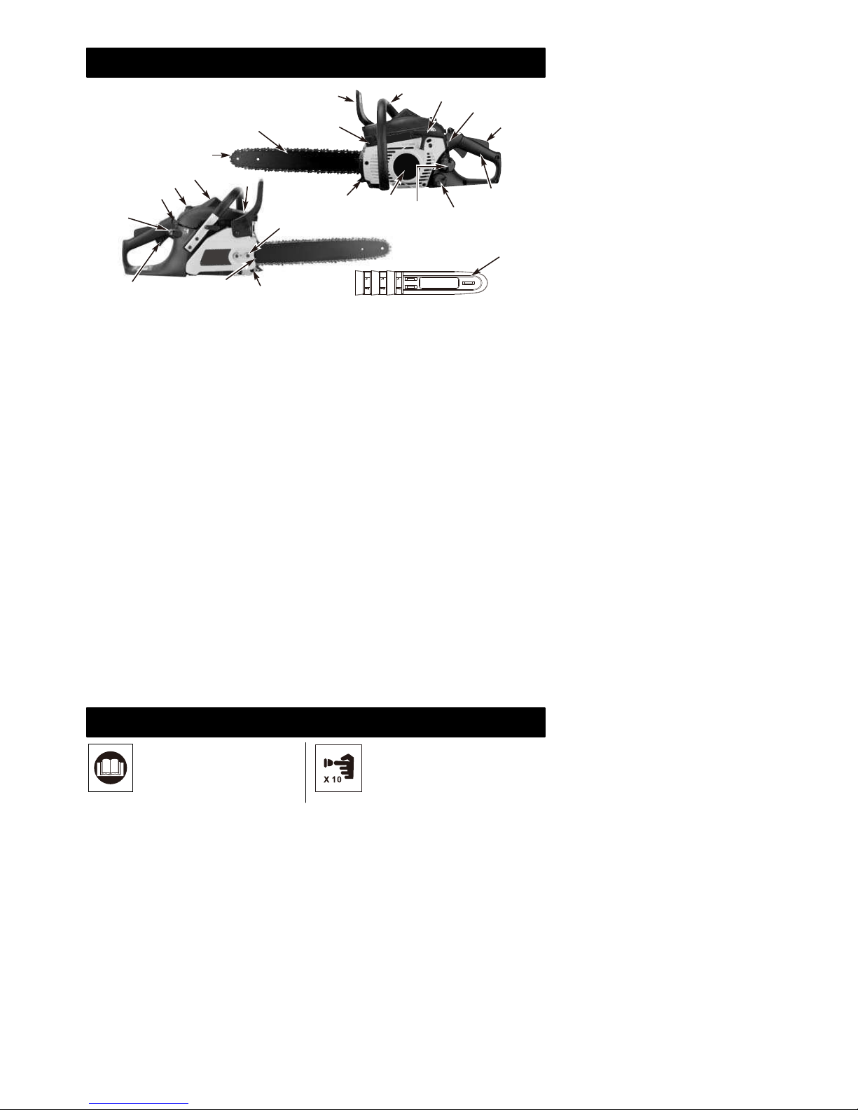
There are 3 parts only, chain, bar and
spark plug, can be replaced by the user
themselves and please use the same type
as showed on the specifications in the
user's manual.
(Type for the plug is NGK CMR7H).
If the other components beyond the prior
parts are defective, then please take your
tools to the nearest Authorized Service
Center for service.
NOTE: This appendix is intended primarily
for the consumer or occasional user. These
models are intended for infrequent use by
homeowners, cottagers, and campers, and
for such general applications as clearing,
pruning, cutting firewood, etc. They are not
intended for prolonged use. If the intended
use involves prolonged periods of opera-
tion, this may cause circulatory problems in
the user’s hands due to vibration.
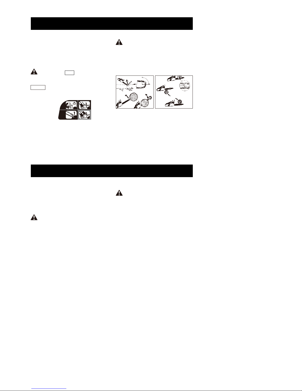
KICKBACK may occur when the NOSE or
TIP of the guide bar touches an object, or
when wood closes in and pinches the saw
chain in the cut.
Tip contact in some cases may cause a
lightning-fast reverse reaction, kicking the
guide bar up and back toward the operator.
PINCHING the saw chain along the
BOTTOM of the guide bar may PULL the
saw forward away from the operator.
PINCHING the saw chain along the TOP of
the guide bar may PUSH the guide bar
rapidly back toward the operator.
Any of these reactions may cause you to
lose control of the saw, which could result in
serious personal injury.
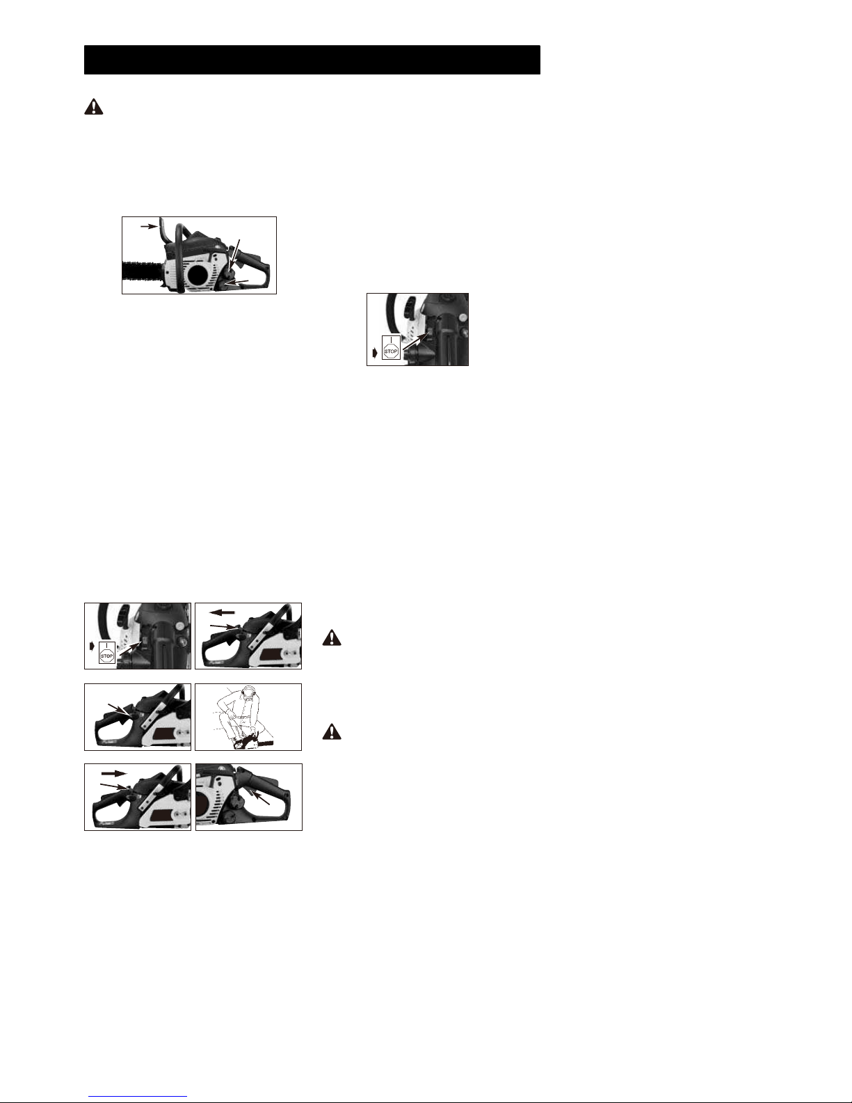
KICKBACK SAFETY PRECAUTIONS
1. With a basic understanding of kickback,
you can reduce or eliminate the element
of surprise.Sudden surprise contributes
to accidents.
2. Keep a good firm grip on the saw with
both hands, the right hand on the rear
handle, and the left hand on the front
handle, when the engine is running. Use
a firm grip with thumbs and fingers
encircling the chain saw handles. A firm
grip will help you reduce kickback and
maintain control of the saw. Don’t let go.
3. Make sure that the area in which you are
cutting is free from obstructions. Do not
let the nose of the guide bar contact a
log, branch, or any other obstruction
which could be hit while you are
operating the saw.
4. Cut at high engine speeds.
5. Do not overreach or cut above shoulder
height.
6. Follow manufacturer’s sharpening and
maintenance instructions for the saw
chain.
7. Only use replacement bars and chains
specified by the manufacturer or the
equivalent.
NOTE: Low-kickback saw chain is chain
that has met the kickback performance.

-- 5 --
WARNING:
Kickback can lead to
dangerous loss of control of the chain saw
and result in serious or fatal injury to the
saw operator or to anyone standing close
by. Always be alert. Rotational kickback
and pinch-kickback are major chain saw
operational dangers and the leading cause
of most accidents.
Your Chain Saw is provided with a safety
label located on the chain brake lever/hand
guard.This label, along with the safety
instructions on these pages, should be
carefully read before attempting to operate
this unit.
IMPORTANT SAFETY
ASSEMBLY INSTRUCTIONS
WARNING: RED Used to warn that
an unsafe procedure should not be
performed.
WARNING: DO NOT start saw
engine until unit is properly prepared.
WARNING: Always wear protective
gloves when handling chain.
HOW TO READ SYMBOLS AND
COLORS (FIG.1)
WARNING
1. Beware of kickback.
2. Do not attempt to hold saw with one
hand.
3. Avoid bar nose contact.
RECOMMENDED
4. Hold saw properly with both hands.
You will need these tools to assemble your
chain saw:
1. Combination wrench-screwdriver (cont-
ained in your user’s kit).
2. Heavy duty work gloves (user supplied). TO INSTALL GUIDE BAR:
To ensure the bar and chain receive oil,
ONLY USE THE ORIGINAL STYLE BAR
with the oil passage hole (A) as illustrated
above. (Fig.3A)
1. Make sure the CHAIN BRAKE lever is
pulled back into the DISENGAGED
position (Fig. 3B)
2. Remove the bar retaining nut
(B). Remove the CHAIN BRAKE cover
(C) by pulling straight out, some force
may be required. (Fig.3C).
Note: Discard the two plastic washers.They
are only used for shipping the chain saw.
3. Using a screwdriver, turn the adjustm-
ent screw (D) COUNTERCLOCKWISE
until theTANG (E) (projecting prong) is to
the end of its travel (Fig. 3D).
4. Place the slotted end of the guide bar
over the bar bolt (F). Slide guide bar
behind clutch drum (G) until the guide
bar stops (Fig.3E).
Your new chain saw will require adjustment
of chain, filling the fuel tank with correct fuel
mixtureandfillingtheoiltank with lubricating
oil before the unit is ready for operation.
Read the entire user manual before
attempting to operate your unit. Pay
particular attention to all safety
precautions.
Your user manual is both a reference guide
and handbook provided to furnish you
with general information to assemble,
operate and maintain your saw.
GREEN RECOMMENDED
Recommended cutting procedure.
1 2
3 4
Fig. 1
DANGER! BEWARE OF KICKBACK!
Fig. 2A
AA
B
A
A
B
C
Fig. 2B
BEWARE OF:
ROTATIONAL
KICKBACK
(Fig. 2A)
A = Kickback path
B = Kickback
reaction zone
THE PUSH (PINCH
KICKBACK) AND
PULL REACTIONS
(Fig. 2B)
A = Pull
B = Solid objects
C = Push
TOOLS FOR ASSEMBLY
ASSEMBLY REQUIREMENTS
GUIDE BAR / SAW CHAIN / CLUTCH
COVER INSTALLATION

-- 6 --
Proper tension of saw chain is extremely
important and must be checked before
starting, as well as during any cutting
operation.
WARNING:Always wear heavy duty
gloves when handling saw chain or making
saw chain adjustments.
CAUTION: A new saw chain
stretches, requiring adjustment after as
few as 5 cuts. This is normal with a new
chain, and the interval between future
adjustments will lengthen quickly.
CAUTION: If saw chain is TOO
LOOSE or TOO TIGHT, the sprocket, bar,
chain, and crankshaft bearings will wear
more rapidly. Study Fig. 6 for information
concerning correct cold tension (A),
correct warm tension (B),andasaguide for
when saw chain needs adjustment (C).
Always wear heavy duty gloves when
handling saw chain or making saw chain
adjustments.
1. Spread chain out in a loop with cutting
edges (A) pointing CLOCKWISE around
loop (Fig. 4A).
2. Slip the chain around the sprocket (B)
behind the clutch (C). Make sure the
links fit between the sprocket teeth
(Fig. 4B).
3. Guide the drive links into the groove (D)
and around the end of the bar (Fig. 4B).
NOTE: The saw chain may droop slightly on
the lower part of bar.This is normal.
4. Pull guide bar forward until chain is
snug. Ensure all drive links are in the bar
groove.
5. Install the clutch cover making sure the
tang is positioned in the lower hole in the
guide bar.Make sure the chain does not
slip off of the bar. Install the bar retaining
nut hand tight and follow tension
adjustment instructions in Section
SAW CHAIN TENSION
ADJUSTMENT.
NOTE: The guide bar retaining nuts are
installed only hand tight at this point
because saw chain adjustment is
required. Follow instructions in Section
SAW CHAIN TENSION ADJUSTMENT.
1. Hold nose of guide bar up and turn
adjustment screw (A) CLOCKWISE to
increase chain tension. Turning screw
COUNTERCLOCKWISE will decrease
amount of tension on chain. Ensure the
chain fits snugly all the way around the
guide bar (Fig. 5).
2. After making adjustment, and while still
holding nose of bar in the uppermost
position, tighten the bar retaining nuts
securely. Chain has proper tension
when it has a snug fit all around and
can be pulled around by gloved hand.
NOTE: If chain is difficult to rotate on
guide bar or if it binds, too much tension
has been applied. This requires minor
adjustment as follows:
A. Loosen the bar retaining nuts so they
are finger tight. Decrease tension by
turning the bar adjustment screw
COUNTERCLOCKWISE slowly. Move
chain back and forth on bar. Continue to
adjust until chain rotates freely, but fits
snugly. Increase tension by turning bar
adjustment screw CLOCKWISE.
B. When saw chain has proper tension,
hold nose of bar in the uppermost
position and tighten the 2 bar retaining
nuts securely.
Fig. 3A
A
Fig. 3B
Fig. 3C
B
Fig. 3D
C
D
E
Fig. 3E
F
G
TO INSTALL SAW CHAIN:
SAW CHAIN TENSION ADJUSTMENT
Taking the time to make needed
adjustments to the saw chain will result in
improved cutting performance and
prolonged chain life.
TO ADJUST SAW CHAIN:
Fig. 4A
A
Fig. 4B
D
B
C
Fig. 5
A
Fig. 6
ACB

-- 7 --
FUEL AND LUBRICATION
WARNING:The purpose of the
chain brake is to reduce the possibility of
injury due to kickback; however, it cannot
provide the intended measure of protection
if the saw is operated carelessly. Always
test the chain brake before using your saw
and periodically while on the job.
Your chain saw is equipped with a Chain
brake that reduces possibility of injury due to
kickback. The brake is activated if pressure
is applied against brake lever when, as in
the event of kickback, operator’s hand
strikes the lever. When the brake is actuated,
chain movement stops abruptly.
WARNING:Never use straight
gasoline in your unit. This will cause
permanent engine damage and void the
manufacturer’s warranty for that product.
Never use a fuel mixture that has been
stored for over 90 days.
Use regular grade unleaded gasoline
mixed with 40:1 custom 2-cycle engine oil
for best results. Use mixing ratios in Section
FUEL MIXINGTABLE.
Some conventional petrols are being
blended with oxygenates such as alcohol or
an ether compound to meet clean air
standards.Yourengine is designed to operate
satisfactorily on any gasoline intended for
automotive use including oxygenated
petrols.
Always refill the chain oil tank each time the
fuel tank is refilled. We recommend using
Partner Chain, Bar and Sprocket Oil, which
contains additives to reduce friction and
wear and to assist in the prevention of pitch
formation on the bar and chain.
Mix fuel with 2 cycle oil in an approved
container. Use mixing table for correct
ratio of fuel to oil. Shake container to
ensure thorough mix.
WARNING:Lack of lubrication voids
engine warranty.
WARNING:If 2-cycle lubricant
other thanCustom Lubricant is to be used, it
must be a premium grade oil for 2-cycle air
cooled engines mixed at a 40:1 ratio.Do not
use any 2-cycle oil product with a
recommended mixing ratio of 100:1. If
insufficient lubrication is the cause of engine
damage, it voids the manufacturer’s engine
warranty for that occurrence.
1. The CHAIN BRAKE is DISENGAGED
(chain can move) when BRAKE LEVER
IS PULLED BACK AND LOCKED. Be
sure the chain brake latch is in the OFF
position. (Fig. 7A)
CHAIN BRAKE MECHANICAL TEST
TO TEST CHAIN BRAKE:
2. The CHAIN BRAKE is ENGAGED (chain
is stopped) when brake lever is in forward
position and the chain brake latch is in
the ON position. You should not be able
to move chain. (Fig. 7B)
NOTE:The brake lever should snap into both
positions. If strong resistance is felt, or lever
does not move into either position, do not use
your saw. Take it immediately to a
professional Service Center for repair.
Fig. 7A Fig. 7B
OFF ON
FUEL
MIXING FUEL
FUEL AND LUBRICATION
Gasoline and Oil
Mix 40:1 Oil Only
FUEL MIXING TABLE
RECOMMENDED FUELS
CHAIN AND BAR LUBRICATION
GASOLINE 40:1 Ratio
Custom Lubricant
1 U.S. Gal. 3.2 oz. 95ml (cc)
5 Liters 4.3 oz. 125ml (cc)
4.3 oz. 125ml (cc)
1 lmp. Gal.
Mixing 40 Parts Gasoline
Procedure to 1 part Lubricant
1ml = 1cc

-- 8 --
1.Fill the fuel tank (A) with correct fuel
mixture. (Fig. 8).
2.Fill the oil tank (B) with correct chain and
bar oil (Fig. 8).
3.Be certain the chain brake is disengaged
(C) before starting unit (Fig. 8).
1.Make sure the on/off switch is in the “I”
position.
2. Depress the primer bulb 10 times.
3.Pull the starter rope rapidly 4
times. The engine should start.
4.If the engine still can not start, follow the
step as “To start engine” in this user
manual.
1.Release trigger and allow engine to
return to idle speed.
2.Press STOP switch down to stop engine
Figure 9G.
NOTE: For emergency stopping, simply
activate CHAIN BRAKEand move
STOP switch down.
1.Place saw on a clear, firm, flat surface.
2.Start engine.
3.Grasp the rear handle (A) with your right
hand (Fig. 10).
4.With your left hand, hold the front
handle (B) [not CHAIN BRAKElever (C)]
firmly (Fig. 10).
5.Squeeze the throttle trigger to 1/3 throttle,
then immediately activate the CHAIN
BRAKElever (C) (Fig. 10).
6.Chain should stop abruptly.When it does,
immediately release the throttle trigger.
7.If chain brake functions properly, turn the
engine off and return the chain brake to
the DISENGAGED position.
Test the CHAIN BRAKE periodically to
ensure proper function.
Perform a CHAIN BRAKE test prior to initial
cutting, following extensive cutting, and
definitely following any CHAIN BRAKE
service.
1.Move ON/OFF switch to ON “I”
position. (Fig. 9A)
2.Pull choke lever/throttle (A) advance.This
sets choke and advances throttle for
easier starting. (Fig. 9B)
3.Press primer bulb (B) 10 times. (Fig. 9C)
4.With saw on ground, grip front handle
firmly with left hand and place right foot
inside rear handle. Pull starter rope 4
times with right hand. (Fig. 9D)
NOTE: If the engine sounds as if it wants
to start before the 4th pull, end the tugging
of the starter and proceed as described in
the next step.
5.Push choke lever (C) in
completely. (Fig. 9E)
6.Pull starter rope quickly until engine
starts.
7.Allow the engine to run for about 10
seconds. Squeeze and release throttle
trigger (D) to idle engine. (Fig. 9F)
8.If the eingine does not start up, repeat
the above steps.
OPERATION
ENGINE PRE-START CHECKS
WARNING: Never start or operate
the saw unless the bar and chain are
properlyinstalled.
WARNING: Activate the chain brake
slowly and deliberately. Keep the chain
from touching anything; don t let the saw tip
forward.
WARNING: If chain does not
stop, turn engine off and take your unit to
the nearest Authorized Service Center for
service.
Fig. 8
B
A
C
TO START ENGINE
Fig. 9A Fig. 9B
A
Fig. 9C Fig. 9D
B
Fig. 9E Fig. 9F
D
C
RE-STARTING A WARM ENGINE
TO STOP ENGINE
Fig. 9G
CHAIN BRAKE OPERATIONAL TEST
TEST CHAIN BRAKEAS FOLLOWS:

-- 9 --
GENERAL CUTTING INSTRUCTIONS
Adequate lubrication of the saw chain is
essential at all times to minimize friction with
the guide bar.
Never starve the bar and chain of oil.
Running the saw with too little oil will
decrease cutting efficiency, shorten saw
chain life, cause rapid dulling of chain, and
cause excessive wear of bar from
overheating. Too little oil is evidenced by
smoke, bar discoloration or pitch build-up.
NOTE: Saw chain stretches during use,
particularly when it is new, and it will
Your chain saw is equipped with an
automatic clutch driven oiler system. The
oiler automatically delivers the proper
amount of oil to the bar and chain. As the
engine speed increases, so does the oil flow
to the bar pad. There is no flow adjustment.
The oil reservoir will run out at approximately
the same time as the fuel supply runs out.
WARNING: Don't put pressure on
the saw when reaching the end of the cut.
The pressure may cause the bar and chain
to rotate. If the rotating chain strikes some
other object, a reactive force may cause
moving chain to strike the operator.
Felling is the term for cutting down a tree.
Small trees up to 6-7 inches (15-18cm) in
diameter are usually cut in a single cut.
Larger trees require notch cuts. Notch cuts
determine the direction the tree will fall.
Normally felling consists of 2 main cutting
operations, notching (C) and making the
felling cut (D).
Start making the upper notch cut (C) on the
side of the tree facing the felling direction
(E). Be sure you don t make the lower cut
too deep into the trunk.
The notch (C) should be deep enough to
create a hinge (F) of sufficient width and
strength. The notch should be wide enough
to direct the fall of the tree for as long as
possible.
NOTE:Direction of fall (B) is controlled by the
notching cut. Before any cuts are made,
consider the location of larger branches and
natural lean of the tree to determine the way
the tree will fall.
WARNING: A retreat path (A) should
be planned and cleared as necessary before
cuts are started. The retreat path should
extend back and diagonally to the rear of the
expected line of fall, as illustrated in
Fig.11A. WARNING: Never walk in front of a
tree that has been notched.
Make the felling cut (D) from the other side of
the tree and 1.5 - 2.0 inches (3-5 cm) above
the edge of the notch (C) (Fig.11B)
Never saw completely through the trunk.
Always leave a hinge. The hinge guides the
tree. If the trunk is completely cut through,
control over the felling direction is lost.
Insert a wedge or felling lever in the cut well
before the tree becomes unstable and starts
to move. This will prevent the guidebar from
binding in the felling cut if you have
misjudged the falling direction. Make sure no
bystanders have entered the range of the
falling tree before you push it over.
WARNING: Do not cut down a tree
during high or changing winds or if there is a
danger to property. Consult a tree
professional. Do not cut down a tree if there
is a danger of striking utility wires; notify the
utility company before making any cuts.
CAUTION: If felling a tree on sloping
ground, the chain saw operator should keep
on the uphill side of the terrain, as the tree is
likely to roll or slide downhill after it is felled.
Fig. 10
ABC
SAW CHAIN / BAR LUBRICATION
AUTOMATIC OILER
occasionally be necessary to adjust and
tighten it. New chain will require adjustment
after about 5 minutes of operation.
FELLING
FELLING A TREE:
Fig. 11A
B
A
GENERAL GUIDELINES FOR FELLING
TREES:
Fig. 11B

-- 10 --
FELLING CUT:
WARNING: Before making the final
cut, always recheck the area for bystanders,
animals or obstacles. Bucking is cutting a fallen log into lengths.
Make sure you have a good footing and
stand uphill of the log when cutting on
sloping ground. If possible, the log should
be supported so that the end to be cut off is
not resting on the ground. If the log is
supported at both ends and you must cut in
the middle, make a downward cut halfway
through the log and then make the
undercut. This will prevent the log from
pinching the bar and chain. Be careful that
the chain does not cut into the ground when
bucking as this causes rapid dulling of the
chain.
When bucking on a slope, always stand on
the uphill side.
1.Use wooden or plastic wedges (G) to
prevent binding the bar or chain (H) in the
cut. Wedges also control felling
(Fig.11C).
2.When diameter of wood being cut is
greater than the bar length, make 2 cuts
as shown (Fig.11D).
1.Log supported along entire length: Cut
from top (overbuck), being careful to
avoid cutting into the ground (Fig. 13A).
2.Log supported on 1 end: First, cut from
bottom (underbuck) 1/3 diameter of log to
avoid splintering. Second, cut from above
(overbuck) to meet first cut and avoid
pinching (Fig. 13B).
3.Log supported on both ends: First,
overbuck 1/3 diameter of log to avoid
splintering. Second, underbuck to meet
first cut and avoid pinching (Fig. 13C).
NOTE: The best way to hold a log while
bucking is to use a sawhorse. When this is
not possible, the log should be raised and
supported by the limb stumps or by using
supporting logs. Be sure the log being cut is
securely supported.
A.Hold the saw firmly with both hands and
keep the saw to the right of your body
while cutting.
B.Keep the left arm as straight as possible.
C.Keep weight on both feet.
Limbing a tree is the process of removing
the branches from a fallen tree. Do not
remove supporting limbs (A) until after the
log is bucked (cut) into lengths (Fig.12).
Branches under tension should be cut from
the bottom up to avoid binding the chain
saw.
For personal safety and ease of cutting, the
correct position for vertical bucking is
essential (Fig.14).
WARNING: As the felling cut gets
close to the hinge, the tree should begin to
fall. When tree begins to fall, remove saw
from cut, stop engine, put chain saw down,
and leave area along retreat path (Fig.11A).
WARNING: Never cut tree limbs
while standing on tree trunk.
CAUTION: While the saw is cutting,
be sure the chain and bar are being properly
lubricated.
Fig. 11DFig. 11C
AB
LIMBING
Fig. 12
Fig. 13B
Fig. 13A
Fig. 13C
BUCKING
BUCKING USING A SAWHORSE
VERTICAL CUTTING:
Fig. 14
B
A
C600mm

-- 11 --
MAINTENANCE INSTRUCTIONS
All chain saw service, other than items listed
here in your user manual maintenance
instructions, should be performed by a
professional.
A good preventive maintenance program of
regular inspection and care will increase life
and improve performance of your chain saw.
This maintenance checklist is a guide for
such a program.
Cleaning, adjustment, and parts replacement
may be required, under certain conditions, at
more frequent intervals than those indicated.
1.Remove knob (A) holding air filter cover in
place, remove the top cover (B) by
loosening the cover retaining screws.
Cover will lift off. (Fig.15A)
2.Lift the air filter (C) out of air-box (D)
(Fig.15B).
3.Clean air filter. Wash filter in clean, warm,
soapy water. Rinse in clear, cool water. Air
dry completely.
NOTE: It is advisable to have a supply of
spare filters.
4.Install air filter. Install engine / air filter
cover. Make sure latche (E) latch (F) and
cover fit properly. Tighten the cover
retaining knob securely. (Fig.15C &
Fig.15D)
1.Remove the fuel tank cap.
2.Bend a piece of soft wire to from a hook at
the end.
3.Reach into fuel tank opening and hook fuel
line. Carefully pull the fuel line toward the
opening until you can reach it with your
fingers.
NOTE: Do not pull hose completely out of
tank.
4.Lift filter (A) out of tank (Fig.16).
5.Pull filter off with a twisting motion. Discard
filter.
6.Install new filter. Insert end of filter into
tank opening. Make sure filter sits in
bottom corner of tank. Use a long
screwdriver to aid in filter placement if
necessary.
7.Fill tank with fresh fuel / oil mixture. See
Section FUEL AND LUBRICATION.
Install fuel cap.
1.Remove the 2 bolts (A) and pull muffler
out. (Fig. 17A).
2.Remove the 2 screws that holds the cover
(C). (Fig.17B)
3.Discard the used spark arrester screen (D)
andreplace it with a new one.
4.Reasemble the muffler components and
install the muffler to the cylinder. Tighten
securely.
WARNING: Never perform mainten-
ance when the engine is hot, to avoid any
chance of burning hands or fingers.
NOTE: A clogged spark arrester screen will
dramatically reduce engine performance.
WARNING: Never operate your saw
without a fuel filter. The fuel filter should be
replaced after each 20 hours of use. Drain
fuel tank completely before changing filter.
CAUTION: Never operate saw
without the air filter. Dust and dirt will be
drawn into engine and damage it. Keep the
air filter clean!
PREVENTIVE MAINTENANCE
AIR FILTER
TO CLEAN AIR FILTER:
Fig. 15A
A
Fig. 15B
C
D
B
Fig. 15C
E
Fig. 15D
FF
B
FUEL FILTER
Fig. 16
A
SPARK ARRESTER SCREEN
HOURS OF
EACH
MAINTENANCE
CHECKLIST USE OPERATION
ITEM ACTION
Screws/Nuts/Bolts Inspect/Tighten
Air Filter Clean or Replace
Fuel Filter/Oil Filter Replace
Spark Plug Clean/Adjust/Replace
Spark Arrester Screen Inspect
Fuel Hoses Inspect
10 20
Replace as Required
Replace as Required
Chain brake Inspect
componentsReplace as Required

-- 12 --
NOTE: For efficient operation of saw engine,
spark plug must be kept clean and properly
gapped.
1.Push STOP switch down.
2.Remove knob (A) holding air filter cover in
place, remove the top cover (B) by
loosening the cover retaining screws.
Cover will lift off. (Fig.18A)
3.Disconnect the wire connector (C) from the
spark plug (D) by pulling and twisting at the
same time (Fig. 18B).
4.Remove spark plug with spark plug socket
wrench. DO NOT USE ANY OTHER
TOOL.
5.Check electtrode gaps with wire feeler
gauge and set gaps to .025” (.635mm) if
necessary.
6.Reinstall a new spark plug.
NOTE: A resistor spark plug must be used for
replacement.
NOTE: This spark ignition system meets all
requirements of the Interference-Causing
Equipment Regulations.
1.Remove spark plug.
2.Pull starter rope briskly to clear excess oil
from combustion chamber.
3.Clean and gap spark plug or install a new
spark plug with proper gap.
4.Prepare unit for operation.
5.Fill fuel tank with proper fuel / oil mixture.
See FUEL AND LUBRICATION Section.
Frequent lubrication of the guide bar (railed
bar which supports and carries the saw
chain) sprocket tip is required. Proper
maintenance of the guide bar, as explained in
this section, is essential to keep your saw in
good working condition.
Lubrication of the sprocket tip is
recommended after 10 hours of use or once
a week, which ever occurs first. Always
thoroughly clean guide bar sprocket tip
before lubrication.
The Lube Gun (optional) is recommended for
applying grease to the guide bar sprocket tip.
The Lube Gun is equipped with a needle
nose tip which is necessary for the efficient
application of grease to the sprocket tip.
Storing a chain saw for longer than 30 days
requires storage maintenance. Unless the
storage instructions are followed, fuel
remaining in the carburetor will evaporate,
leaving gum-like deposits. This could lead to
difficult starting and result in costly repairs.
1.Remove the fuel tank cap slowly to release
any pressure in tank. Carefully drain the
fuel tank.
2.Start the engine and let it run until the unit
stops to remove fuel from carburetor.
3.Allow the engine to cool (approx. 5
minutes).
4.Using a spark plug wrench, remove the
spark plug.
1.Press the STOP switch down.
NOTE: It is not necessary to remove the saw
chain to lubricate the guide bar sprocket tip.
Lubrication can be done on the job.
2.Clean the guide bar sprocket tip.
3.Using the Lube Gun (optional), insert
needle nose into the lubrication hole and
inject grease until it appears at outside
edge of sprocket tip (Fig. 20).
CAUTION: Never store a chain saw
for longer than 30 days without performing
the following procedures.
The carburetor was preset at the factory for
optimum performance. If further adjustments
are necessary, please take your unit to the
nearest qualified service technician.
WARNING: Wear heavy duty work
gloves when handling the bar and chain.
CAUTION: The sprocket tip on your
new saw has been pre-lubricated at the
factory. Failure to lubricate the guide bar
sprocket tip as explained below will result in
poor performance and seizure, voiding the
manufacturer’s warranty.
Fig. 17A
A
Fig. 17B
BC
B
B
D
SPARK PLUG
Fig. 18A
A
Fig. 18B
C
D
B
CARBURETOR ADJUSTMENT
STORING A CHAIN SAW
5.Pour 1 teaspoon of clean 2-cycle oil into
the combustion chamber. Pull starter rope
slowly several times to coat internal
components. Replace spark plug. (Fig. 19)
NOTE: Store the unit in a dry place and away
from possible sources of ignition such as a
furnace, gas hot water heater, gas dryer, etc.
Fig. 19
REMOVING A UNIT FROM STORAGE
GUIDE BAR MAINTENANCE
SPROCKET TIP LUBRICATION:
TOOLS FOR LUBRICATION:
TO LUBRICATE SPROCKET TIP:

-- 13 --
WARNING: Always wear protective
gloves during maintenance operations. Do
not carry out maintenance when the engine is
hot.
WARNING: After 3 to 4 of your
sharpening of the cutting teeth, have the saw
chain sharpened in any authorised service.
They will sharpen the depth limiter as well,
which provides the distance.
CHAIN SHARPENING - The pitch of the
chain (Fig. 21) is 3/8” LoPro x .050”.
Sharpen the chain using protective gloves
and a round file of ø5/32” (4mm).
Always sharpen the cutters only with outward
strokes (Fig. 22) observing the values given
in Fig. 21.
After sharpening, the cutting links must all
have the same width and length.
WARNING: A sharp chain produces
welldefined chips. When your chain starts to
produce sawdust, it is time to sharpen.
After every 3-4 times the cutters have been
sharpened you need to check the height of
the depth gauges and, if necessary, lower
them using the flat file and template supplied
optional, then round off the front corner.
(Fig. 23)
WARNING: Proper adjustment of the
depth gauge is as important as proper
sharpening of the chain.
WARNING: Never mount a new
chain on a worn sprocket or self-aligning ring.
WARNING: When having wrong
sharpened chain, there may occur a higher
danger of kickback.
WARNING: All cutting teeth must be
similarly long. Different length of the teeth
can cause rough run of the chain or its
rupture, as well.
4.Rotate saw chain by hand. Repeat
lubrication procedure until the entire
sprocket tip has been greased.
1.To sharpen the saw chain, use the suitable
sharpen-ing tools:
- Round chain file ø5/32”(4mm).
- File leading
- Chain measuring calibre.
These tools can be bought in any
specialsed stores.
2. To gain well shaped sawdust particles, use
sharp chain. If there appears wooden
powder, you must sharpen the saw chain.
GUIDE BAR- The bar should be reversed
every 8 working hours to ensure uniform
wear.
Keep the bar groove and lubrication hole
clean using a bar groove cleaner (optional).
(Fig. 24)
Check the bar rails frequently for wear and, if
necessary, remove the burs and square-up
the rails using a flat file. (Fig.25)
3.Minimum length of the teeth must be 4mm.
If they are shorter, remove the saw chain.
4.Angles, which the teeth are under, must be
followed.
5.To sharpen the chain basically, make 2 to
3 pulls of the file from the inside out.
Most guide bar problems can be
prevented merely by keeping the chain
saw well maintained.
Insufficient guide bar lubrication and
operating the saw with chain that is TOO
TIGHT will contribute to rapid bar wear.
To help minimize bar wear, the following
guide bar maintenance procedures are
recommended.
Chain sharpening requires special tools to
ensure that cutters are sharpened at the
correct angle and depth. For the
inexperienced chain saw user, we
recommend that the saw chain be
professionally sharpened by the nearest
professional Service Center. If you feel
comfortable sharpening your own saw chain,
special tools are available from the
professional Service Center. For
non-experienced users of the chain saw, we
recommend to have the chain sharpened by
a specialist in any authorised service.
Fig. 20
GUIDE BAR MAINTENANCE:
CHAIN SHARPENING:
Fig. 21
Fig. 22 Fig. 23
Fig. 24 Fig. 25

-- 14 --
WARNING: Alwaysstopunitanddisconnectsparkplugbeforeperformingallofthe
recommended remediesbelow except remediesthat require operation of theunit.
TROUBLESHOOTING TABLE
CHAIN MAINTENANCE
BREAKING IN A NEW SAW CHAIN:
CHAIN LUBRICATION:
BAR WEAR - Turn guide bar frequently at
regular intervals (for example, after 5
hours of use), to ensure even wear on top
and bottom of bar.
OIL PASSAGES - Oil passages on the bar
should be cleaned to ensure proper
lubrication of the bar and chain during
operation.
NOTE: The condition of the oil passages
can be easily checked. If the passages are
clear, the chain will automatically give off a
spray of oil within seconds of starting the
saw. Your saw is equipped with an
automatic oiler system.
CHAIN TENSION:
Check the chain tension frequently and
adjust as often as necessary to keep the
chain snug on the bar, but loose enough to
be pulled around by hand.
A new chain and bar will need chain
readjustment after as few as 5 cuts. This is
normal during the break-in period, and the
interval between future adjustments will
begin to lengthen quickly.
WARNING:Never have more than 3
links removed from a loop of chain. This
could cause damage to the sprocket.
Always make sure the automatic oiler
system is working properly. Keep the oil
tank filled with Chain, Bar and Sprocket Oil.
Adequate lubrication of the bar and chain
during cutting operations is essential to
minimize friction with the guide bar.
Never starve the bar and chain of lubricating
oil. Running the saw dry or with too little oil
will decrease cutting efficiency, shorten saw
chain life, cause rapid dulling of chain, and
lead to excessive wear of bar from
overheating. Too little oil is evidenced by
smoke or bar discoloration.
PROBLEM
Unit won’t start or starts
but will not run.
Unit starts, but engine
has low power.
Engine hesitates.
No power under load.
Runs erratically.
Smokes excessively.
PROBABLE CAUSE
Incorrect starting procedures.
Incorrect carburetor mixture
adjustment setting.
Incorrect carburetor mixture
adjustment setting.
Incorrect carburetor mixture
adjustment setting.
Incorrect carburetor mixture
adjustment setting.
Fouled spark plug
Fuel filter plugged.
Dirty spark arrester screen.
Dirty air filter.
Incorrectly gapped spark plug.
Incorrect fuel mixture.
CORRECTIVE ACTION
Follow instructions in the User Manual.
Have carburetor adjusted by an Authorized
Service Center.
Have carburetor adjusted by an Authorized
Service Center.
Have carburetor adjusted by an Authorized
Service Center.
Have carburetor adjusted by an Authorized
Service Center.
Clean / gap or replace plug.
Replace fuel filter.
Replace spark arrester screen.
Remove, clean and reinstall filter.
Clean / gap or replace plug.
Use properly mixed fuel (40:1 mixture).

-- 15 --
DECLARATION OF CONFORMITY
Business name of the manufacturer: Husqvarna AB
Full address of the manufacturer: SE-561 82 Huskvarna, Sweden
We declaring that the machinery
Product name: Chain saw
Commercial name: Petrol chain saw
Function: Service for Forest
Model: P340S
Type: Gasoline powered
Serial number: 11001S100001~21365S999999
Fulfils all the relevant provisions of Directives
2006/42/EC, 2004/108/EC, 2000/14/EC+2005/88/EC
Based on EC type-examination of
Name, address and identification number of the notified body:
TÜV Reinland LGA Products GmbH
Tillystrasse 2,90431, Nuremberg
Number of the EC ty
pe-examination certificate:
BM 50215796
and tested in accordance with below standards
EN ISO 11681-1:2008
EN ISO 14982:2009
Person authorised to compile the technical file and making
this declaration:
Name, surname : Bo R Jonsson
Position/Title : R&D Manager
Address : SE-561 82 Huskvarna, Sweden
Place and date of the declaration: Shanghai, PRC 2011/12/20

-- 16 --
TECHNICAL DATA SHEET
Model No. . . . . . . . . . . . . . . . . . . . . . . . . . . . . . . . . . . . . . . . . . . . . . . . . . . . P340S
Rated Net Power . . . . . . . . . . . . . . . . . . . . . . . . . . . . . . . . . . . . . . . . . . . . . . . . . . . . . . 1.44 kW
The Usable Cutting Lengths . . . . . . . . . . . . . . . . . . . . . . . . . . . . . . . . . . . . . . . . . . . . . . 33cm
Bar Cutting Length . . . . . . . . . . . . . . . . . . . . . . . . . . . . . . . . . . . . . . . . . . . . . . . . . . . . . 35cm
Chain Pitch . . . . . . . . . . . . . . . . . . . . . . . . . . . . . . . . . . . . . . . . . . . . . . . . . . . . . . . . . . 9,53mm (3/8”)
Chain Gauge . . . . . . . . . . . . . . . . . . . . . . . . . . . . . . . . . . . . . . . . . . . . . . . . . . . . . . . . . . 1.27mm (0.05”)
Idle Speed (Max.) . . . . . . . . . . . . . . . . . . . . . . . . . . . . . . . . . . . . . . . . . . . . . . . . . . . . . 3300 min-1
Recommended maximum speed
with cutting attchment . . . . . . . . . . . . . . . . . . . . . . . . . . . . . . . . . . . . . . . . . . . . . . . . . . 13500 min-1
Fuel Capacity . . . . . . . . . . . . . . . . . . . . . . . . . . . . . . . . . . . . . . . . . . . . . . . . . . . . . . . . . 250 cm3
Oil Capacity . . . . . . . . . . . . . . . . . . . . . . . . . . . . . . . . . . . . . . . . . . . . . . . . . . . . . . . . . . 150 cm3
Anti Vibration . . . . . . . . . . . . . . . . . . . . . . . . . . . . . . . . . . . . . . . . . . . . . . . . . . . . . . . . . Yes
Drive Sprocket . . . . . . . . . . . . . . . . . . . . . . . . . . . . . . . . . . . . . . . . . . . . . . . . . . . . . . . . 6 Teeth
Easy Start . . . . . . . . . . . . . . . . . . . . . . . . . . . . . . . . . . . . . . . . . . . . . . . . . . . . . . . . . . . . No
Auto Choke . . . . . . . . . . . . . . . . . . . . . . . . . . . . . . . . . . . . . . . . . . . . . . . . . . . . . . . . . . . Yes
Chain Brake . . . . . . . . . . . . . . . . . . . . . . . . . . . . . . . . . . . . . . . . . . . . . . . . . . . . . . . . . . Yes
Clutch . . . . . . . . . . . . . . . . . . . . . . . . . . . . . . . . . . . . . . . . . . . . . . . . . . . . . . . . . . . . . . Yes
Automatic Chain Oiler . . . . . . . . . . . . . . . . . . . . . . . . . . . . . . . . . . . . . . . . . . . . . . . . . . Yes
Low Kick-back Chain Type (Oregon) . . . . . . . . . . . . . . . . . . . . . . . . . . . . . . . . . . . . . . 91PJ052X
Type of Guide Bar (Oregon) . . . . . . . . . . . . . . . . . . . . . . . . . . . . . . . . . . . . . . 140SDEA041
Low Kick-back Chain Type (Carlton) . . . . . . . . . . . . . . . . . . . . . . . . . . . . . . . . . . . . . .
N1C-BL-M-52E SK
Type of Guide Bar (Carlton) . . . . . . . . . . . . . . . . . . . . . . . . . . . . . . . . . . . . . . .14-10-N1-MHC
Net Weight (Without guide bar and chain) . . . . . . . . . . . . . . . . . . . . . . . . . . . . . . . . . . 4.5 Kg
Sound pressure level at ear (EN ISO 11681-1)(K=1.5) . . . . . . . . . . . . . . . . . . . . . . . . . .103 dB(A)
Sound power level (EN ISO 11681-1)(K=1.5) . . . . . . . . . . . . . . . . . . . . . . . . . . . . . . . . 105 dB(A)
Guarantee sound power level
(2000/14/EC+2005/88/EC)
. . . . . . . . . . . . . . . . . . . . . . . . . . 108 dB(A)
Braking Time (Max.) . . . . . . . . . . . . . . . . . . . . . . . . . . . . . . . . . . . . . . . . . . . . . . . . . . . 0.12 s
Vibration Level (Max.) (K=1.5). . . . . . . . . . . . . . . . . . . . . . . . . . . . . . . . . . . . . . . . . . . . 15 m/s2
Fuel Consumption . . . . . . . . . . . . . . . . . . . . . . . . . . . . . . . . . . . . . . . . . . . . . . . . . . . . . 519.3 g/kWh
Engine Displacement . . . . . . . . . . . . . . . . . . . . . . . . . . . . . . . . . . . . . . . . . . . . . . . . . . . 35 cm3(2.1 cu-in)

-- 17 --
.
20
19
18 17 16 15
21 22
14
13
1
7
56
11
2
23
3
4
10
12 9
8
1.
2.
3.
4.
( )
5.
6.
7.
8.
9. (
)
10.
11.
12.
13.
14.
15.
16.
17.
18.
19.
20. ()
21.
22.
23.
( )
– .
1 -
-
.
3
0,6 (0,023
) -
.
,
(),
-
.
.
«
».
4 (
)
.
4 – -
,
.
.
7 «STOP» ()
.
«STOP»
()
«.».
8
. (20) ,
.
22
.
.

-- 18 --
!
.
, –
.
, -
,
-
().
, ,
, ,
.
!
-
(
)
()
.
.
!
-
.
-
.
.
• !
,
.
.
• , -
, -
, .
• , ,
,
.
•
.
3 (10 )
.
•
.
.
• ,
,
.
•
.
• ,
.
•
,
,
.
• ,
,
. ,
.
• ,
.
•
,
.
•
,
.
• ,
.
•
.
. -
.
-
.
,
!
( ).
LWA
2000/14/EC 2005/88/EC
!
.
.
108
Other manuals for P340S
1
Table of contents
Languages:
Other Partner Chainsaw manuals

Partner
Partner 350 User manual

Partner
Partner P820T User manual

Partner
Partner Formula 400 CHROME User manual

Partner
Partner K950 Active User manual

Partner
Partner P360S User manual

Partner
Partner P360S User manual

Partner
Partner P842 User manual

Partner
Partner P350S User manual

Partner
Partner 422 User manual

Partner
Partner 530084168 User manual