Partner 621504x117NA User manual

Instruction Book -Snowthrower Model 621504x117NA
Livret d’instructions -Chasse-neige 621504x117NA
Betriebsanleitung -Schneeschleuder Modell 621504x117NA
Manuale di istruzioni -Spalaneve meccanico modello 621504x117NA
Instructieboek -Sneeuwblazer Model 621504x117NA
Instruktionsbog -Sneslynge model 621504x117NA
Instruksjonsbok -Snøfreser modell 621504x117NA
Instruktionsbok -Snöslunga, modell 621504x117NA
Ohjekirja -Lumilinko malli 621504x117NA
Manual de instrucciones -Quitanieves Modelo 621504x117NA
Kasutusjuhend —Lumekoristaja mudel 621504x117NA
Âéâëßï Ïäçãéþí –Åê÷éïíéóôÞñáò ÌïíôÝëï 621504x117NA
Használati kézikönyv –Hómaró 621504x117NA modell
Lietošanas instrukciju —Sniega pūtējs Modelis 621504x117NA
Instrukcija —Sniego valymo įrengimas Modelis 621504x117NA
Instrukcja –Odœnie¿arka Model 621504x117NA
Uživatelská pøíruèka –Snìžná fréza – model 621504x117NA
Návod na používanie –Snehová fréza, model 621504x117NA
Ðóêîâîäñòâî —Ñíåãîî÷èñòèòåëü, ìîäåëü 621504x117NA
FR
D
I
NL
DK
N
S
SF
GB
ES
EE
GR
H
LV
LT
PL
1740281 TP 199-4408-00-SW-R
CZ
SK
RU

2
1740281
1
1
1
2
2
2
3
5
12
8
15
11
14
12
9
10
4
3
1
2
1
3
4
1
2
11
22
56
5
2
1
3

3
1740281
3
1
7
2
4
5
6
7
8
14
15
16
14
14
14
17
17
12
13
9
2
1
3
1/8” (3mm)
4
5
10
2
1
11
3
44
5
6
12
1
2
3
4
5

4
1740281
13
2
4
1
3/32”
14
1
4
3
2
6
5
15
1
2
3
16 17
1

GB
5
1740281
CONTENTS
HAZARD SYMBOLS AND THE MEANINGS 6..........
OPERATING SYMBOLS AND THEIR MEANINGS 6.....
RULES FOR SAFE OPERATION 7....................
ASSEMBLY 9.......................................
OPERATION 10.....................................
MAINTENANCE 12..................................
MAINTENANCE CHART 12...........................
TROUBLE SHOOTING CHART 14.....................
LIMITED WARRANTY 15.............................
General Information
This instruction book is written for a person with some mechanical ability.
Like most service books, not all the steps are described. Steps on how to
loosen or tighten fasteners are steps anyone can follow with some
mechanical ability. Read and follow these instructions before you use the
unit.
Know your product: If you understand the unit and how the unit
operates, you will get the best performance. As you read this manual,
compare the illustrations to the unit. Learn the location and the function of
the controls. To help prevent an accident, follow the operating instructions
and the safety rules. Keep this manual for future reference.
IMPORTANT: Many units are not assembled and are sold in cartons. It is
the responsibility of the owner to make sure the assembly instructions in
this manual are exactly followed. Other units are purchased in an
assembled condition. On assembled units, it is the responsibility of the
owner to make sure the unit is correctly assembled. The owner must
carefully check the unit according to the instructions in this manual before
it is first used.
Controls & Equipment Features (see Figure 2)
Crank Assembly (2) -- Changes the direction of the discharge chute.
Chute Deflector (3) -- Changes the distance the snow is thrown.
Discharge Chute (4) -- Changes the direction the snow is thrown.
Auger Drive Lever (5) -- Starts and stops the auger (snow gathering and
throwing) which also propels the snowthrower.
Engine Features
Stop Switch (8) -- If equipped, move to the ON position to start the
engine.
Ignition Key (8) -- If equipped, insert and turn to the on position to start
the engine.
Primer Button (9) -- Injects fuel directly into the carburetor for fast starts
in cold weather.
Electric Start Button (10) -- On electric start models, used to start the
engine.
Switch Box (11) -- On electric start models, used to attach a 220 volt
electric power cord.
Recoil Starter Handle (12) -- Use to manually start the engine.
Choke Control (14) -- Use to start a cold engine.
Spark Plug Access Panel (15) -- Remove to access the spark plug.
MODEL NO.: 621504x117NA
SERIAL NO.:
4000 min-1 34 kg
SKU No.:
Assembled in Suzhou, China 215218
by Limac for The Partner Corporation
YYYY MM DD:
Declared vibration emission values in accordance with Directive 98/37/EC.
Vibration Emission according to EN 1033;1996: 12,7 m/s2.
Values determined at the handle when the machine was operated stationary on a
concrete surface at 4000 min--1.
Declared airborne noise emissions of LwA104 dB is in accordance with Directive
2000/14/EC, Annex V.
Sound Pressure Level at operator position 83 dB.
Values determined at ear according to the specifications of EN ISO 11201.
Declared airborne sound
power level of 104 dB(A) is in
accordance with Directive
2000/14/EC.

GB
6
1740281
This manual contains safety information to make you
aware of the hazards and risks associated with snow
throwers, and how to avoid them. The snow thrower is designed and
intended for removal of snow, and should not be used for any other
purpose. It is important that you read and understand these
instructions, and anyone operating the equipment read and understand
these instructions.
The engine exhaust from this product contains chemicals known to the
State of California to cause cancer, birth defects, or other reproductive
harm.
WARNING
A signal word (DANGER, WARNING, or CAUTION) is used with the alert
symbol to indicate the likelihood and the potential severity of injury. In
addition, a hazard symbol may be used to represent the type of hazard.
DANGER indicates a hazard which, if not avoided, will result in
death or serious injury.
WARNING indicates a hazard which, if not avoided, could result
in death or serious injury.
CAUTION indicates a hazard which, if not avoided, might result
in minor or moderate injury.
CAUTION, when used without the alert symbol, indicates a
situation that could result in damage to the equipment.
Hazard Symbols and the meanings
These symbols are used on your equipment and defined in your operating
manual. Review and understand the meanings. The use of one of these
symbols combined with a signal word will alert you to potential hazards
and how to avoid them.
Explosion
Toxic fumes Shock
Hot Surface
Fire
Operator’s Manual -- Read and understand before
performing any activity or running equipment.
Safety Alert -- Identifies safety information about
hazards that can result in personal injury.
Rotating auger
Rotating impeller
Rotating gears
Thrown objects
Keep a safe distance
from the equipment.
Shut off engine and remove spark plug connector
before performing maintenance or repair work.
Never reach into
rotating parts.
Recommended ear
protection for extended
use.
Operating Symbols and their meanings
These symbols are used on your equipment and defined in your operating
manual. It is important that you review and understand the meanings.
Failure to understand the symbols might result in harm to you.
Stop
Fuel
Choke off
Oil
Choke on
Slow
Fast
On Off
Ignition Key
Ignition Off
Ignition On
Primer bulb
Throttle
Drive Clutch
Auger Clutch
Engage
RIGHT
Auger Collector
Traction
Discharge Chute
LEFT UP DOWN
Foward
Neutral
Reverse
Push to engage
electric start
Electric
Start
Engine
Start
Engine Run
Engine Off
Chute Deflector
Engage
Disengage
Heated Grips
Engage

GB
7
1740281
WARNING: This machine is capable ofto amputating hands and feet and throwing objects. Read these safety rules
and follow them closely. Failure to obey these rules could result in loss of control of unit, severe personal injury or
death to you, or bystanders, or damage to property or equipment. The triangle in text signifies important cau-
tions or warnings which must be followed.
Safe Operation Practices for Snowthrowers
IMPORTANT: Safety standards require operator presence controls to
minimize the risk of injury. Your snowthrower is equipped with such con-
trols. Do not attempt to defeat the function of the operator presence con-
trol under any circumstances.
Training
1. Read, understand, and follow all instructions on the machine and in the
manuals before operating this unit. Be thoroughly familiar with the con-
trols and the proper use of the equipment. Know how to stop the unit
and disengage the controls quickly.
2. Never allow children to operate the equipment. Never allow adults to
operate the equipment without proper instruction.
3. Keep the area of operation clear of all persons, particularly small
children and pets.
4. Exercise caution to avoid slipping or falling especially when operating in
reverse.
Preparation
1. Thoroughly inspect the area where the equipment is to be used and
remove all doormats, sleds, boards, wires, and other foreign objects.
2. Disengage all clutches and shift into neutral before starting the engine
(motor).
3. Do not operate the equipment without wearing adequate winter outer
garments. Wear footwear that will improve footing on slippery surfaces.
Avoid loose fitting clothing that can get caught in moving parts.
4. Handle fuel with care; it is highly flammable.
a. Use an approved fuel container.
b. Never add fuel to a running engine or hot engine.
c. Fill fuel tank outdoors with extreme care. Never fill fuel tank indoors.
Replace fuel cap securely and wipe up spilled fuel.
d. Never fill containers inside a vehicle or on a truck or trailer bed with
a plastic liner. Always place containers on the ground, away from
your vehicle, before filling.
e. When practical, remove gas--powered equipment from the truck or
trailer and refuel it on the ground. If this is not possible, then refuel
such on a trailer with a portable container, rather than from a gaso-
line dispenser nozzle.
f. Keep nozzle in contact with the rim of the fuel tank or container
opening at all times, until refueling is complete. Do not use a nozzle
lock--open device.
g. Replace gasoline cap securely and wipe up spilled fuel.
h. If fuel is spilled on clothing, change clothing immediately.
5. Use extension cords and receptacles as specified by the manufactur-
er for all units with electric drive motors or electric starting motors.
6. Adjust the collector housing height to clear gravel or crushed rock
surfaces.
7. Never attempt to make any adjustments while the engine (motor) is
running (except when specifically recommended by manufacturer).
8. Let engine (motor) and snowthrower adjust to outdoor temperatures
before starting to clear snow.
9. Always wear safety glasses or eye shields during operation or while
performing an adjustment or repair to protect eyes from foreign objects
that may be thrown from the machine.
Operation
1. Do not put hands or feet near or under rotating parts. Keep clear of the
discharge opening at all times.
2. Exercise extreme caution when operating on or crossing gravel drives,
walks or roads. Stay alert for hidden hazards or traffic.
3. After striking a foreign object, stop the engine (motor), remove the wire
from the spark plug, disconnect the cord on electric motors, thoroughly
inspect snowthrower for any damage, and repair the damage before
restarting and operating the snowthrower.
4. If the unit should start to vibrate abnormally, stop the engine (motor)
and check immediately for the cause. Vibration is generally a warning
of trouble.
5. Stop the engine (motor) whenever you leave the operating position,
before unclogging the collector/impeller housing or discharge chute and
when making any repairs, adjustments, or inspections.
6. When cleaning, repairing, or inspecting, make certain the collector/im-
peller and all moving parts have stopped. Disconnect the spark plug
wire and keep the wire away from the spark plug to prevent accidental
starting.
7. Do not run the engine indoors, except when starting the engine and for
transporting the snowthrower in or out of the building. Open the outside
doors; exhaust fumes are dangerous (containing CARBON MONOX-
IDE, an ODORLESS and DEADLY GAS).
8. Exercise extreme caution when operating on slopes. Do not attempt to
clear steep slopes.
9. Never operate the snowthrower without proper guards, plates, or other
safety protective devices in place and working.
10. Never direct the discharge toward people or areas where property
damage can occur. Keep children and others away.
11. Do not overload the machine capacity by attempting to clear snow at
too fast a rate.
12. Never operate the machine at high transport speeds on slippery sur-
faces. Look behind and use care when operating in reverse.
13. Disengage power to the collector/impeller when snowthrower is trans-
ported or not in use.
14. Use only attachments and accessories approved by the manufacturer
of the snowthrower (such as cabs, tire chains, etc..).
15. Never operate the snowthrower without good visibility or light. Always
be sure of your footing and keep a firm hold on the handles. Walk,
never run.
16. Never touch a hot engine or muffler.
17. Never operate the snowthrower near glass enclosures, automobiles,
window wells, drop--offs, and the like without proper adjustment of the
snow discharge angle.
18. Never direct discharge at bystanders or allow anyone in front of the
unit.
19. Never leave a running unit unattended. Always disengage the auger
and traction controls, stop engine, and remove keys.
20. Do not operate the unit while under the influence of alcohol or drugs.
21. Keep in mind the operator is responsible for accidents occurring to
other people or property.
22. Data indicates that operators, age 60 years and above, are involved
in a large percentage of power equipment--related injuries. These
operators should evaluate their ability to operate the unit safely
enough to protect themselves and others from injury.
23. DO NOT wear long scarves or loose clothing that could become
entangled in moving parts.
24. Snow can hide obstacles. Make sure to remove all obstacles from
theareatobecleared.

GB
8
1740281
Children
Tragic accidents can occur if the operator is not alert to the presence of chil-
dren. Children are often attracted to the unit and the operating activity. Never
assume that children will remain where you last saw them.
1. Keep children out of the area and under the watchful care of another
responsible adult.
2. Be alert and turn off if children enter the area.
3. Never allow children to operate the unit.
4. Use extra care when approaching blind corners, shrubs, trees, or
other objects that may obscure vision.
Clearing A Clogged Discharge Chute
Hand contact with the rotating impeller inside the discharge chute is the
most common cause of injury associated with snowthrowers. Never use
your hand to clean out the discharge chute.
To clear the chute:
1. SHUT OFF THE ENGINE.
2. Wait 10 seconds to be sure the impeller blades have stopped rotating.
3. Always use a clean out tool, not your hands.
Service, Maintenance And Storage
1. Check shear bolts and other bolts at frequent intervals for proper tight-
ness to be sure the equipment is in safe working condition.
2. Never store the machine with fuel in the tank inside a building where
ignition sources are present such as hot water and space heaters, or
clothes dryers. Allow the engine to cool before storing in any enclosure.
3. Always refer to operator’s manual for important details if the snow-
thrower is to be stored for an extended period.
4. Maintain or replace safety and instruction labels as necessary.
5. Run the machine a few minutes after throwing snow to prevent freeze--
up of the collector/impeller.
6. If fuel is spilled, do not attempt to start the engine but move the ma-
chine away from the area of spillage and avoid creating any source of
ignition until fuel vapors have dissipated.
7. Always observe safe refueling and fuel handling practices when re-
fueling the unit after transportation or storage.
8. Always follow the engine’s manual instructions for storage preparations
before storing the unit for both short and long term periods,
9. Always follow the engine manual instructions for proper start-up pro-
cedures when returning the unit to service.
10. Maintain or replace safety and instruction labels as necessary.
11. Keep nuts and bolts tight and keep equipment in good condition.
12. Never tamper with safety devices. Check their proper operation regular-
ly and make necessary repairs if they are not functioning properly.
13. Components are subject to wear, damage, and deterioration. Frequent-
ly check components and replace with manufacturer’s recommended
parts, when necessary.
14. Check control operation frequently. Adjust and service as required.
15. Use only factory authorized replacement parts when making repairs.
16. Always comply with factory specifications on all settings and adjust-
ments.
17. Only authorized service locations should be utilized for major service
and repair requirements.
18. Never attempt to make major repairs on this unit unless you have been
properly trained. Improper service procedures can result in hazardous
operation, equipment damage and voiding of manufacturer’s warranty.
19. Check shear bolts (pins) and other bolts at frequent intervals for proper
tightness to be sure the equipment is in safe working condition.
Emissions
1. Engine exhaust from this product contains chemicals known, in certain
quantities, to cause cancer, birth defects, or reproductive harm.
2. If available, look for the relevant Emissions Durability Period and Air
Index information on the engine emissions label.
Ignition System
1. This spark ignition system complies with Canadian ICES-002.

GB
9
1740281
ASSEMBLY
Read and follow the assembly and adjustment
instructions for your snow thrower. All fasteners
are in the parts bag. Do not discard any parts or
material until the unit is assembled.
WARNING: Before doing any
assembly or maintenance to the
snow thrower, remove the wire
from the spark plug.
NOTE: In this instruction book, left and right
describe the location of a part from the oper-
ator’s position behind the unit.
NOTE: Torque is measured in foot pounds
(metric N.m). This measurement describes
how tight a nut or bolt must be. The torque is
measured with a torque wrench.
NOTE: Illustrations begin on page 3.
Tools Required
1Knife
1 Pliers
1 1/2 inch adjustable open end wrenches
1 9/16 inch adjustable open end wrenches
1 3/4 inch adjustable open end wrenches
1 Measuring tape or ruler
1 Screwdriver
How To Remove The Snow Thrower
From The Carton
1. Locate and remove the container of oil.
2. Locate all parts that are packed separately
and remove from the carton.
3. Remove and discard the packing material
from around the snow thrower.
4. Cut down all four corners of the carton and
lay the side panels flat.
5. Hold onto the lower handle and pull the snow
thrower off the carton.
CAUTION: DO NOT back over cables.
6. Remove the packing material from the han-
dle assembly.
How To Assemble The Handle
1. Remove the packing material from the upper
and lower handles.
2. (Figure 1) Loosen the knobs (1) on each
side of the handle (2).
3. Raise the upper handle (2) to the operating
position.. Hold the upper handle (2) apart to
prevent scratching the lower handle.
NOTE: Make sure the cables are not
caught between the upper and lower han-
dle.
4. Tighten the knobs (1).
How To Prepare The Engine
WARNING: Always use a safety fuel
container. Do not smoke when ad-
ding the fuel to the engine. When
inside an enclosure, do not fill the fuel
tank. Before you add fuel, stop the engine.
Let the engine cool for several minutes.
Before you use the unit, read the information on
safety, operation, maintenance, and storage.
NOTE: Engine horsepower ratings may vary
by engine adjustments, manufacturing vari-
ances, altitude, atmospheric conditions, fuel
and maintenance.
Add Oil To The Engine
(Figure 3 and Figure 4)
NOTE: Engine may already contain some
residual oil. Check frequently when filling
the crankcase. DO NOT overfill.
The snow thrower was shipped with a container
of 5W30 motor oil. This oil must be added to the
engine before operating.
1. Make sure the unit is level.
2. Remove the oil fill cap/dipstick (1) and fill
the crankcase to “FULL”line (2) on dipstick.
DO NOT overfill.
3. Pour the oil slowly into the engine oil fill (3).
DO NOT OVERFILL. After adding oil, wait
one minute and then recheck the oil level.
4. Tighten the oil fill cap/dipstick (1) securely
each time you check the oil level.
NOTE: Synthetic oil can assist with starting
in extreme cold temperatures. Synthetic
5W30 is acceptable for all temperatures. DO
NOT mix oil with petrol.
Fuel Recommendations
This engine is certified to operate on petrol. The
emissions control system for this engine is EM
(Engine Modifications).
Petrol must meet these requirements:
•Clean, fresh, unleaded petrol.
•A minimum of 87 octane/87 AKI (91 RON).
If operating at high altitude, see below.
•Petrol with up to 10% ethanol (gasohol) or
up to 15% MTBE (methyl tertiary butyl
ether), is acceptable.
•Use of any petrol not consistent with the
requirements will void the engine warranty.
In some local areas, fuel pumps may be marked
if the petrol contains alcohols or ethers. If you
are unsure about the petrol you purchase, check
with your fuel provider.
•Do not modify the engine fuel system or
carburetor to run on alternative fuels.
•Never mix oil with petrol.
All petrol is not the same. If you experience
starting or performance problems after new pet-
rol has been used in your engine, switch to a
different fuel provider or change fuel brands.
C
A
UTION: Some fuels, called o
x
ygenated or
reformulated fuels, are fuels blended with
alcohols or ethers. Excessive amounts of
these blends can damage the fuel system or
cause performance problems. If any unde-
sirable operating symptoms occur, use pet-
rol with a lower percentage of alcohol or
ether.
NOTE: To avoid engine problems, the fuel
system must be emptied before storage for
30 days or longer. Start the engine and let it
run until the fuel lines and carburetor are
empty. Use fresh fuel next season. See the
Storage section in this manual for additional
information.
High Altitude use
At higher altitudes (over 5,000 feet), 85 oc-
tane/85 AKI (89 RON) petrol can be used. Op-
eration at high altitude may require a
high-altitude carburetor jet kit to improve perfor-
mance and decrease fuel consumption. See an
Authorized Briggs & Stratton service dealer for
more information.
Add Fuel (Figure 4)
1. Stop the engine. Before you remove fuel cap
(2), let the engine cool at least 2 minutes.
2. Remove the fuel cap (2). Fill the fuel tank to
approximately 38 mm (1-1/2 inches) below
top of neck to allow for fuel expansion. Be
careful, do not overfill.
3. Replace the fuel cap (2) before starting the
engine.
WARNING: Petrol and its vapors
are extremely flammable and ex-
plosive. Fire or explosion can
cause severe burns or death.
•Turn engine off and let engine cool at
least 2 minutes before removing the
gas cap.
•Fill fuel tank outdoors or in well-venti-
lated area.
•Keep petrol away from sparks, open
flames, pilot lights, heat, and other
ignition sources.
•If fuel spills, wait until it evaporates
before starting engine.
Before You Operate
Before you operate your new snow thrower,
please review the following checklist:
•Make sure all assembly instructions have
been completed.
•Make sure the discharge chute rotates freely.
•Make sure that no loose parts remain in the
carton.
As you learn how to properly use the snow
thrower, pay extra attention to the following im-
portant items.
•Make sure the engine oil is at the proper
level. For the type engine oil to use, see the
Engine Manufacturer’s manual.
•Make sure the fuel tank is filled with petrol.
•Become familiar with the location of all
controls and understand their function.
•Before starting the engine, make sure all
controls operate correctly.

GB
10
1740281
OPERATION
NOTE: Illustrations begin on page 3.
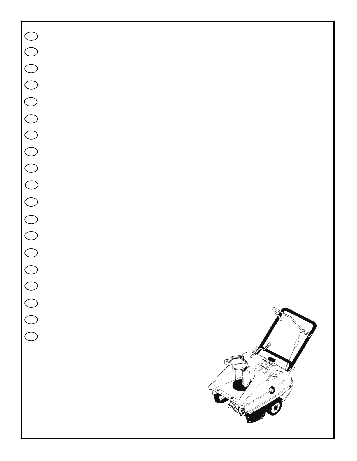
Know Your Snow Thrower (Figure 2)
Read this Instruction Book and safety rules be-
fore operation the snow thrower. Compare the
illustration with your snow thrower to familiarize
yourself with the location of various controls and
adjustments.
Controls & Equipment Features
(see Figure 2)
Crank Assembly (2) -- Changes the direction of
the discharge chute.
Chute Deflector (3) -- Changes the distance the
snow is thrown.
Discharge Chute (4) -- Changes the direction the
snow is thrown.
Auger Drive Lever (5) -- Starts and stops the au-
ger which propels the snow thrower.
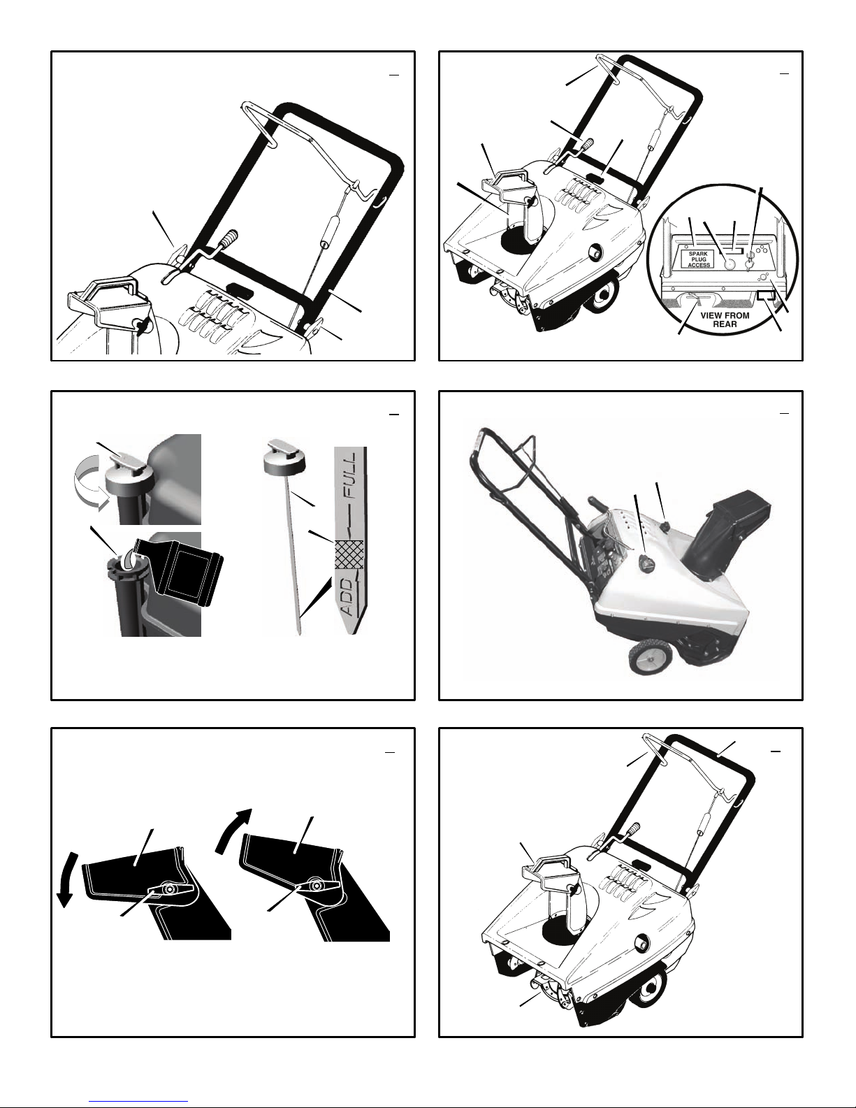
Engine Features
Stop Switch (8) -- If equipped, move to the ON
position to start the engine.
Ignition Key (8) -- If equipped, insert and turn to
the on position to start the engine.
Primer Button (9) -- Injects fuel directly into the
carburetor for fast starts in cold weather.
Electric Start Button (10) -- On electric start mod-
els, used to start the engine.
Switch Box (11) -- On electric start models, used
to attach a 220 volt electric power cord.
Recoil Starter Handle (12) -- Use to manually
start the engine.
Choke Control (14) -- Use to start a cold engine.
Spark Plug Access Panel (15) -- Remove to ac-
cess the spark plug.
How To Control
The Discharge Of The Snow
WARNING: Never direct the dis-
charge of snow toward bystanders.
WARNING: Always stop the engine
before unclogging the discharge
chute or the auger housing and be-
fore leaving the snow thrower.
1. (Figure 2) Turn the crank assembly (2) to
change the discharge direction of the snow.
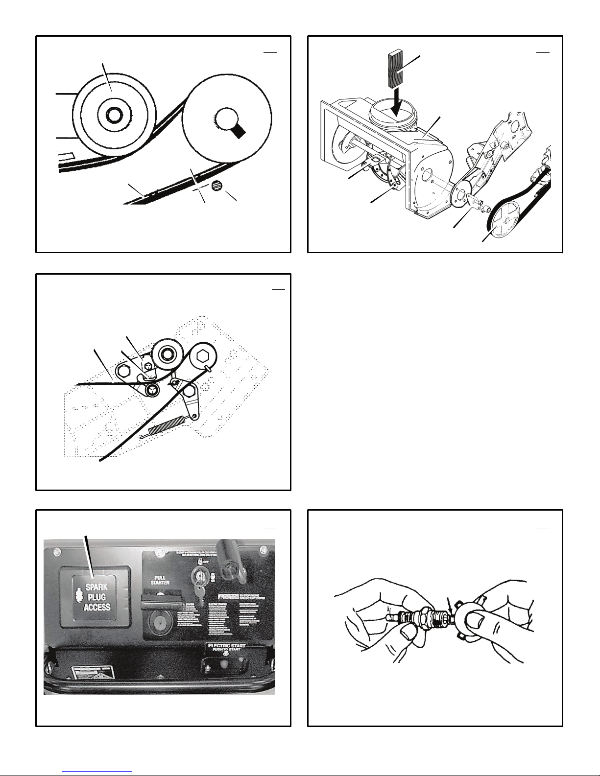
2. (Figure 5) Loosen the wing knob (1) on the
chute deflector (2).
3. Move the chute deflector (2) up for more
distance or down for less distance.
4. Tighten the wing knob (1).
How To Throw Snow (Figure 2)
1. Engage the auger drive lever (5).
2. To stop throwing snow, release the auger
drive lever (5).
WARNING: The operation of any
snow thrower can result in foreign
objects being thrown into the eyes,
which can result in severe eye damage.
Always wear safety glasses or eye shields
while operating the snow thrower. We rec-
ommend standard safety glasses or use a
wide vision safety mask over your glasses.
How To Stop Discharging Snow
(Figure 2)
1. To stop discharging snow, release the auger
drive lever (5).
2. To stop the engine, turn the ignition key (8)
to the off position.
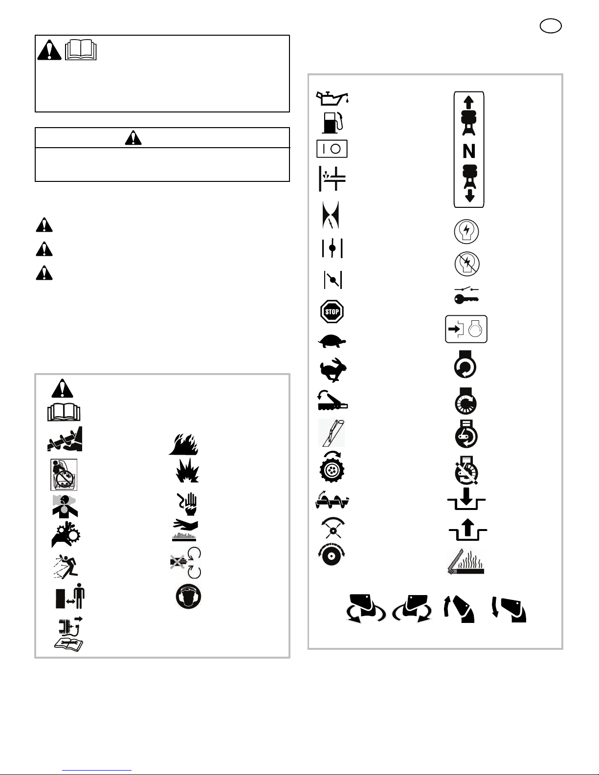
How To Move Forward (Figure 6)
1. Hold the auger drive lever (5) against the
handle (2). The auger will begin rotating.
2. To go forward, raise the handle (2) to allow
the rubber auger blades (1) to contact the
ground. Maintain a firm hold on the handle
(2) as the snow thrower starts to move for-
ward. Guide the snow thrower by moving the
handle (2) either left or right. Do not attempt
to push the snow thrower.
3. To stop, release the auger drive lever (5).
NOTE: If the auger continues to rotate, see
“How To Adjust The Auger Control Cable” in
the Service and Adjustments section.
Before Starting The Engine
1. Before you service or start the engine, famil-
iarize yourself with the snow thrower. Be
sure you understand the function and loca-
tion of all controls.
2. Make sure that all fasteners are tight.
3. Make sure the fuel tank is filled with fresh,
clean fuel.
4. Become familiar with the location of all con-
trols and understand their function.
5. Before starting the engine, make sure all
controls operate corrently.
How To Stop The Engine (Figure 2)
To stop the engine, turn the ignition key (8) to
the off position. Keep the ignition key (8) in a
safe place. The engine will not start without the
ignition key (8).
How To Start The Engine (Figure 2)
Models equipped with an Electric Starter
NOTE: An electric starter kit can be added to
recoil start engines. Electric starter kits are
available from your nearest authorized ser-
vice center.
WARNING: The starter is equipped
with a three--wire power cord and
plug and is designed to operate on
220 volt A.C. household current. The power
cord must be properly grounded at all times
to avoid the possibility of electrical shock
which can injure the operator. Carefully fol-
low all instructions in the “How To Start The
Engine” section. Make sure that your house
wiring is a three--wire grounded system. If
you are not sure, ask a licensed electrician.
If your house wire system is not a
three--wire grounded system, do not use
this electric starter under any conditions. If
your system is grounded but a three--hole
grounded receptacle is not available to start
the engine, have a three--hole grounded re-
ceptacle installed by a licensed electrician.
To connect a 220 volt A.C. power cord, al-
ways connect the power cord to the switch
box (11) on the engine first. Then, plug the
other end into the three--hole grounded re-
ceptacle. When disconnecting the power
cord, always unplug the end from the
three--hole grounded receptacle first.
How To Start A Cold Engine (Figure 2)
1. Fill the fuel tank with a fresh, clean fuel. See
“Fuel Recommendations” in the Assembly
section.
2. Move the choke control to FULL position.
3. Make sure the auger drive lever (5) is in the
disengaged (released) position.
4. Insert the ignition key (8) and turn to the on
position.
5. Move the choke control (14) to the full
choke position.
6. (Electric Start) Connect the power cord to
the switch box (11) located on the engine.
7. (Electric Start) Plug the other end of the
power cord into a three--hole, grounded 220
VOLT, A.C. receptacle. (See the WARNING
in this section).
8. Push the primer button (9). Every time you
push the primer button (9),waittwosec-
onds. For the number of times required to
push the primer button (9), see the engine
manufacturer’s instructions.
9. (Electric Start) Push on the electric start
button (10) until the engine starts. Do not
crank for more than 10 seconds at a time.
The electric starter is thermally protected. If
the electric starter overheates, it will auto-
matically stop and can only be restarted
when it has cooled to a safe temperature. A
wait of about 5 to 10 minutes is required to
allow the electric starter to cool.
10.(Recoil Start) Rapidly pull the recoil starter
handle (12). Do not allow the recoil starter
handle (12) to snap back. Slowly return the
recoil starter handle (12).
11. If the engine does not start in 5 or 6 tries,
See the “Trouble Shooting Chart” Instruc-
tions.
12.(Electric Start) When the engine starts, re-
lease the electric start button (10) and
move the choke control (14) to 1/2 choke
position. When the engine runs smoothly,
move the choke control (14) to the off posi-
tion.
13.(Electric Start) First disconnect the power
cord from the three--hole receptacle. Then,
disconnect the power cord from the switch
box (11).

GB
11
1740281
NOTE: In temperatures below 0°F, allow
the engine to warm up for several minutes
before blowing snow.
WARNING: Never run the engine
indoors or in enclosed, poorly ven-
tilated areas. Engine exhaust con-
tains carbon monoxide, an odorless and
deadly gas. Keep hands, feet, hair and
loose clothing away from any moving parts
located on the engine or the snow thrower.
The temperature of muffler and nearby
areas may exceed 150°F. Avoid these
areas.
How To Start A Warm Engine (Figure 2)
If an engine has been running and is still warm,
leave the choke control (14) in the off position
and do not push the primer button (9).Ifthe
engine fails to start, follow the instructions “How
To Start A Cold Engine”.
NOTE: Do not use the primer button (9) to
start a warm engine.
How To Start An Engine With A Frozen Electric
Starter (Figure 2)
If the electric starter is frozen and will not turn
the engine, follow the instructions below.
1. Pull out the recoil starter handle (12) as far
as possible.
2. Quickly release the recoil starter handle
(12). Allow the recoil starter handle (12) to
snap back against the recoil starter.
If the engine still fails to start, repeat the two pre-
vious steps until the engine starts. Then, contin-
ue with the directions “How To Start A Cold
Engine”.
To help prevent the possible freeze--up of the
recoil starter and of the engine controls, proceed
as follows after each snow removal job.
1. With the engine running, quickly pull the re-
coil starter handle (12) three or four times
with a continuous full arm stroke. This will
produce a loud clattering sound that is not
harmful to the engine or starter.
2. Stop the engine. Wipe all snow and moisture
from the carburetor cover, control levers and
cables. Also move the choke control (14)
and recoil starter handle (12) several times.
How To Clear A Clogged Discharge Chute
WARNING: Hand contact with the
rotating impeller inside the dis-
charge chute is the most common
cause of injury associated with snow blow-
ers. NEVER USE YOUR HAND TO CLEAN
OUT THE DISCHARGE CHUTE.
To Clear The Chute:
SSHUT OFF THE ENGINE!
SWait 10 seconds to be sure that the impel-
ler blades have stopped rotating.
SAlways use a clean-out tool, not your
hands.
How To Use A Clean-Out Tool
•Release the auger drive lever.
•Pull out or remove the safety/ignition key.
•Disconnect the spark plug wire.
•Do not place your hands in the auger or
discharge chute. Use a clean-out tool to
remove snow or debris.
Snow Throwing Tips
1. This snow thrower will propel itself forward
when the handle is raised enough to cause
the auger blades to contact the ground. The
auger should stop when auger control bar is
released. If it does not stop, see “How To Ad-
just The Auger Control Cable” in the adjust-
ment section.
2. Most efficient snow throwing is accomplished
when the snow is removed immediately after
if falls.
3. For complete snow removal, slightly overlap
each previous path.
4. Whenever possible, discharge the snow
down wind.
5. The distance the snow will be discharged
can be adjusted by moving the discharge
chute deflector. Raise the deflector for more
distance or lower the deflector for less dis-
tance.
6. In windy conditions, lower the chute deflector
to direct the discharged snow close to the
ground where it is less likely to blow into un-
wanted areas.
7. For safety and to prevent damage to the
snow thrower, keep the area to be cleared
free of stones, toys and other foreign objects.
8. Do not use the auger propelling feature when
clearing gravel or crushed rock driveways.
Move the handle down to slightly raise the
auger.
9. The forward speed of the snow thrower is
dependent on the depth and weight of the
snow. Experience will establish the most ef-
fective method of using the snow thrower un-
der different conditions.
10.After each snow throwing job, allow the en-
gine to run for a few minutes. The snow and
accumulated ice will melt off the engine.
11. Clean the snow thrower after each use.
12.Remove ice, snow and debris from the entire
snow thrower. Flush with water to remove all
salt or other chemicals. Wipe snow thrower
dry.
Dry And Average Snow
1. Snow up to eight inches deep can be re-
moved rapidly and easily by walking at a
moderate rate. For snow or drifts of a greater
depth,slow your pace to allow the discharge
chute to dispose of the snow as rapidly as
the auger receives the snow.
2. Plan to have the snow discharged in the di-
rection the wind is blowing.
Wet Packed Snow
Move slowly into wet, packed snow. If the wet,
packed snow causes the auger to slow down or
the discharge chute begins to clog, back off and
begin a series of short back and forth jabs into
the snow. These short back and forth jabs, four
to six inches, will “belch” the snow from the
chute.
Snow Banks And Drifts
In snow of greater depth than the unit, use the
same “jabbing” technique described above. Turn
the discharge chute away from the snow bank.
More time will be required to remove snow of
this type than level snow.

GB
12
1740281
MAINTENANCE CHART
CUSTOMER RESPONSIBILITIES
SERVICE RECORDS
Fill in dates as you
complete regular
service.
Before
Each
Use
First
2
Hours
Every
5
Hours
Every
10
Hours
Every
25
Hours Each
Season Before
Storage SERVICE DATES
Check And Tighten All Screws and Nuts √ √
Check Spark Plug √ √
Check Drive Belt √
Check Fuel √
Drain Fuel √
Lubricate Chute Control Flange √
MAINTENANCE
NOTE: Illustrations begin on page 3.
Use the following maintenance section to keep
your unit in good operating condition. All the
maintenance information for the engine is in the
engine manufacturer’s instructions. Before you
start the engine, read this book.
WARNING: Before you make an in-
spection, adjustment (except
carburettor), or repair, disconnect
thewirefromthesparkplug.
General Recommendations
The warranty on this snow thrower does not cov-
er items that have been subjected to operator
abuse or negligence. To receive full value from
the warranty, the operator must maintain the
snow thrower as instructed in this manual.
Some adjustments must be made periodically to
properly maintain the snow thrower.
Engine Power Rating Information
The gross power rating labels for individual gas
engine models meet or exceed SAE (Society of
Automotive Engineers) code J1940 (Small En-
gine Power & Torque Rating Procedure) and
rating performance has been obtained and cor-
rected in accordance with SAE J1995 (Revision
2002--05). Actual gross engine power may be
lower and is affected by, but not limited to, ambi-
ent operating conditions and engine to engine
variability. Given both the wide array of products
on which engines are placed, and the variety of
environmental issues applicable to operating the
equipment, the gas engine will not develop the
rated gross power when used in a given piece of
power equipment (actual “on--site” or net horse-
power). This difference is due to a variety of fac-
tors including, but not limited to, accessories (air
cleaner, exhaust, charging, cooling, carburetor,
fuel pump, etc.), application limitations, ambient
operating conditions (temperature, humidity, alti-
tude), and engine to engine variability.
After Each Use
•Check for any loose or damaged parts.
•Tighten any loose fasteners.
•Check and maintain the auger.
•Check controls to make sure they are
functioning properly.
•If any parts are worn or damaged, replace
immediately.
All adjustments in the Maintenance section of
this manual should be checked at least once
each season.
How To Remove The Top Cover
(Figure 7)
1. Remove the discharge chute (1).
2. Remove the fuel cap.
3. Remove the two bolts and nuts (2) from the
front of the top cover (3).
4. Remove the two bolts (4) from the left and right
side of the top cover (3).
5. Remove the eight screws (5) on the left and
right side of the top cover (3).
6. Remove the three screws (6) from the top por-
tion of the control panel.
7. Carefully pull the rear of the top cover (4) up
and over the gas tank.
8. To install the top cover (4), reverse the
above steps.
Lubrication
Before Storage (Figure 7)
1. Remove the top cover (3). See“HowToRe-
move The Top Cover”.
2. Lubricate the clute control flange (7). Apply
a clinging type of grease such as Lubriplate.
How To Adjust The Chute Crank
If the chute crank will not rotate fully to the left or
right, adjust as follows.
1. Remove the top cover. See “How To Remove
The Top Cover”.
2. (Figure 9) Loosen nuts (1).
3. Move the crank adjusting bracket (2) to
allow 1/8 inch (3mm) clearance (3) between
the notch in the flange (4) and the outer di-
ameter of the worm gear (5).
4. Tighten the nuts (1).
How To Adjust The Auger Control Cable
The auger control cable are adjusted at the fac-
tory. During normal use, the auger control cable
can become stretched and the auger drive lever
will not properly engage or disengage the auger.
1. (Figure 10) Remove the “Z” hook (1) from
the auger drive lever (2).
2. (Figure 11) Slide the cable boot (3) off the
cable adjustment bracket (4).
3. Push the bottom of the auger control cable
(5) through the cable adjustment bracket
(4) until the “Z” hook (6) can be removed.
4. Remove the “Z” hook (6) from the cable
adjustment bracket (4). Move the “Z” hook
(6) down to the next adjustment hole.
5. Pull the auger control cable (5) up through
the cable adjustment bracket (4).
6. Put the cable boot (3) over the cable ad-
justment bracket (4).
7. (Figure 10) Install the “Z” hook (1) to the
auger drive lever (2).
8. To check the adjustment, start the snow
thrower. Make sure the auger does not rotate
when the auger drive lever is released.
How To Remove The Belt Cover
(Figure 8)
1. If equipped, remove the heat shield (12)
from the rear of the belt cover (13).
2. Remove the four bolts and nuts (14) holding
the belt cover (13) to the auger housing.
3. Remove the one screw (15) holding the belt
cover (13) to the bottom cover (16).
4. To remove, hold the bottom portion of the
belt cover (13) and pull down and out.
5. To install the belt cover (13), reverse the
above steps.
How To Replace The Drive Belt
The drive belt is of special construction and
must be replaced with original factory replace-
ment belt available from your nearest authorized
service center.
1. Remove the belt cover. See “How To Re-
move The Belt Cover”.
2. (Figure 12) Remove the drive belt (1) from
the idler pulley (2).
3. Move the belt guide (4) away from the drive
belt (1).
4. To reduce pressure on the drive belt (1),
move the idler pulley (2) away from the
drive belt (1). Remove the drive belt (1)
from between the brake pad (3) and the roll-
er (5).

GB
13
1740281
5. Remove the old drive belt (1).
6. To install the new drive belt (1), reverse the
above steps.
7. Make sure the drive belt (1) is seated prop-
erly on the pulleys.
8. (Figure 13) Set the belt guide (4) to 3/32”
(2mm) clearance.
NOTE: When the auger control lever is
engaged, the belt guide (4) must be 3/32”
(2mm) from the drive belt (1).
9. Install belt cover. See “How To Remove The
Belt Cover”.
How To Replace The Auger (Figure 14)
1. Remove the belt cover. See “How To Re-
move The Belt Cover”.
2. Remove the drive belt. See “How To Replace
The Drive Belt”.
3. Remove the auger pulley (1) from the auger
shaft (threads are left hand; turn clockwise to
remove).
4. To keep the auger (6) from rotating, set a
2”x4” piece of wood (2) on the center
paddle (3) to secure auger (6).
5. Remove the fasteners from the bearing as-
sembly (4). Remove the bearing assembly
(4) from the auger housing (5).
6. Slide the auger (6) out of the bearing assem-
bly on the right side of the snow thrower.
7. Tip the auger (6) enough to allow the auger
(6) to slide out of the auger housing (5).
8. To install auger (6), reverse the above steps.
How To Adjust The Brake Pad
(Figure 15)
IMPORTANT: An adjustment is only neces-
sary if the brake pad has become loose or
has been removed. To adjust, proceed as
follows:
1. Remove the top cover. See “How To Remove
The Top Cover”.
2. Remove the belt cover. See “How To Re-
move The Belt Cover”.
3. Tie the auger drive lever to the handle. This
will engage the drive system.
4. Loosen the screw and nut that secure the
brake pad arm (1).
5. Set the clearance between the brake pad (2)
and the drive belt (3) to 1/8 inch (3mm).
6. Tighten the screw and nut that secure the
brake pad arm (1).
7. Connect the wire to the spark plug.
How To Replace The Spark Plug
NOTE: This spark ignition system meets all
requirements of the Canadian Interference--
Causing Equipment Regulations.
NOTE: This engine complies with all current
Australian and New Zealand limitations elec-
tromagnetic interference.
The spark plug is housed in the engine compart-
ment under the top cover and cannot be seen
under normal conditions.
1. (Figure 16) Open the spark plug access door
(1) on the control panel.
2. The spark plug and wire are now visible.
3. Remove the spark plug wire.
4. Clean the area around the spark plug base to
prevent dirt from entering the engine when the
spark plug is removed.
5. Remove the spark plug.
6. Check the spark plug. If the spark plug is
cracked, fouled or dirty, it must be replaced .
7. (Figure 17) Set the gap between the elec-
trodes of the new spark plug at .030 inch. Next,
install the spark plug in the cylinder head and
firmly tighten. Recommended torque is 18 to
20 foot pounds.
How To Prepare The Snow Thrower For
Storage
WARNING: Do not remove petrol
while inside a building, near a fire,
or while you smoke. petrol fumes
can cause an explosion or a fire.
1. Drain the fuel tank.
2. Let the engine run until it is out of petrol.
3. Remove the spark plug from the cylinder.
Pour one ounce of oil into the cylinder. Slow-
ly pull the recoil--start grip so that the oil will
protect the cylinder. Install a new spark plug
in the cylinder.
4. Thoroughly clean the snow thrower.
5. Lubricate all lubrication points. See the Main-
tenance section.
6. Be sure that all nuts, bolts and screws are
securely fastened. Inspect all visible moving
parts for damage, breakage and wear. Re-
place if necessary.
7. Cover the bare metal parts of the blower
housing and auger with spray rust preventa-
tive lubricant.
8. Put the unit in a building that has good ven-
tilation.
9. If the machine must be stored outdoors,
block up the snow thrower to be sure the en-
tire machine is off the ground.
10.Cover the snow thrower with a suitable pro-
tective cover that does not retain moisture.
Do not use plastic.
How To Order Replacement Parts
The replacement parts are shown either on the
back pages of this Instruction Book or in a
separate Parts List Book.
Use only manufacturer’s authorized or approved
replacement parts. The letter placed on the end
of the part number denotes the type of finish for
the part, C for chrome, Z for zinc, a PA for
purchased assembly. It is important that you
include this when ordering a part. Do not use
attachments or accessories not specifically
recommended for this unit. In order to obtain
proper replacement parts you must supply the
model number (see nameplate).
Replacement parts, except for the engine, trans-
mission, transaxle or differential, are available
from the store where the mower was purchased
or a service shop recommended by the store.
Warranty service is available only through Autho-
rized Service Dealers. Locate your nearest dealer
in our locator map at www.murray.com.
Replacement parts for the engine, transaxle, or
transmission, are available from the
manufacturer’s authorized service center found
in the yellow pages of the telephone directory.
Also, see the individual engine or transmission
warranties to order replacement parts.
When ordering the following information is
required:
(1) The Model Number
(2) Serial Number
(3) Part Number
(4) Quantity

GB
14
1740281
TROUBLE SHOOTING CHART
TROUBLE CAUSE CORRECTION
Difficult starting Defective spark plug. Replace spark plug.
Water or dirt in fuel system. Use carburetor bowl drain to flush and refill with
fresh fuel.
Engine runs erratic Blocked fuel line, empty gas tank, or stale petrol Clean fuel line; check fuel supply; add fresh
petrol
Engine stalls Unit running on CHOKE. Set choke lever to RUN position.
Engine runs erratic;
Loss of power Water or dirt in fuel system. Use carburetor bowl drain to flush and refill with
fresh fuel.
Excessive vibration Loose parts: damaged impeller Stop engine immediately and disconnect spark
plug wire. Tighten all bolts and make all
necessary repairs. If vibration continues, have
the unit serviced by a competent repairman.
Unit fails to propel itself Drive belt loose or damaged. Replace drive belt.
Unit fails to discharge snow Auger drive belt loose or damaged. Adjust auger drive belt; replace if damaged.
Auger control cable not adjusted correctly. Adjust auger control cable.
Discharge chute clogged. Stop engine immediately and disconnect spark
plug wire. Clean discharge chute and inside of
auger housing.
Foreign object lodged in auger Stop engine immediately and disconnect spark
plug wire. Remove object from auger.

GB
15
1740281
BRIGGS & STRATTON CORPORATION OWNER WARRANTY POLICY
Effective January 1, 2006 replaces all undated Warranties and all Warranties dated before January 1, 2006
Briggs & Stratton Corporation will repair or replace, free of charge, any part(s) of the product that is defective in material or workmanship or both.
Transportation charges on product submitted for repair or replacement under this warranty must be borne by purchaser. This warranty is effective
for the time periods and subject to the conditions stated below. For warranty service, find the nearest Authorized Service Dealer in your area. For
warranty service, find the nearest Authorized Service Dealer in our dealer locator map at www.murray.com.
THERE IS NO OTHER EXPRESS WARRANTY. IMPLIED WARRANTIES, INCLUDING THOSE OF MERCHANTABILITY AND FITNESS FOR A
PARTICULAR PURPOSE, ARE LIMITED TO ONE YEAR FROM PURCHASE, OR TO THE EXTENT PERMITTED BY LAW ANY AND ALL
IMPLIED WARRANTIES ARE EXCLUDED. LIABILITY FOR INCIDENTAL OR CONSEQUENTIAL DAMAGES ARE EXCLUDED TO THE
EXTENT EXCLUSION IS PERMITTED BY LAW. Some states or countries do not allow limitations on how long an implied warranty lasts, and
some states or countries do not allow the exclusion or limitation of incidental or consequential damages, so the above limitation and exclusion
may not apply to you. This warranty gives you specific legal rights and you may also have other rights which vary from state to state or country to
country.
LIMITED WARRANTY
WARRANTY TERMS
Consumer Commercial Condition of
Brand / Unit Use Use Warranty Term
Single Stage Snowthrower 1 year 90 days......... .............
Dual Stage Snowthrower 2 year 90 days.......... .............
The warranty period begins on the date of purchase by the first retail consumer or commercial end user, and continues for the period of
time stated in the table above. “Consumer use” means personal residential household use by a retail consumer. “Commercial use” means
all other uses, including use for commercial, income producing or rental purposes. Once product has experienced commercial use, it shall
thereafter be considered as commercial use for purposes of this warranty.
No warranty registration is necessary to obtain warranty on Murray branded products. Save your proof of purchase receipt. If you do not
provide proof of the initial purchase date at the time warranty service is requested, the manufacturing date of the product will be used to
determine the warranty.
ABOUT YOUR WARRANTY
We welcome warranty repair and apologize to you for being inconvenienced. Any Authorized Service Dealer may perform warranty
repairs. Most warranty repairs are handled routinely, but sometimes requests for warranty service may not be appropriate. For example,
warranty service would not apply to the product if damage occurred because of misuse, lack of routine maintenance, shipping, handling,
warehousing or improper installation. Similarly, the warranty is void if the serial number on the product has been removed or the product
has been altered or modified.
This warranty covers product related defective material and/or workmanship only. To avoid misunderstanding which might occur be-
tween the customer and the Dealer, listed below are some of the causes of product failure that the warranty does not cover.
•Normal Wear: Small Engine Powered Equipment, like all mechanical devices, needs periodic parts and service to perform well. Warranty does not
cover repair when normal use has exhausted the life of the product or part.
•Installation: This warranty does not apply to product that has been subjected to improper or unauthorized installation, alteration or modification. Nor
installations that prevent starting, cause unsatisfactory engine performance.
•Improper Maintenance: The life of this product depends upon the conditions under which it operates, and the care it receives. Recommended
maintenance and adjustment intervals are stated in the Operator’s Manual. Often product, such as tillers, edgers, rotary mowers, are used in dusty
or dirty conditions, which can cause what appears to be premature wear. Such wear, when caused by dirt, dust, or other abrasive material entering
the product because of improper maintenance is not covered by warranty. The warranty will not cover repairs due to problems caused by replace-
ment parts that are not original manufactured part(s).
•Incorrect and/or insufficient fuel or lubrication: This warranty does not cover damage caused by the use of stale fuel, or altered gasolines. Dam-
age to engine or engine components ie, combustion chamber, valves, valve seats, valve guides, burned starter motor windings caused by use of
alternate fuels such as liquified petroleum, natural gas, are not covered unless engine is certified for this operation. Parts which are scored or bro-
ken because product was operated with insufficient, contaminated or incorrect grade of lubricating oil as well as product components damaged due
to lack of lubrication are not covered.
•Operational Misuse: Proper operation of the product is stated in the Operator’s Manual. Product damaged by overspeeding, overheating, or opera-
tion in a confined area without sufficient ventilation. Product broken by excessive vibration caused by a loose engine mounting, loose or unbalanced
blades, impellers, overspeeding, or bent crankshaft due to striking of solid object. Damage or malfunctions resulting from accidents, abuse, or im-
proper servicing or freezing or chemical deterioration, as well as operating in excess of recommended capacities as outlined in the Operator’s
Manual are not covered.
•Routine tune-up, wear items or adjustments: This warranty excludes wear items such as oil, belts, blades, o-rings, filters, etc.
•Other exclusions: Repair or adjustments for part(s) that are not manufactured by Briggs & Stratton Corporation, are not covered, see warranty for
respective manufacturers. This warranty excludes failures due to acts of God and other force majeure events beyond the manufacturers con-
trol. Also excluded are used, reconditioned, and demonstration products.
Warranty service is available only through Authorized Service Dealers. Locate your nearest dealer in our locator map at www.murray.com.

216
1740281
EK atbilstības sertifikāts
EÜ vastavustunnistus
Ðéóôïðïéçôéêü Óõììüñöùóçò ÅÊ
DEG--Konformitätserklärung
GB EC Certificate of Conformity
FR Déclaration de conformité pour la CEE
ICertificato di conformita’ comunitario
ES Declaración de Conformidad
NL EG--Conformiteitsverklaring
SEU--konformitetsintyg
NEU--konformitetserklæring
DK EU--overensstemmelseserklæring
SF EY:n vaatimustenmukaisuustodistus
conforming to Directive 98/37/EC
conforming to Directive 89/336/EEC
conforming to Directive 2000/14/EC
conforming to Directive 2002/88/EC
entsprechend der Richtlinie 98/37/EG
entsprechend der Richtlinie 89/336/EWG
entsprechend der Richtlinie 2000/14/EG
entsprechend der Richtlinie 2002/88/EG
conforme à la directive 98/37/CE
conforme à la directive 89/336/CEE
conforme à la directive 2000/14/CE
conforme à la directive 2002/88/CE
conforme alla Direttiva 98/37/CE
conforme alla Direttiva 89/336/CEE
conforme alla Direttiva 2000/14/CE
conforme alla Direttiva 2002/88/CE
según la directiva 98/37/CE
según la directiva 89/336/CEE
según la directiva 2000/14/CE
según la directiva 2002/88/CE
overeen komstig de Richtlijn 98/37/EG
overeen komstig de Richtlijn 89/336/EEG
overeen komstig de Richtlijn 2000/14/EG
overeen komstig de Richtlijn 2002/88/EG
överensstämmande med direktiv 98/37/EG
överensstämmande med direktiv 89/336/EEG
överensstämmande med direktiv 2000/14/EG
överensstämmande med direktiv 2002/88/EG
overholder direktiv 98/37/EF
overholder direktiv 89/336/EØS
overholder direktiv 2000/14/EF
overholder direktiv 2002/88/EF
overholder direktiv 98/37/EF
overholder direktiv 89/336/EØF
overholder direktiv 2000/14/EF
overholder direktiv 2002/88/EF
naudattaa direktiiviä 98/37/EY
naudattaa direktiiviä 89/336/ETY
naudattaa direktiiviä 2000/14/EY
naudattaa direktiiviä 2002/88/EY
Certyfikat zgodnoœci EC
zgodnoœæ z dyrektyw¹ 98/37/EC
zgodnoœæ z dyrektyw¹ 89/336/EEC
zgodnoœæ z dyrektyw¹ 2000/14/EC
zgodnoœæ z dyrektyw¹ 2002/88/EC
PL
LT atitinka direktyvą98/37/EC
atitinka direktyvą89/336/EEC
atitinka direktyvą2000/14/EC
atitinka direktyvą2002/88/EC
EC atitikties sertifikatas
Ha 98/37/EC Direktívának megfelelõen
a 89/336/EEC Direktívának megfelelõen
a 2000/14/EC Direktívának megfelelõen
a 2002/88/EC Direktívának megfelelõen
EC Megfelelõségi Nyilatkozat
EE Kooskõlas direktiiviga 98/37/EÜ
Kooskõlas direktiiviga 89/336/EMÜ
Kooskõlas direktiiviga 2000/14/EÜ
Kooskõlas direktiiviga 2002/88/EÜ
GR óýìöùíá ìå ôçí Ïäçãßá 98/37/ÅÊ
óýìöùíá ìå ôçí Ïäçãßá 89/336/ÅÏÊ
óýìöùíá ìå ôçí Ïäçãßá 2000/14/ÅÊ
óýìöùíá ìå ôçí Ïäçãßá 2002/88/ÅÊ
LV atbilstība direktīvai 98/37/EK
atbilstība direktīvai 89/336/EEK
atbilstība direktīvai 2000/14/EK
atbilstība direktīvai 2002/88/EK
CZ v souladu se smìrnicí 98/37/ES
v souladu se smìrnicí 89/336/EHS
v souladu se smìrnicí 2000/14/ES
v souladu se smìrnicí 2002/88/ES
ES prohlášení o shodì
SK v skladu z direktivo 98/37/ES
v skladu z direktivo 89/336/EGS
v skladu z direktivo 2000/14/ES
v skladu z direktivo 2002/88/ES
ES izjava o skladnosti
RU
ñîîòâåòñòâó˚ùèé Äè˜åêòèâå 98/37/EC
ñîîòâåòñòâó˚ùèé Äè˜åêòèâå 89/336/EEC
ñîîòâåòñòâó˚ùèé Äè˜åêòèâå 2000/14/EC
ñîîòâåòñòâó˚ùèé Äè˜åêòèâå 2002/88/EC
Ñåðòèôèêàò ñîîòâåòñòâèÿ ñòàíäàðòàì
è íîðìàì ÅÑ (Åâðîïåéñêîãî Ñîþçà)

217
1740281
erklären in alleiniger Verantwortung, daß das Produkt
declare in sole responsibility, that the product
déclarons sous notre seule responsabilité que le produit
dichiariamo sotto la nostra piena responsabilità che il prodotto
declaramos bajo responsabilidad propia que el producto
verklaren enig in verantwoording, dat het produkt
intygar med ensamansvar att nedanstående produkt
erklærer som eneansvarlig at produktet
erklærer som eneansvarlig, at produktet
ilmoitamme yksin vastaavamme, että tuote
Kinnitame omal vastutusel, et antud toode
Ý÷ïíôáò ðëÞñç åõèýíç, üôé ôï ðñïúüí
Saját kizárólagos felelõsségünkre kijelentjük, hogy a termék
paziņojam ar pilnu atbildību, ka šis produkts
Pareiškiame kad gaminys
niniejszy oœwiadczamy, ¿e produkt
prohlašuje na svou výluènou odpovìdnost, že produkt
v izkljuèni odgovornosti izjavlja, da je proizvod
çàâëåì ïîä èíäèâèäóàëüíó˚ îòâåòñòâåííîñòü, …òî èçäåëèå
Wir/We/Nous/Noi/Nosotros/Wij/Vi/Vi/Vi/Me/Meie /
Äçëþíïõìå /Mi /Mēs/Mes /My /Výrobce/Mi/‹àñòîùèì ìû
621504x117NA
(Fabrikat, Typ) (Make, model) (Marque, modèle) (Marca, tipo) (Marca,
modelo) (Fabricant, type) (Fabrikat, typ) (Fabrikat, type) (Mærke, type)
(Merkki, malli) (Mark, mudel) (ÌÜñêá, ìïíôÝëï) (Gyártmány, modell)
(Izstrādājums, modelis) (Markė, modelis) (marka, model) (Druh, model)
(fabrikat, tip) (Ìàðêà, ìîäåëü)
Briggs & Stratton Corporation
Yard Power Products Group
Port Washington, WI 53074
auf das sich diese Erklärung bezieht, den einschlägigen Anforderungen der Richtlinie 98/37/EG, der Richtlinie 2000/14/EG
(Konformitätsbewertungsverfahren gemäß Anhang VI), Richtlinie 2002/88/EG und der Richtlinie 89/336/EWG und aktuellen
Ergänzungen entspricht
to which this certificate applies, conforms to the requirements of Directive 98/37/EC,Directive 2000/14/EC (conformity assessment
procedure according to Annex VI), 2002/88/EC and Directive 89/336/EEC and current amendments
faisant l’objet de la déclaration est conforme aux prescriptions stipulées dans la Directive 98/37/CE, la directive 2000/14/CE (procédure
d’évaluation de conformité selon l’annexe VI), la directive 2002/88/CE et la directive 89/336/CEE et ses modifications courantes
cui la presente dichiarazione si riferisce, è conforme ai requisiti de Direttiva 98/37/CE, della Direttiva 2000/14/CE (procedura di
valutazione della conformità secondo l’Allegato VI), della Direttiva 2002/88/CE e della Direttiva 89/336/CEE e correnti emendamenti
al cual se refiere la presente declaración corresponde a las exigencias de la directiva 98/37/CE, de la directiva 2000/14/CE (los
procedimientos de evaluación de conformidad según el Anexo VI), de la directiva 2002/88/CE y de la directiva 89/336/CEE y
enmiendas vigentes
waarop deze verklaring betrekking heeft, overeenkomt met de eisen van de richtlijn 98/37/EG, de richtlijn 2000/14/EG
(conformiteitsbeoordelingsprocedure volgens bijlage VI), de richtlijn 2002/88/EG en de richtlijn 89/336/EEG en huidige wijzigingen
för vilket detta intyg gäller, uppfyller kraven enligt direktiv 98/37/EG, direktiv 2000/14/EG (procedur för bedömning av överensstämmelse
enligt tillägg VI),direktiv 2002/88/EG och direktiv 89/336/EEG samt allmäna tillägg
som denne erklæring vedrører, oppfyller krav i direktiv 98/37/EF, direktiv 2000/14/EF (konformitetsvurderingsprosedyre i henhold til
anneks VI), direktiv 2002/88/EF og direktiv 89/336/EØS og aktuelle vedlegg
som denne erklæring vedrører, overholder krav i direktiv 98/37/EF, direktiv 2000/14/EF (konformitetsvurderingsprocedure iflg. Annex
VI),direktiv 2002/88/EF og direktiv 89/336/EØF og ændringer
johon tämä ilmoitus liittyy, vastaa direktiivissä 98/37/EY, direktiivissä 2000/14/EY (Liitteen VI mukaisten yhdenmukaisuuden
arviointitoimien), direktiivissä 2002/88/EY, direktiivissä 89/336/ETY ja nykyisissä muutoksissa mainittuja vaatimuksia
mille kohta tunnistus kehtib, on kooskõlas direktiiviga 98/37/EÜ,direktiiviga 2000/14/EÜ (vastavushindamismenetlus vastavalt lisale VI),
2002/88/EÜ ja direktiiviga 89/336/EMÜ koos jooksvate muudatustega
óôï ïðïßï áöïñÜ ôï ðáñüí ðéóôïðïéçôéêü, ðëçñïß ôéò áðáéôÞóåéò ôçò Ïäçãßáò 98/37/ÅÊ,ôçò Ïäçãßáò 2000/14/ÅÊ (äéáäéêáóßá
áîéïëüãçóçò ôçò óõììüñöùóçò óýìöùíá ìå ôï ÐáñÜñôçìá VI), 2002/88/ÅÊ êáé ôçò Ïäçãßáò 89/336/ÅÏÊ êáé ôéò
ôñïðïðïéÞóåéò ôïõò
amelyre ezen nyilatkozat vonatkozik, megfelel a 98/37/EC Direktíva, 2000/14/EC Direktíva (a VI Függeléknek megfelelõ megfelelõség
felbecsülési eljárás), 2002/88/EC valamint 89/336/EEC Direktívák és legújabb módosításaik elõírásainak.
Uz kuru attiecas šis sertifikāts, atbilst Direktīvas 98/37/EK,un Direktīvas 2000/14/EK prasībām (atbilstības novērtēšanas procedūra
saskaņā ar Pielikumu VI), 2002/88/EK un Direktīvu 89/336/EEK un kārtējiem grozījumiem
Kuriam priklauso šis sertifikatas, atitinka direktyvos 98/37/EC,direktyvos 2000/14/EC (atitikties atestavimo procedūra pagal Annex
(priedą) Nr.VI), 2002/88/EC ir direktyvos 89/336/EEC reikalavimus ir jųesamus pataisymus
którego dotyczy ten certyfikat, jest zgodny z wymaganiami dyrektywy 98/37/EC,dyrektywy 2000/14/EC (procedura oceny zgodnoœci
zgodnie z za³¹cznikiem VI), 2002/88/EC i dyrektyw¹ 89/336/EEC oraz bie¿¹cymi poprawkami.
k nìmuž se vydává toto potvrzení, splòuje požadavky smìrnice 98/37/ES,smìrnice 2000/14/ES (postup posouzení shody dle pøílohy
VI), 2002/88/ES a smìrnice 89/336/EHS v platném znìní
na katerega se nanaٛa ta izjava, v skladu z zahtevami direktive 98/37/ES, direktive 2000/14/E, direktive 2002/88/ES in direktive 89/336/EGS ter
aktualnimi dopolnili.
ê êîòî˜îìó ï˜èìåíèì äàííûé ñå˜òèôèêàò, ñîîòâåòñòâóåò ò˜åáîâàíèì Äè˜åêòèâû 98/37/EC,Äè˜åêòèâû 2000/14/EC
(ï˜îöåäó˜à îöåíêè ñîîòâåòñòâèñîãëàñíî fi˜èëî¥åíè˚ VI), 2002/88/EC è Äè˜åêòèâû 89/336/EEC è äåéñòâó˚ùèì ïîï˜àâêàì

218
1740281
Zursachgerechten Umsetzung der EG--Richtlinien wurde(n) folgende Norm(en) und/oder technische Spezifikation(en) herangezogen:
ISO 8437, BS EN 1033:1996, EN ISO 3744:1994
To effect correct application of the EEC Directives, the following standards and/or technical specifications were consulted: ISO 8437,
BS EN 1033:1996 and/or ISO 3744:1994
Pour mettre en pratique les Directives de la CEE, il a été tenu compte de la/des norme(s) et/ou de la/des spécification(s) technique(s)
suivante(s): ISO 8437, BS EN 1033:1996, EN ISO 3744:1994
Per un’appropriato riscontro della normativa CEE, è (sono) stata(e) consultata(e) la(e) seguente(i) norma(e) e/o specifica(che)
tecnica(che): ISO 8437, BS EN 1033:1996, EN ISO 3744:1994
Con el fin de realizar de forma adecuada las exigencias en las normativas de la CEE (fué(ron) consultada(s) la(s) siguiente(s)
normativa(s) y especificación(es) técnica(s): ISO 8437, BS EN 1033:1996, EN ISO 3744:1994
Om de EG--richtlijnen in juiste vorm om te zetten, is/zijn van volgende norm(en) en/of technische specificatie(s) gebruik gemaakt: ISO
8437, BS EN 1033:1996, EN ISO 3744:1994
Följande norm(er) och/eller teknisk(a) specifikation(er) har legat till grund för ett fackmässigt införande av de i EU--normerna: ISO 8437,
BS EN 1033:1996, EN ISO 3744:1994
Følgende normer og/eller tekniske spesifikasjoner er lagt til grunn for gjennomførelse av EU--retningslinjenes: ISO 8437, BS EN
1033:1996, EN ISO 3744:1994
Til gennemførelse af de EF--direktivet er følgende standard(er) og/eller tekniske specifikation(er) anvendt: ISO 8437, BS EN 1033:1996,
EN ISO 3744:1994
ETY--direktiivien oikean soveltamisen varmistamiseksi on käytetty seuraavia standardeja ja/tai teknisiä erittelyjä: ISO 8437, BS EN
1033:1996, EN ISO 3744:1994
EMÜ direktiivide õiguspäraseks kohaldamiseks arvestati allpool nimetatud standardite ja/või tehniliste spetsifikatsioonidega: ISO 8437,
BS EN 1033:1996 ja/või ISO 3744:1994
Ãéá ëüãïõò ïñèÞò åöáñìïãÞò ôùí Ïäçãéþí ÅÏÊ, åëÞöèçóáí õðüøç ôá ðáñáêÜôù ðñüôõðá êáé/Þ ôå÷íéêÝò ðñïäéáãñáöÝò: ISO
8437, BS EN 1033:1996 êáé/Þ ISO 3744:1994
Az EEC Direktívák megfelelõ alkalmazása céljából a következõ szabványokat és/vagy mûszaki elõírásokat vizsgálták meg: ISO 8437,
BS EN 1033:1996 és/vagy a ISO 3744:1994
Lai panāktu pareizu EEK Direktīvu piemērošanu, ievēroti sekojoši standarti un/vai tehniskie noteikumi: ISO 8437, BS EN 1033:1996
un/vai ISO 3744:1994
Tam kad pritaikyti atitinkamas Europos Sąjungos direktyvas, buvo atsižvelgta įsekančius standartus ir/arba techninius reikalavimus:
ISO 8437, BS EN 1033:1996 ir/arba ISO 3744:1994
Aby zapewniæ w³aœciwe zastosowanie dyrektyw EEC, sprawdzono nastêpuj¹ce standardy i/lub specyfikacje techniczne: ISO 8437, BS
EN 1033:1996 i/lub ISO 3744:1994
Pro správnou aplikaci smìrnic EHS bylo postupováno podle následujících norem a/nebo technických specifikací: ISO 8437, BS EN
1033:1996 a/nebo ISO 3744:1994
Za strokovno uresnièevanje direktiv ES smo sledili naslednjim standardom in/ali tehniènim specifikacijam: ISO 8437, BS EN 1033:1996,
EN ISO 3744;1994
Äëîñóùåñòâëåíèï˜àâèëüíîãî ï˜èìåíåíèÄè˜åêòèâ EEC, áûëè èñïîëüçîâàíû ñëåäó˚ùèå ñòàíäà˜òû è/èëè òåõíè…åñêèå
óñëîâè: ISO 8437, BS EN 1033:1996 è/èëè ISO 3744:1994
Bauart
Category
Categorie
Categoria
Categoría
Categorie
Kategori
Kategori
Kategori
Kategoria
Kategooria
Êáôçãïñßá
Kategória
Kategorija
Kategorija
Kategoria
Kategorie
Kategorija
ÿàòåãî˜è
SCHNEEFRÄSE
SNOW THROWER
CHASSE--NEIGE
SPAZZANEVE
QUITANIEVES
SNEEUWRUIMER
SNÖSLUNGA
SNØFRESER
SNEBLÆSER
LUMILINKO
LUMEKAHUR
ÖuóçôÞñáò ×ÉïíÉïý
HÓMARÓ
SNIEGA METٛJS
SNIEGO VALYMO MAךINA
ODŒNIEŽARKA
SNٛHOVÁ FRÉZA
SNEŽNA FREZA
Ñ‹Åø››˝¤Ñ‚¤‚Å⁄Ü
Fabrikmarke / Make / Marque / Marca / Marca / Merk / Fabriksmärke /
Merke / Mærke / Merkki / Mark /ÌÜñêá /Gyártmány /Izstrādājums /Markė/Model /Druh /
Fabrikat / flà˜êà
PARTNER
Typ / Type / Type / Tipo / Tipo / Model / Typ / Type / Type /
Tyyppi / Tüüp /Ôýðïò /Típus /Tips / Tipas / Typ /Typ /Tip /‚èï 5HP/21

219
1740281
Erklärter Schalleistungspegel
Declared sound power level
Niveau de puissance acoustique déclaré
Livello di potenza acustica dichiarato
Nivel declarado de potencia acústica
Erkend geluidsvermogensniveau
Angiven ljudnivå
Deklarert lydnivå
Deklareret lydniveau
Ilmoitettu äänen tehotaso
Deklareeritud helitase
Äçëùèåßóá óôÜèìç èïñýâïõ
Névleges hangerõszint
Deklarētais skaņas jaudas līmenis
Deklaruojamas triukšmo lygis
Deklarowany poziom g³oœnoœci dŸwiêku
Deklarovaná hladina akustického výkonu
Deklarirana raven zvoène moèi
Çàâëåííûé ó˜îâåíü çâóêîâîé ìîùíîñòè
104 dB (A)
Gemessener Schalleistungspegel
Measured sound power level
Niveau de puissance acoustique mesuré
Livello di potenza acustica misurato
Nivel medido de potencia acústica
Gemeten niveau van geluidssterkte
Uppmätt ljudstyrksnivå
Målt lydnivå
Målt lydniveau
Mitattu äänentehotaso
Mõõdetud helitase
Ìåôñçèåßóá óôÜèìç èïñýâïõ
Mért hangerõszint
Izmērītais skaņas jaudas līmenis
Pamatuotas triukšmo lygis
Zmierzony poziom g³oœnoœci dŸwiêku
Zmìøená hladina akustického výkonu
Izmerjena raven zvoène moèi
¤çìå˜åííûé ó˜îâåíü çâóêîâîé ìîùíîñòè
100 dB (A)
Art des Räumwerks
Type of cutting device
Genre du dispositif de déneigement
Tipo di dispositivo di rimozione della neve
Tipo de dispositivo de remoción de nieve
Type sneeuwverwijderingsapparaat
Typ av snöavlägsningsanordning
Type freserredskap
Type snefjernelsesanordning
Lumenpoistovälineen tyyppi
Lõikeseadme tüüp
ÔýðïòäéÜôáîçòêïðÞò
Vágószerkezet típusa
Griezējierīces tips
Pjovimo prietaiso tipas
Typ urz¹dzenia tn¹cego
Typ øezného mechanismu
Naèin odstranjevanja snega
‚èï ˜å¥óùåãî óñò˜îéñòâà
ROTIERENDE SCHNEESCHRAUBE
ROTATING AUGER
FRAISE ROTATIVE
TRIVELLA RUOTANTE
CUCHILLA GIRATORIA
ROTEREND BOORBLAD
ROTERANDE SKRUV
ROTERENDE SKRUE
ROTERENDE SKRUE
PYÖRIVÄ SYÖTTÖKIERUKKA
PINNASEPUUR
Ðåñéóôñïöéêü ôñõôôÜíé
FORGÓ CSIGA
ROTĒJOŠAIS URBIS
BESISUKANTIS SRAIGTAS
OBROTOWA ŒRUBA ODŒNIEŽAJ¥CA
ROTUJÍCÍŠNEK
ROTAÈNÁ ZÁVITOVKA
◊ˆæÂæ˙¤ÉÑß Æ‹Åÿ
Schnittbreite / Width of cut / Largeur de coupe / Ampiezza di taglio /
Ancho de corte / Snijbreedte / Skärbredd /
Snittbredde / Skærebrede / Leikkuujäljen leveys / Lõike laius /Åýñïò êïðÞò /
Vágásszélesség /Griešanas platums /Pjovimo plotis /Szerokoœæ ciêcia /Šíøka øezu /
Širina reza /Æè˜èíà çàõâàòà
53 cm

220
1740281
Y
Y
Y
Y
MM DD
Port Washington, WI USA 2006.06.02 President
(Ort und Datum der Ausstellung) (Name, Funktion und Unterschrift des Befugten)
(Place and date of issue) (Name and job function of authorized person)
(Lieu et date) (Nom, fonction et signature de la personne autorisée)
(Luogo e data del rilascio) (Nome, qualifica e firma dell’incaricato)
(Lugar y fecha de expedición) (Nombre, función y firma del encargado)
(Plaats en datum van de verklaring) (Naam, functie en handtekening van bevoegd persoon)
(Utfärdat ort/datum) (Namn, befattning och underskrift av behörig medarbetare)
(Sted og datum) (Bemyndigtes navn, funksjon og underskrift)
(Sted og dato) (Bemyndigedes navn, funktion og underskrift)
(Ilmoitus annettu paikka ja päiväys) (Valtuutetun henkilön nimi ja tehtävä)
(Väljaandmise koht ja kuupäev) (Volitatud isiku nimi ja ametikoht)
(Ôüðïò êáé çìåñïìçíßá Ýêäïóçò) (Ïíïìáôåðþíõìï êáé éäéüôçôá ôïõ åîïõóéïäïôïýìåíïõ áôüìïõ)
(Kiadás helye és dátuma) (A meghatalmazott személy neve és munkahelyi beosztása)
(Izlaides vieta un datums) (Pilnvarotās personas vārds un darba funkcijas)
(Vieta ir data) (Įgalioto atstovo vardas ir pareigos)
(Data i miejsce wystawienia) (Nazwa i stanowisko uprawnionej osoby)
(Místo a datum vydání) (Jméno a funkce autorizované osoby)
(Kraj in datum izdaje) (Ime, funkcija in podpis upravièene osebe)
(flåñòî è äàòà îôî˜ìëåíè)(·àìèëèè äîë¥íîñòü óïîëíîìî…åííîãî ëèöà)
Table of contents
Other Partner Snow Blower manuals