INSTALLATION INSTRUCTIONS
3501 Kennedy Rd, PO Box 5222, Janesville, WI 53547-5222
P/N DS-319934
REVISED 3/2012 Page 2 of 4
PARTS UNLIMITED
REAR SPEAKER KIT FOR 1988-2000 GL1500
P/N DS-319934
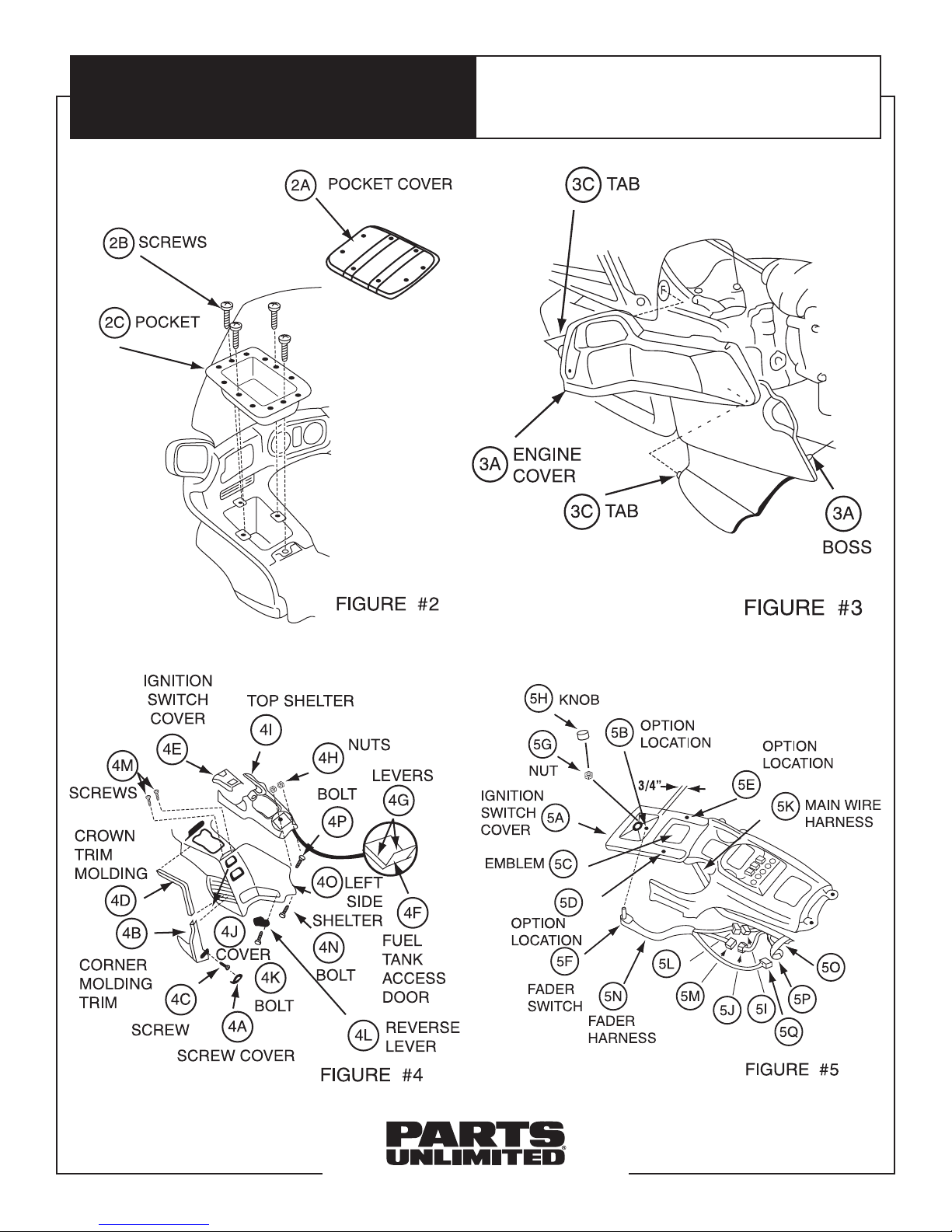
10. Open fuel tank access door (Item #4F) and release
levers (Item #4G) located on either side. Using a 10mm
wrench, remove two acorn nuts (Item #4H) at rear of
top shelter. With handlebars straight ahead, remove
top shelter (Item #4I) by grasping under rear and pulling
sharply upward and to rear.
11. Pull reverse lever cover (Item #4J) outward and rear.
Pivot to expose socket bolt (Item #4K). Using 6mm hex
wrench, remove socket bolt (Item #4K) and remove
reverse lever (Item #4L) from motorcycle. Using #2
Phillips screwdriver, remove two screws (Item #4M)
at top front of left side shelter. Using 10mm wrench,
remove special bolt (Item #4N) at bottom rear of left
side shelter. Remove left-side shelter (Item #4O) by
lifting up and over bolt (Item #4P) at top rear corner.
12. Using center punch and hammer, mark fader switch
mounting hole location on ignition switch cover (Item
#5A). You may choose one of three locations: Centered
in switch recess area (Item #5B) about 3/4” from back
edge of recess; centered and in line with GL15000
emblem (Item #5C) on left side; or centered and in line
with GL1500 emblem (Item #5C) on right side.
NOTE: Check underneath for interference or obstructions
prior to locating hole.
13. Using electric drill and 9/32” bit, drill mounting hole
through ignition switch cover (Item #5A). Mount fader
switch (Item #5F) with nut (Item #5G) on top and
tighten securely with 10mm wrench. Push fader switch
chromed knob (Item #5H) in place onto switch.
14. Disconnect white four-pin connectors (Item #5I, 5J) on
motorcycle and attach to male and female white four-
pin connectors (Item #5L, 5M) on fader wiring harness
(Item #5N). Remove tape (Item #5O) holding unused
black four-pin connector (Item #5P) to main harness
and connect to black four-pin connector (Item #5Q) on
fader harness.
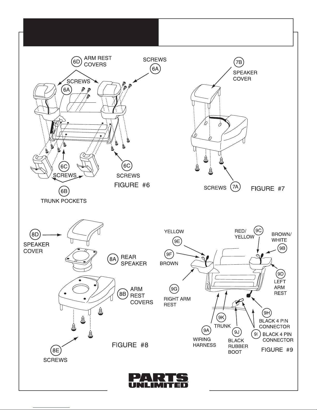
15. Using #2 medium Phillips screwdriver, remove six
mounting screws (Item #6A) located inside trunk, left
and right trunk pockets (Item #6B), eight mounting
screws (Item #6C) and both left and right armrest
cover assemblies (item #6D). With #2 medium Phillips
screwdriver, also remove eight mounting screws (Item
#7A) and both armrest speaker covers (Item #7B).
16. Place left and right rear speakers (Item #8A) into armrest
covers cavity from top (Item #8B). Reattach speaker
covers (Item #8D) using screws (Item #7A).
17. Install rear speaker wiring harness (Item #9A) as follows:
Terminal end with gray (Item #9B) and blue (Item #9C)
wires goes into left armrest (Item #9D). Terminal end
with brown (Item #9F) and yellow (Item #9F) wires goes
into right armrest (Item #9G). Black four-pin connector
(Item #9H) plugs into black four-pin connector (Item #9I)
located in black rubber boot (Item #9J) on main wir-
ing harness in under-seat area near large white 24-pin
connector. Wiring harness (Item #9A) is run under front
lower edge of trunk (Item #9K).
18. Connect rear speakers to wiring harness, making
certain sufficient slack is available to open and close
trunk without undue pressure on connectors. Reinstall
armrest cover assemblies (being careful not to pinch
wiring harness) and trunk pocket cover by reversing
Step #15.
19. Operate radio and fader to make certain system works
properly. Reinstall all other removed items by reversing
Steps #1-11.