Parvus DURAVIS 3400 User manual

User Manual
MNL-0545-01 revB
REF ECO-1119
Effective: 27-APR-07
DURAVIS 3400

MNL-0545B-01
Disclaimer
Although the information contained herein has been carefully verified, Parvus Corporation assumes no
responsibility for errors that might appear in this document, or for damage to property or persons resulting from
improper use of this manual or related software. Parvus reserves the right to change the contents and form of
this document, as well as the features and specifications of its products at any time without notice. The
information in this publication does not represent a commitment on the part of Parvus. This document contains
proprietary information that is protected by copyright. All rights are reserved. No part of this document may be
photocopied, reproduced, or translated into another language without the prior written consent of Parvus.
Parvus Corporation
3222 S. Washington St.
Salt Lake City, Utah, USA 84115
Phone: +1 (801) 483-1533
Toll-Free: +1 (800) 483-3152
Main: +1 (801) 483-1533
Fax: +1 (801) 483-1523
Email: Sales: sales@parvus.com
Support: [email protected]m
Web-site: http://www.parvus.com
Parvus is the U.S. arm of the Eurotech Group (www.eurotech.com), a global family of technology companies
focused on innovative embedded and high performance computing solutions.
Trademarks
Trademarks and registered trademarks appearing in this document are the property of their respective owners.

DuraVIS-3400 3
IMPORTANT INFORMATION TO THE USER
Before proceeding further, please carefully read the following paragraphs:
Safety Notices and warnings
FCC information and compliance
This device has been designed to comply within the limits of a Class B digital device pursuant to Part 15 of the
FCC Rules. These limits are designed to provide reasonable protection against harmful interference. The device
generates, uses, and can radiate radio frequency energy and, if not installed and used in accordance with the
instructions, may cause harmful interference to radio communications or to devices that are not appropriately
shielded.
Parvus is not responsible for any radio or device, which may be affected by harmful interference. Appropriate
shielding of susceptible devices is not the responsibility of Parvus. Further, Parvus is not responsible for
unauthorized modifications of Parvus equipment including the substitution or attachment of cables and/or other
unauthorized equipment. If electrical interference is harmfully affecting a device, it is the responsibility of the user
to correct this interference.
In order to minimize the affects of electrical interference, use only shielded data cables with the system.
In accordance with FCC 15.21, changes or modifications not expressly approved by the party responsible for
compliance could void the user’s authority to operate the equipment.
Emissions information for Canada
This Class B digital apparatus complies with Canadian ICES-003. Cet appareil numérique de la classe B est
conforme à la norme NMB-003 du Canada.
CE Marking
This equipment complies with the requirements for CE marking when used in a residential,
commercial, vehicular or light industrial environment.

MNL-0545B-01
RAEE
The information below is issued in compliance with the regulations as set out by the 2002/96/CE directive,
subsequently superseded by 2003/108/CE, and refers electrical and electronic equipment and the management
of their waste (WEEE). When disposing of a device, including all of its components, subassemblies and
materials that are an integral part of the product, you should take the WEEE directive into consideration.
This symbol has been attached to the equipment or, in the case that this is not possible, on the
packaging, instruction literature and/or the guarantee sheet. By using this symbol it states that the
device has been marketed after August 13th 2005, and implies that you must separate all of its
components when possible, and dispose of them in accordance with local waste disposal legislations.
¾Because of the substances present in the equipment, an improper use or disposal of the refuse can cause
damage to human health and to the environment.
¾With reference to RAEE, it is compulsory to not dispose of the equipment with normal urban refuse,
arrangements should be instigated for separate collection and disposal.
¾For more detailed information about recycling of RAEE, please contact your local waste
collection body.
¾In case of illicit disposal, sanctions will be levied on transgressors.
RoHS
This device, including all it components, subassemblies and the consumable materials that are an integral
part of the product, has been manufactured in compliance with the European directive 2002/95/EC known as
the RoHS directive (Restrictions on the use of certain Hazardous Substances), this directive targets the
reduction of certain hazardous substances previously used in electrical and electronic equipment (EEE).
Anti-static precautions
Always use appropriate antistatic precautions when handing any board. This is to avoid damage
caused by ESD (Electro Static Discharge).

DuraVIS-3400 5
Conventions
The following table lists the conventions that are used throughout this manual.
Icon Notice Type Description
Information note Important features or instructions
Warning Information to alert you to potential
damage to a program, system or device
or potential personal injury
The “Mode” of the register:
R/W Read and write register.
RO Read only register.
W Meaning of the register when written.
R Meaning of the register when read.
Hexadecimal numbers:
Hexadecimal numbers are indicated with an “h” suffix (for example: 11Ch).
Other: NC Not internally connected
Reserved Use reserved to Factory

MNL-0545B-01
Table of Contents
Disclaimer .............................................................................................................................................................2
Trademarks...........................................................................................................................................................2
IMPORTANT INFORMATION TO THE USER .....................................................................................................3
Safety Notices and warnings..........................................................................................................................3
RAEE..............................................................................................................................................................4
RoHS..............................................................................................................................................................4
Anti-static precautions...........................................................................................................................................4
Conventions..........................................................................................................................................................5
Table of Contents ...................................................................................................................................................6
Chapter 1 Product Overview .............................................................................................................................8
Product Definition..................................................................................................................................................9
Chapter 2 Connector Descriptions................................................................................................................ 10
DB9 Male (Serial)............................................................................................................................................... 10
High Density DB15 (VGA).................................................................................................................................. 11
DB9 Female (Power/Int)..................................................................................................................................... 11
Chapter 3 Interconnection/Cable Description .............................................................................................. 12
Chapter 4 Touch Screen Driver...................................................................................................................... 13
Installing the Driver ............................................................................................................................................ 14
Calibrating the Display....................................................................................................................................... 14
Chapter 5 User Controls ................................................................................................................................. 15
Operating System Display buttons..................................................................................................................... 15
Chapter 6 On Screen Menu............................................................................................................................. 16
Window Structure............................................................................................................................................... 18
OSD Start Menu.......................................................................................................................................... 18
Main menu................................................................................................................................................... 18
Descriptions of Display Functions............................................................................................................... 19
Image Function VGA mode......................................................................................................................... 20
Position Functions VGA Mode .................................................................................................................... 21

DuraVIS-3400 7
Descriptions of Color Functions .................................................................................................................. 22
Descriptions of PIP-Control Functions ........................................................................................................ 22
OSD Control Menu...................................................................................................................................... 23
Factory Reset.............................................................................................................................................. 24
Chapter 7 Troubleshooting............................................................................................................................. 25
Technical/Sales Assistance ............................................................................................................................... 25
Returning For Service........................................................................................................................................ 25
LIMITED WARRANTY ....................................................................................................................................... 26

MNL-0545B-01
Chapter 1 Product Overview
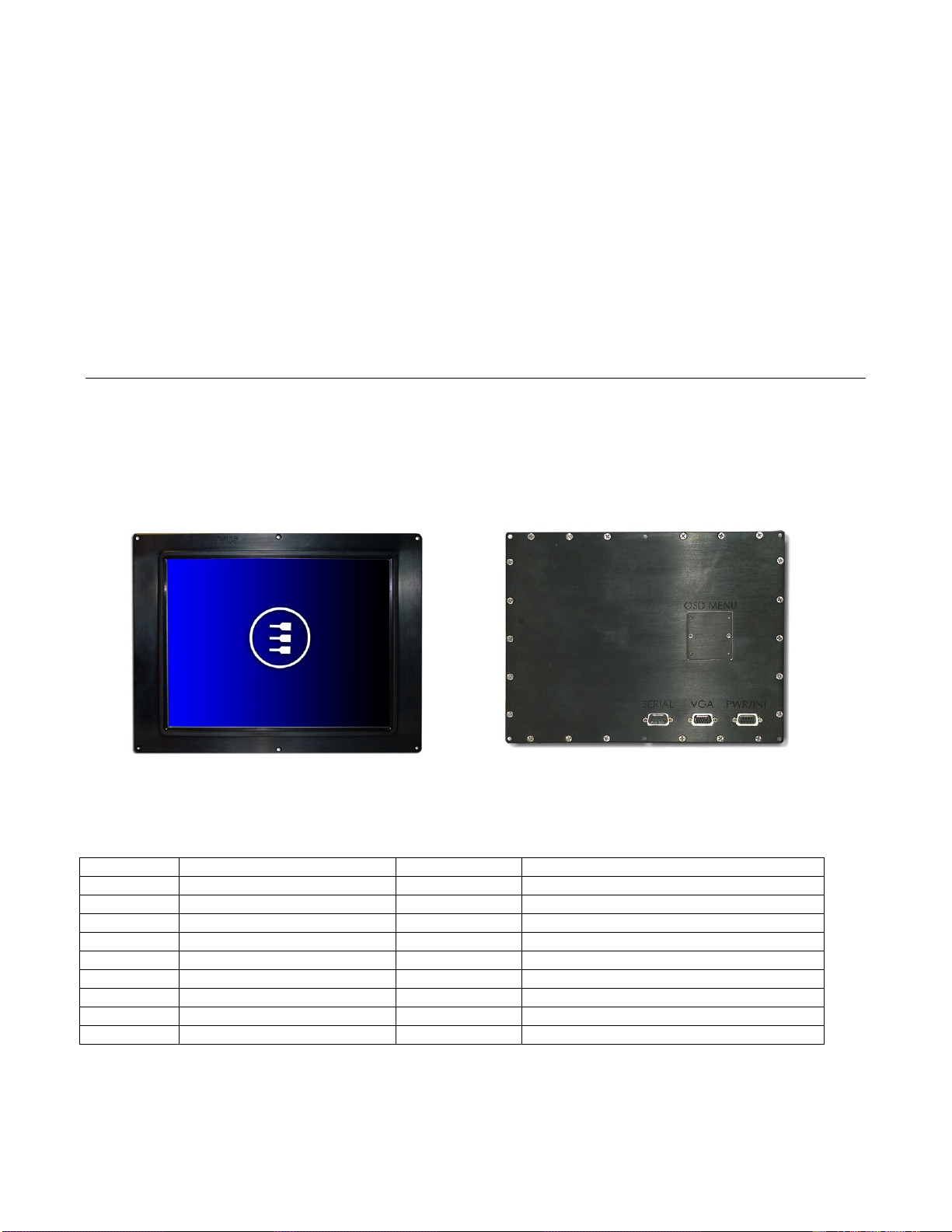
The DuraVIS 3400 is a rugged 10.4" resistive touch screen flat panel display optimized for panel-mount
installations in ships, aircraft, and ground vehicles. Its 400 Nit SVGA (800x600) resolution color Liquid Crystal
Display is built into a robust mechanical design with internal shock and vibration isolation, hardened aluminum
housing, and integrated gaskets for water and EMI resistance.

DuraVIS-3400 9
Product Definition
Panel Type: 10.39" Diagonal TFT-LCD with CCFL Backlight
Touch screen: Resistive Film Touch screen Overlay and RS-232 Controller
Viewable Area: 211.2mm (W) x 158.4mm (H)
Resolution: SVGA (800x600 pixels)
Contrast Ratio: 500:1 (typical)
Number of Colors: 260,000
Response Time: 30ms (typical) black to white; 10ms (typical) white to black
Luminance: 400 cd/m² (nit) typical
Video Input: Standard VGA Video Input, 800x600
Viewing Angle: 160 degree conical (-70~70° (H), -60~50° (V))
Power Input: Input: 9-36VDC (12-28V nominal)
Vibe Isolation: Internal Silastic Boot for Shock & Vibration Isolation
Material/Finish: 6061T6 Aluminum, Black Anodized Hardened Finish
Surface Treatments: Anti-Glare and ITO Hard Coating 3H
Operating Temp: -20°C to +60°C (-4°F to +140°F)
Storage Temp: -20°C to +80°C (-4°F to +176°F)
Weight: Approx. 7.5 Lbs (3.4 Kg)
Options: External protective boot for added handling protection in mobile applications.
External brightness control unit on the power cable to adjust brightness
externally.
MNL-0545B-01
Chapter 2 Connector Descriptions
The DuraVIS 3400 is equipped with two DB9 connectors and one DB15 connector. The male DB9 port is used
as an RS-232 interface for touch screen control. The VGA connector serves as the video input to the display and
the female DB9 connector is used for power input.
Front View Rear View
DB9 Male (Serial)
Pin Number Signal Name Input / Output Comment
1 N/C
2 Rx Input Receive
3 Tx Input Transmit
4 N/C
5 GND Input Ground
6 N/C
7 N/C
8 N/C
9 N/C
Table of contents
Other Parvus Adapter manuals


