Patlite WD PRO Series User manual

Notice to Customer
Thank for your purchasing our PATLITE products.
The WDB-D80S-PRO and WDT-6LR-Z2-PRO are WD
PRO Series products. For the WDR-LE-Z2, refer to ☞
"WDT-5LR-Z2/WDT-6LR-Z2 Instruction Manual."
●Request the installation and wiring be performed
by a professional contractor if construction work is
involved.
●Prior to installation, read this manual thoroughly
before using this product to ensure correct use.
●Re-read this manual before conducting maintenance,
inspections, repairs, and so on. If you have any
questions about this product, please contact our
service and repair desk.
●When using the system operation software WDS-
WIN01, use version 1.03 or later.
To the Contractor
●Prior to installation, read this manual thoroughly to
ensure it is installed correctly.
●Return this manual to the customer.
Wireless Data Communication System
WD PRO Series
TYPE WDB-D80S-PRO
TYPE
WDT-6LR-Z2-PRO
Instruction Manual
[Web Version]
Page
1. Before you begin
5
2. Contents
9
3. Models
10
4. Part Names and Dimensions
11
5. Operation Overview
12
6. Installation
18
7. Operation
25
8. Function Details
45
9. Troubleshooting
58
10.Specications
60
11. Replacement and Optional Parts
63
GA0000937_02

2
Wireless Data Communication System - WD PRO Series Instruction Manual
1. Before you begin __________________________________
5
1.1 About Safety Symbols …………………………………………………………………………………………………… 5
1.2 Safety Precautions ……………………………………………………………………………………………………… 6
2. Contents _____________________________________
9
2.1 About the Contents ……………………………………………………………………………………………………… 9
2.1.1 WDB-D80S-PRO (Contact Input - Serial Communication Base Unit) ………………………………………………… 9
2.1.2 WDT-6LR-Z2-PRO (WD PRO Transmitter) ………………………………………………………………………… 9
3. Models ____________________________________
10
3.1 About Models…………………………………………………………………………………………………………… 10
3.1.1 WDB-D80S-PRO (Contact Input - Serial Communication Base Unit) ……………………………………………… 10
3.1.2 WDT-6LR-Z2-PRO (WD PRO Transmitter) ……………………………………………………………………… 10
4. Part Names and Dimensions ____________________________
11
4.1 About Part Names and Dimensions …………………………………………………………………………………… 11
4.1.1 WDB-D80S-PRO (Contact Input - Serial Communication Base Unit) ……………………………………………… 11
4.1.2 WDT-6LR-Z2-PRO (WD PRO Transmitter) ……………………………………………………………………… 11
5. Operation Overview ________________________________
12
5.1 About the WD System ………………………………………………………………………………………………… 12
5.2SystemConguration ………………………………………………………………………………………………… 12
5.2.1 Glossary ………………………………………………………………………………………………………… 12
5.2.2SystemConguration …………………………………………………………………………………………… 13
5.2.2.1WDSystemCongurationatRunTime ………………………………………………………………………… 13
5.2.2.2WDSystemCongurationatMaintenance ……………………………………………………………………… 14
5.3 WD System Operation Overview ……………………………………………………………………………………… 15
5.4 About Visualization Application Software ……………………………………………………………………………… 15
5.4.1 CSV Data ……………………………………………………………………………………………………… 15
5.4.2 Socket Communication ………………………………………………………………………………………… 15
5.5 Function List …………………………………………………………………………………………………………… 16
5.5.1 LED Unit and Buzzer Unit Control Functions ……………………………………………………………………… 16
5.5.2 Contact Input Line Functions …………………………………………………………………………………… 16
5.5.3 RS-232C Communication Functions ……………………………………………………………………………… 16
5.5.4 Wireless Data Communication Function ………………………………………………………………………… 17
6. Installation ___________________________________
18
6.1 Before Installation ……………………………………………………………………………………………………… 18
6.1.1 What is the WD Wireless Network? ……………………………………………………………………………… 18
6.1.1.1 About the WD Wireless Network ……………………………………………………………………………… 18
6.1.1.2 About Selecting a Wireless Channel …………………………………………………………………………… 18
6.1.1.3 Example Wireless Channel Selection…………………………………………………………………………… 18
Table of Contents

3
Wireless Data Communication System - WD PRO Series Instruction Manual
6.1.2 About Grouping and ExtendedPanID …………………………………………………………………………… 19
6.1.3 About the MAC Address ………………………………………………………………………………………… 20
6.1.4 How many WDT you can connect to WDR ……………………………………………………………………… 20
6.2 About the Installation Environment …………………………………………………………………………………… 20
6.2.1 Installation Environment Main Points …………………………………………………………………………… 20
6.2.2AbouttheInuenceofSurroundingRadioWaves ………………………………………………………………… 21
6.2.3 Distance Between Devices ……………………………………………………………………………………… 22
6.2.4 Ensuring Line of Sight …………………………………………………………………………………………… 22
6.2.5 WDR Installation Position and Obstacles ………………………………………………………………………… 22
6.2.6.About the Signal Tower Power Supply Status …………………………………………………………………… 22
6.3 Equipment Settings …………………………………………………………………………………………………… 23
6.3.1 Setup Information ……………………………………………………………………………………………… 23
6.3.2 Equipment Settings ……………………………………………………………………………………………… 24
6.4 Equipment Installation ………………………………………………………………………………………………… 24
6.4.1 WDB-D80S, WDT-PRO Installation ……………………………………………………………………………… 24
6.4.2 Checking Connections to WDR ………………………………………………………………………………… 24
7. Operation ___________________________________
25
7.1 WDB-D80S Installation ………………………………………………………………………………………………… 25
7.1.1 Installing and Removing WDB-D80S……………………………………………………………………………… 25
7.1.1.1 Wiring RS-232C Cable from Bottom of Main Unit ……………………………………………………………… 27
7.1.1.2 Wiring RS-232C Cable from Cable Gland ……………………………………………………………………… 28
7.1.1.3 When Not Using the RS-232C Cable …………………………………………………………………………… 29
7.1.1.4 Wiring Method When Using Pole Bracket and Pole (Accessories) ……………………………………………… 30
7.1.2ReplacingMountingBolts(M4→M3)ontheMainUnit…………………………………………………………… 31
7.1.3 Detaching the Terminal Block Connector ………………………………………………………………………… 31
7.1.4 WDB-DB0S wiring ……………………………………………………………………………………………… 32
7.1.4.1 Wiring When Lighting Control and External Input, and Clear Input Control are on Different Equipment …………… 32
7.1.4.2 Wiring When Lighting Control and External Input, and Clear Input Control are on Different Equipment …………… 34
7.1.4.3 Terminal Block Connector (RS-232C Interface) Wiring ………………………………………………………… 35
7.2 WDT-PRO Installation ………………………………………………………………………………………………… 36
7.2.1 Installing and Removing WDT-PRO ……………………………………………………………………………… 36
7.2.1.1 Installing and Removing WDB-D80S …………………………………………………………………………… 36
7.2.1.2 Attaching the LED Unit and Buzzer Unit ………………………………………………………………………… 37
7.3 Using WDB-D80S, WDT-PRO ………………………………………………………………………………………… 39
7.3.1 Setting up WDB-D80S, WDT-PRO Main Unit……………………………………………………………………… 39
7.3.1.1 Setting up the Main Unit ……………………………………………………………………………………… 39
7.3.1.2 Setup Items …………………………………………………………………………………………………… 39
7.3.1.3 Required Equipment …………………………………………………………………………………………… 40
7.3.2 WDB-D80S DIP Switch Operations ……………………………………………………………………………… 40
7.3.3 Checking the WDB-D80S Status Lamp …………………………………………………………………………… 41
7.3.4 Checking Operations with WDT-PRO Indicator …………………………………………………………………… 42
7.3.5 Initializing WDB-D80S, WDT-PRO ……………………………………………………………………………… 43

4
Wireless Data Communication System - WD PRO Series Instruction Manual
7.3.6 Differences with WDT-LR Setup Items …………………………………………………………………………… 44
8. Function Details _________________________________
45
8.1 LED Unit and Buzzer Unit Control Functions ………………………………………………………………………… 45
8.1.1.Signal Tower Control Functions ………………………………………………………………………………… 45
8.1.2 Remote Control Functions ……………………………………………………………………………………… 46
8.1.3 Release Remote Control Function ……………………………………………………………………………… 47
8.2 Contact Input Line Functions ………………………………………………………………………………………… 48
8.2.1 Determine Signal Tower Control Input Function …………………………………………………………………… 48
8.2.2 Determine External Input Line Function ………………………………………………………………………… 50
8.2.3
Function to Determine Simultaneous Input of Signal Tower Control Line and External Input Line
……………………… 51
8.2.4 Determine Clear Input Line Function……………………………………………………………………………… 51
8.2.5 Simple Counter Function ………………………………………………………………………………………… 52
8.3 RS-232C Communication Functions ………………………………………………………………………………… 53
8.3.1 Communication Setup Function ………………………………………………………………………………… 53
8.3.2 Receive Data Function…………………………………………………………………………………………… 53
8.3.3 Data Transmission Function……………………………………………………………………………………… 54
8.4 Wireless Data Communication Functions……………………………………………………………………………… 54
8.4.1 Mesh Network Transmission …………………………………………………………………………………… 54
8.4.2 Information Transmission Function ……………………………………………………………………………… 55
8.4.2.1 About Timing of Input Information Transmissions ……………………………………………………………… 55
8.4.2.2 About Periodic Transmissions ………………………………………………………………………………… 55
8.4.2.3 About Information Transmitted to WDR ………………………………………………………………………… 55
8.4.2.4 About Format of Information Transmitted to WDR ……………………………………………………………… 56
8.4.2.5 About WDT-LR Format ………………………………………………………………………………………… 56
8.4.3 Retentive Status Function ……………………………………………………………………………………… 57
8.4.4 Receive Information Function …………………………………………………………………………………… 57
9. Troubleshooting _________________________________
58
9.1 Troubleshooting………………………………………………………………………………………………………… 58
9.1.1 Contact Input - Serial Communication Base Unit ………………………………………………………………… 58
9.1.2 WDT-6LR-Z2-PRO (WD PRO Transmitter) ……………………………………………………………………… 59
10.Specications _________________________________
60
10.1.Specications ………………………………………………………………………………………………………… 60
10.1.1 Contact Input - Serial Communication Base Unit ………………………………………………………………… 60
10.1.2 WD-PRO (WD PRO Transmitter) ……………………………………………………………………………… 62
11. Replacement and Optional Parts ___________________________
63
11.1 Replacement Parts …………………………………………………………………………………………………… 63
11.2 Optional Parts ………………………………………………………………………………………………………… 63
5
Wireless Data Communication System - WD PRO Series Instruction Manual 1. Before you begin
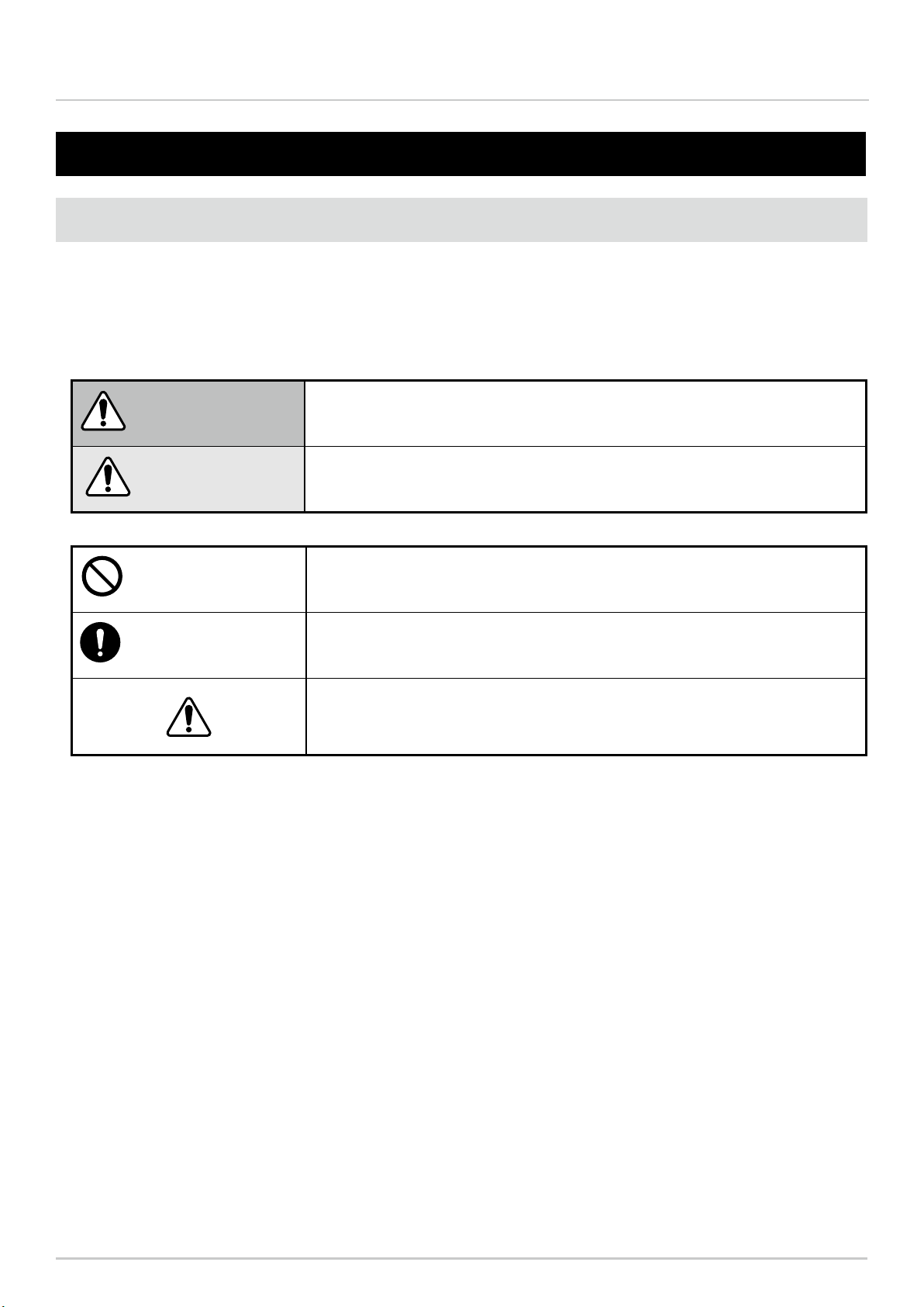
1.1 About Safety Symbols
To prevent injuries to the user and other personnel, as well as to prevent damage to assets, note the following:
●The following symbols classify warnings and cautions, and describe the level of harm and damage that will occur
when the corresponding instructions are ignored.
WARNING This symbol indicates, "Failure to follow the instructions may lead to
death or serious injury."
CAUTION This symbol indicates, "Failure to follow the instructions may lead to
injury or property damage."
Prohibited This symbol identifies "Prohibited" operations that should never be
carried out.
Mandatory This symbol identies "Mandatory" instructions that should always be
carried out.
This symbol identies general "Caution" related information.
●The following symbols classify and describe the content of associated messages.
1. Before you begin

6
Wireless Data Communication System - WD PRO Series Instruction Manual 1. Before you begin
1.2 Safety Precautions
Prohibited
●This wireless data communication system (hereby referred to as "this product") gets various data
and wirelessly transfers this data from a transmitter to a receiver. Do not use this product for any
other purpose.
●Do not use this product in the vicinity of implanted cardiac pacemakers and other medical
equipment, as this product's radio waves may affect the performance of these devices.
●Do not use or install the receiver in locations where liquids such as water is present, oil will
splatter, or locations that are humid or dusty. Failure to follow these instructions could result in re,
electric shock or product failure.
●To prevent accidents, do not use this product other than for its intended purpose and do not run
operations or maintenance other than those described in this manual.
●This product is not intended for use where high reliability is required and where human life is
involved, such as medical equipment, atomic energy equipment and machinery, aviation and
aerospace, transportation, and control of other equipment. If this product is used for these
applications, we cannot be held responsible in the event of injury or property damage.
●Do not modify or disassemble this product. Failure to follow these instructions could result in re
or electric shock.
●Do not use this product when there is condensation. Failure to follow these instructions could
result in re or electric shock.
●Do not allow liquids to enter the receiver, and do not allow it to have contact with metallic objects.
Failure to follow these instructions could result in re or electric shock.
Mandatory
●Request the installation and wiring be performed by a professional contractor if construction work
is involved. Failure to follow this instruction could result in re, electric shock or falls.
●Turn off the power before performing any electric wiring or product installation. Failure to follow
this instruction could result in electric shock.
●Always use a power supply within the operating voltage range. Failure to follow this instruction
could result in re or product failure.
●In places such as aircraft and hospitals, turn off this product where usage of wireless devices is
prohibited and where its radio waves affect surrounding equipment.
●We cannot foresee all circumstances concerning the handling and dangers associated with this
product. Therefore, not every possible danger is indicated in this instruction manual. To prevent
accidents when operating or maintaining the product, in addition to the safety guidelines identied
in the instructions of this manual, follow all general safety guidelines.
●In the unlikely event that there is an abnormal situation such as smoke or odors emitting from the
product, immediately cut the power supplied to the product. Failure to follow this instruction could
result in re or electric shock.
●Take the following precautions to prevent electric shock, short-circuit, or damage.
・
Disconnect the power before wiring, repairs, or replacing a fuse.
・Use this product under suitable conditions. If the body or unit becomes damaged, replace it.
WARNING

7
Wireless Data Communication System - WD PRO Series Instruction Manual 1. Before you begin
Prohibited
●Do not install this product near other electrical appliances. If you install this product near a facsimile,
personal computer, television, microwave oven, or equipment using a motor, this product may not operate
properly.
●Do not use this product with the O-ring or waterproof gasket removed. This will lower waterproong
performance. Failure to follow this instruction could result in product failure.
●Do not use this product in applications that require a high-degree of reliability or real-time performance. If
there are communication problems, this product cannot retrieve accurate data.
●Do not use this product near re, in hot or humid environments, or where corrosive or ammable gas is
present. Failure to follow this instruction could result in product malfunction.
●Do not use or store this product in the following locations. Failure to follow this instruction could result in
product malfunction or failure.
・Environments with poor breathability and ventilation.
・Near equipment that generate strong electrical or strong magnetic elds.
・Places exposed to direct sunlight.
・Locations subject to shock and vibration.
・Near heating appliances.
・Environments where there is dust or iron powder.
・Locations where the product may fall and break.
・Locations exposed to salty sea air.
●Attach the cap (included) to the cable gland. Waterproong performance is lowered if the cap is not
attached. Failure to follow this instruction could result in product failure.
●When the RS-232C cable is not passed through the cable gland, attach the sealing plug (included).
Waterproong performance is lowered if the sealing plug is not attached. Failure to follow this instruction
could result in product failure.
●Do not touch the connector terminals inside the unit when attaching or removing each unit or head cover.
Failure to follow this instruction could result in product failure.
●Do not apply voltage to the ashing common line or external input common line. Failure to follow this
instruction will result in product failure.
Mandatory
●Operate this product only after thorough testing in the customer environment.
●Pay close attention to the polarity of the power supply before connection. Connecting the power supply
incorrectly could result in product failure.
●To clean this product, wipe with a soft cloth dampened with water. Do not wipe with cleaners containing
thinners, benzine, gasoline, or oil.
●To maintain dust and waterproong performance, always use this product with the transmitter, LED unit,
and head cover or buzzer unit securely attached.
●When removing covers or packing, which are attached to this product, be careful not to snag the product.
Failure to follow this instruction could result in product failure.
CAUTION

8
Wireless Data Communication System - WD PRO Series Instruction Manual 1. Before you begin
●Although this product has a high level of security, there is the potential for third-parties to intercept
communications as this product uses radio waves.
●When using this product, pay close attention to the following:
・Due to the nature of radio waves, communication can be disabled even over insignicant distances as a
result of noise or other environmental factors.
・Do not use this product near chemicals. This product could melt or become deformed if any chemicals
adhere to it.
・To prevent static electricity, discharge the static electrical charge in your body before starting work. (You
can discharge static electricity by touching your hand on grounded metal objects.)
・Perform daily inspections.
・As a precaution, use this product in conjunction with other equipment to handle potential problems.
●Operation under the following conditions could cause the wireless communication distance to become
shorter than specied, and increase reaction times:
・Metal obstructions, such as steel doors or reinforced concrete, are between the transmitter and receiver.
・Transmitter or receiver is mounted on a metal surface.
・Powerful radio waves are nearby, such as those emitted by broadcasting stations.
・Power lines or other high-voltage lines are nearby.
●About the Operating Environment
・We tested the product with out of the box computers in a normal operating environment. However,
depending on your operating environment, which includes the computer main unit, peripheral devices and
applications in use, there may be cases where this product will not run properly.
●The software copyrights are held by our company. Do not use this software in other products, or duplicate
or modify a portion or all the software without prior written permission.
●Disposing this product
・When disposing of this product, follow the rules and regulations on how to handle recyclable materials as
outlined in your community.
●About this manual
・The contents of this manual are subject to change without notice.
・Images in this manual are for illustration purposes only, and may appear different from the actual product.
Additionally, for ease of explanation, the illustration may hide a portion of the product.
・This manual is copyrighted. No part of the manual, including drawings or technical information, can be
copied or duplicated in any manner, without prior consent.
・When transferring ownership of this product, include the instruction manual (digest version).
・If you have any questions or need further information, contact your nearest PATLITE sales representative.
CAUTION
・We cannot warrant against breakdowns caused by disassembling this product, natural disasters, or handling of this product that
is contrary to any warnings or precautions contained herein. Avoid using this product in ways other than those described in this
manual.
・We cannot be held responsible for damages and injuries caused by failing to pay attention, or failing to follow precautions, during
operation and maintenance.
9
Wireless Data Communication System - WD PRO Series Instruction Manual 2. Contents
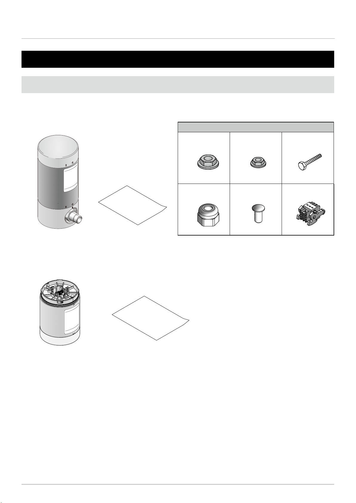
Accessories
Accessories
Accessories
2.1 About the Contents
2.1.1 WDB-D80S-PRO (Contact Input - Serial Communication Base Unit)
2.1.2 WDT-6LR-Z2-PRO (WD PRO Transmitter)
2. Contents
Main Unit: 1
Instruction Manual
(digest version): 1 copy
Instruction Manual (digest version): 1 copy
Main Unit: 1
Accessories
Hexagon Nut with
Flange (M4)
Hexagon Nut with
Flange (M3) Hexagon Bolt (M3)
Accessories
Accessories
Accessories
363
Cap for Cable Gland Sealing Plug for
Cable Gland
Terminal Block
Connector
Accessories
Accessories
Accessories
111
10
Wireless Data Communication System - WD PRO Series Instruction Manual 3. Models
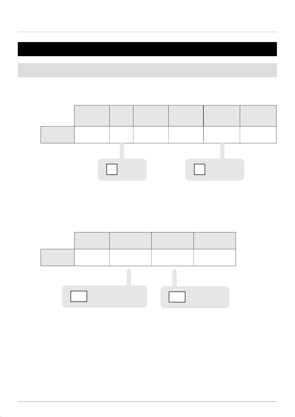
3.1 About Models
3.1.1 WDB-D80S-PRO (Contact Input - Serial Communication Base Unit)
3.1.2 WDT-6LR-Z2-PRO (WD PRO Transmitter)
3. Models
Model Format
Number of
External Contact
Inputs
Number of
External Contact
Outputs
Communication Series
Model Number WDB- D 8 0 S -PRO
Digital
DSerial
communication
S
Model Size Wireless Type Series
Model Number WDT- 6LR- Z2 -PRO
φ60 LR Signal Tower
6LR Zigbee2007Pro
2.4GHz
Z2
11
Wireless Data Communication System - WD PRO Series Instruction Manual 4. Part Names and Dimensions
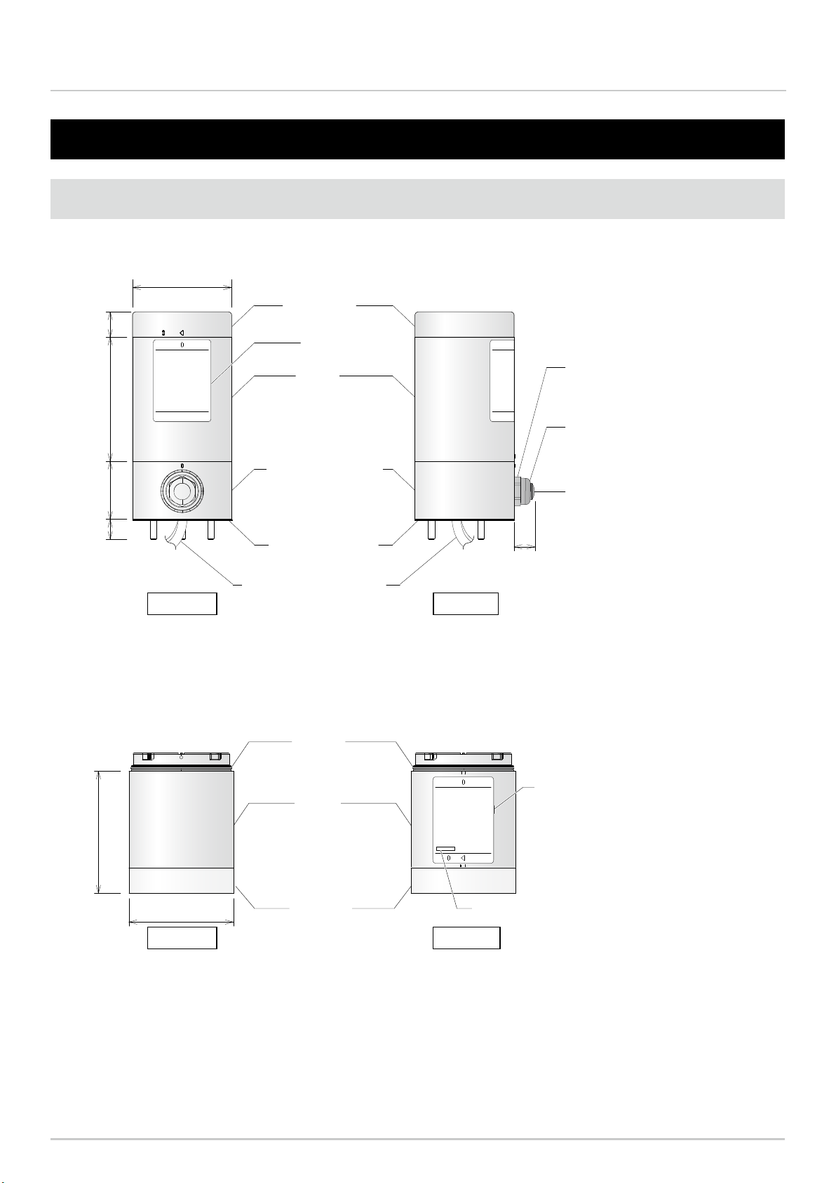
4.1 About Part Names and Dimensions
4.1.1 WDB-D80S-PRO (Contact Input - Serial Communication Base Unit)
4.1.2 WDT-6LR-Z2-PRO (WD PRO Transmitter)
φ60
φ60
O ring
MAC Address
Case
Indicator
75
19
35
12
(12)
Cable gland
Cap for cable gland
(accessory)
Sealing plug for cable gland
(accessory)
Head cover
Body
Direct Mount Bracket
Waterproof gasket
70
Nameplate
Nameplate
Lead Wire ULI061 AWG24
(Wire length: 1300 mm)
4. Part Names and Dimensions
φ60
φ60
O ring
MAC Address
Case
Indicator
75
19
35
12
(12)
Cable gland
Cap for cable gland
(accessory)
Sealing plug for cable gland
(accessory)
Head cover
Body
Direct Mount Bracket
Waterproof gasket
70
Nameplate
Nameplate
Lead Wire ULI061 AWG24
(Wire length: 1300 mm)
(Unit: mm)
(Unit: mm)
Front View Rear View
Side ViewFront View

12
Wireless Data Communication System - WD PRO Series Instruction Manual 5. Operation Overview
5.1 About the WD System
To collect data available on equipment in your facility, the WD system transmits associated information (such as
equipment operation data) to a host computer over the WD wireless network. By using visualization application
software, you can use collected information to accurately view the capacity utilization rate, trigger improvement
activities, and optimize operations. This application is not limited to production facilities and can be applied to other
areas.
5.2 System Conguration
5.2.1 Glossary
Term Description
WD System Name for the system as a whole. Can include multiple WD wireless networks and the host.
WD Wireless Network A part of the wireless network that consists of one WDR and multiple WDT (up to 30 units).
WDR
Receiver on a WD wireless network. Receives information from multiple WDT and transmits
to the host.
Model: WDR-LE-Z2
WDS
Application software for WDT and WDR settings, and for collecting Signal Tower information
in the WD system as CSV log data.
Model: WDS-WIN01
WDT
Transmitter on a WD wireless network. Collects various information from a Signal Tower and
transmits the information wirelessly to WDR.
Models: WDT-5E-Z2, WDT-6M-Z2, WDT-5LR-Z2, WDT-6LR-Z2, WDT-6LR-Z2-PRO
WDT-LR
Transmitter on a WD wireless network. Connect and use with LR Signal Towers.
Models: WDT-5LR-Z2, WDT-6LR-Z2
WDT-PRO
WD PRO transmitter on a WD wireless network. Information retrieved from a WD PRO
Series Base Unit is wirelessly transmitted to WDR.
Model: WDT-6LR-Z2-PRO
WDB-D80S
Contact Input - Serial Communication Base Unit on the WD wireless network. Transmits
the status of the Signal Tower control line, status of the external input line, and serial
communication data to WDT-PRO.
Model: WDB-D80S-PRO
Signal Tower Input Information Input information of the Signal Tower collected by the WD system.
Host Equipment for operation of the WD system.
Visualization
Application Software*
Application software installed on the host PC. Use this application to display information
collected by the WD system in a gantt chart or graph. Must be provided by the customer.
Maintenance PC At maintenance, personal computer for setting up the WDT, WDT-PRO, WDB-D80S, and
WDR.
*For visualization application software, refer to “5.4 About Visualization Application Software(☞P.15)”.
5. Operation Overview
13
Wireless Data Communication System - WD PRO Series Instruction Manual 5. Operation Overview
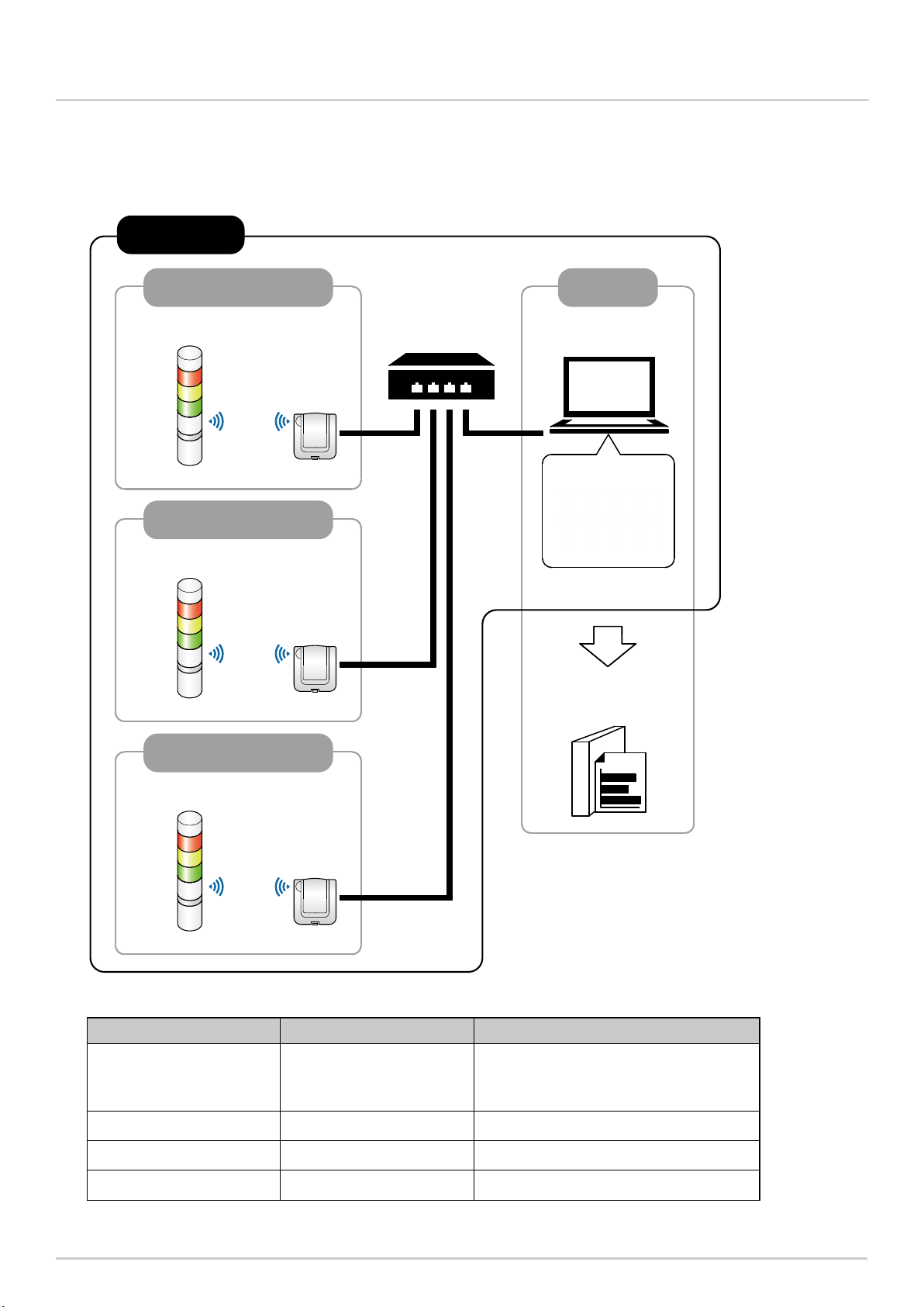
5.2.2 System Conguration
5.2.2.1 WD System Conguration at Run Time
●Conguration diagram
● Conguration
Item Number of conguration items Models
WDT 1 to 30 units*1per receiver
WDT-5E-Z2/WDT-6M-Z2/WDT-5LR-Z2/
WDT-6LR-Z2/WDT-6LR-Z2-PRO (this
product)
WDR 1 to 20 units*2WDR-LE-Z2
WDS 1 WDS-WIN01 *Version 1.03 or later
Host PC*31 unit -
*1 For information, refer to “6.1.4 How many WDT you can connect to WDR(☞P.20)”.
*2 When collecting CSV log data with WDS-WIN01.
*3 When connecting the WDR directly to the host PC with a LAN cable, use a cross cable.
WDT (maximum 30 units)
WDR
WDS
Visualization
Application
LAN
WD wireless network
Host PC
WDT (maximum 30 units)
WDR
WD wireless network
WDT (maximum 30 units)
WDR
WD wireless network
WD System

14
Wireless Data Communication System - WD PRO Series Instruction Manual 5. Operation Overview
● Conguration
Item Number of conguration items Models
WDT-PRO
Units as required
WDT-6LR-Z2-PRO
WDB-D80S WDB-D80S-PRO
WDR 1 unit WDR-LE-Z2
WDS 1 WDS-WIN01 *Version 1.03 or later
Maintenance PC 1 unit -
LAN Cable*1 *21 -
USB Cable*3 *41 -
micro-USB Cable*3 *51 -
* 1 When conguring the WDR LAN settings, connect with a LAN cable.
* 2 When connecting the WDR directly to the host PC with a LAN cable, use a cross cable.
* 3 Use USB and micro-USB cables that are 3m or shorter.
* 4 Do not connect LAN and USB cables at the same time.
* 5 Use the micro-USB cable with this product's power supply only. The USB driver may be installed on the maintenance PC,
but this is not an issue.
5.2.2.2 WD System Conguration at Maintenance
●Conguration diagram
WDR
micro-USB
Connector Socket
Bottom
WDS
LAN (Cross Cable) or
USB Cable
micro-USB Cable
AC Adaptor (option)
(This Product)
*Only when connecting
to the LAN, connect
supplied AC adaptor
Maintenance PC
WDT-PRO / WDB-D80S
WD System
WARNING
When using a USB connection between this product and a computer, do not let the product's power supply contact the
computer or peripheral devices.
Failure to follow this instruction could result in burns and ignite the product. For example, when grounding the positive
terminal of this product's power supply, do not frame ground the computer, which is connected to this product via
USB. Depending on the computer, some negative terminals on the USB port are attached to the connector's outer
shell. When such a computer is connected to this product, the computer's FG (housing) and negative terminal of this
product's USB port are connected. In this state, if the computer is attached to the metal portions where the positive
terminal of this product's power supply is grounded, 24 V will be applied to this product's negative terminal on the USB
port, which will lead to re.
15
Wireless Data Communication System - WD PRO Series Instruction Manual 5. Operation Overview
CAUTION
The customer needs to provide the visualization application software.
Select a visualization application software suitable for customer visualization requirements.
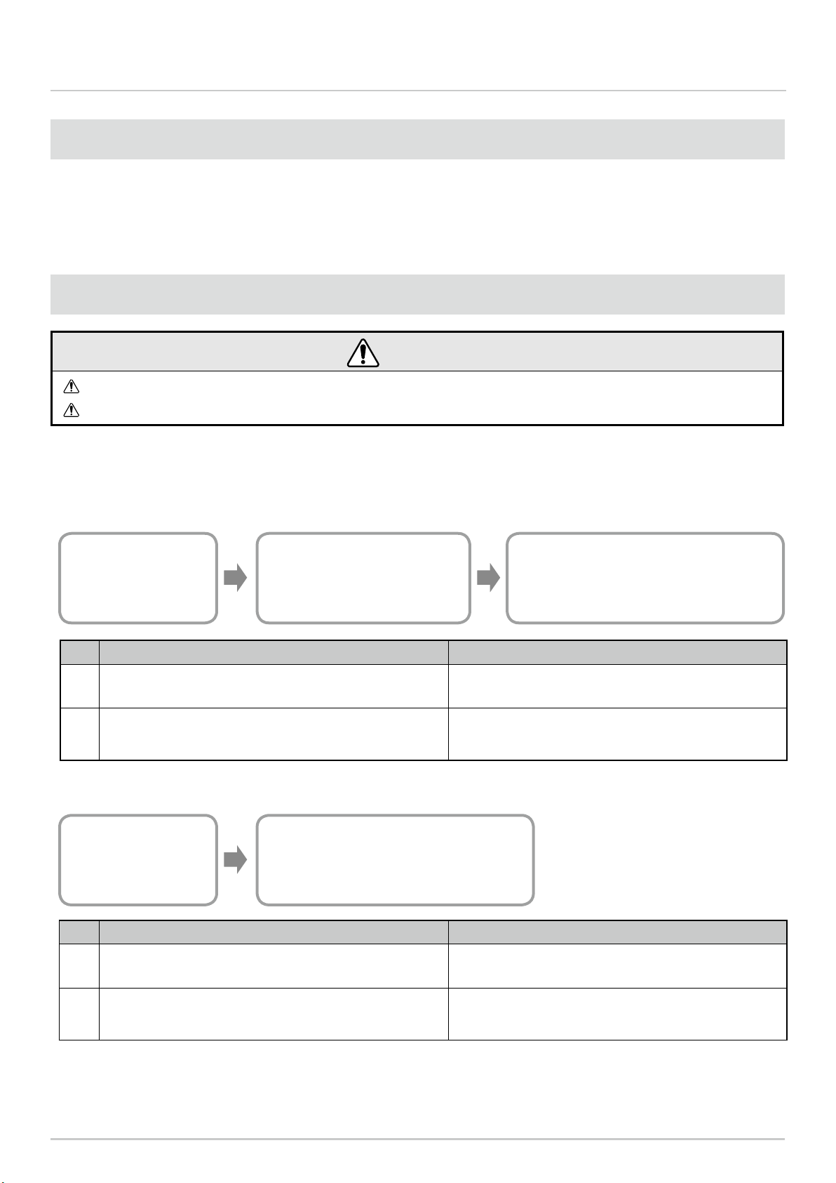
5.4 About Visualization Application Software
There are two ways the WD system passes collected information to the visualization application software:
1) CSV Data 2) Socket Communication.
5.4.1 CSV Data
WD System
Transmit Signal Tower
information
WDS
Read Signal Tower Input Information
and save as CSV Data
Visualization Application Software
Visualization of CSV Data
No. Visualization Application Software Preparation References
1When using software packages from PATLITE partners that
support the WD system ☞ Please contact our sales ofce.
2When customer develops their own solution
Refer to ☞ this manual
Refer to ☞ "WDS-WIN01 Instruction Manual"
No. Visualization Application Software Preparation References
1When using software packages from PATLITE partners that
support the WD system ☞ Please contact our sales ofce.
2When customer develops their own solution
Refer to ☞ this manual
Refer to ☞ "Application Notes"*
* For information, contact your nearest PATLITE sales representative.
5.4.2 Socket Communication
Visualization Application Software
Visualization of Signal Tower input information
WD System
Transmit Signal Tower
information
5.3 WD System Operation Overview
・WDT transmits Signal Tower information via the WDR to the WDS on the host PC.
・WDS collects the information and stores it as CSV log data. Load the data into visualization application software.
・The visualization application software can also directly load the WDR Signal Tower information.

16
Wireless Data Communication System - WD PRO Series Instruction Manual 5. Operation Overview
5.5 Function List
5.5.1 LED Unit and Buzzer Unit Control Functions
Runs control of LED and buzzer units connected to WDT-PRO. There are two types: Control based on the Signal
Tower control line, and remote control from the host.
Function Description References
Signal Tower Control
Functions
Functions that control LED or buzzer
units with the Signal Tower control line. ☞ 8.1.1.Signal Tower Control Functions(P.45)
Remote Control
Functions
Functions that perform remote control
of LED or buzzer units from the host. ☞ 8.1.2 Remote Control Functions(P.46)
Release Remote Control
Functions
Function that enables operation
transition from Remote Control
Function to Signal Tower Control
Function.
☞ 8.1.3 Release Remote Control Function(P.47)
5.5.2 Contact Input Line Functions
Determines the input status of the Signal Tower control line, external input line, and clear input line.
Function Description References
Determine Signal Tower
Control Input Function
Function for determining the signal
input status of the Signal Tower control
line.
☞ 8.2.1 Determine Signal Tower Control Input
Function(P.48)
Determine External Input
Line Function
Function to detect changes in state of
8 external input lines and to save that
information.
☞ 8.2.2 Determine External Input Line
Function(P.50)
Determine Simultaneous
Input Function
Function to set the sensitivity for
determining simultaneous input on the
Signal Tower control line and external
input line.
☞ 8.2.3 Function to Determine Simultaneous
Input of Signal Tower Control Line and
External Input Line(P.51)
Determine Clear Input
Line Function
Function to detect inputs on the clear
input line and to save that information.
Detects when the clear input line
changes from OFF to ON.
☞ 8.2.4 Determine Clear Input Line
Function(P.51)
Simple Counter Function
Function for saving the accumulated
value (counter value) of pulse inputs
(incremented 1 at a time) on a signal
wire.
☞ 8.2.5 Simple Counter Function(P.52)
5.5.3 RS-232C Communication Functions
Runs communication with external equipment, such as a bar code reader, through the RS-232C interface.
Function Description References
Communication Setup
Function
Function to set up RS-232C
communication. ☞ 8.3.1 Communication Setup Function(P.53)
Receive Data Function
Function for receiving data transmitted
by external equipment, following the
receive data le format settings.
☞ 8.3.2 Receive Data Function(P.53)
Transmit Data Function Function for transmitting to external
equipment data received from the host. ☞ 8.3.3 Data Transmission Function(P.54)

17
Wireless Data Communication System - WD PRO Series Instruction Manual 5. Operation Overview
5.5.4 Wireless Data Communication Function
Wirelessly transmits to WDR the status information of each contact input line or the RS-232C data input. Also
receives RS-232C data from the host and transmits to external equipment.
Function Description References
Mesh Network
Transmission Function
Function that automatically connects the
WDT over the optimum communication
route to the WDR for transmitting
information.
☞ 8.4.1 Mesh Network Transmission(P.54)
Transmit Information
Function
Function for WDT-PRO to wirelessly
transmit to WDR the Signal Tower control
line, external input line, data from RS-
232C communication, and counter value.
☞ 8.4.2 Information Transmission
Function(P.55)
Retentive Status
Function
When a transmission failure occurs
between the Signal Tower information
input and the actual transmission,
this function temporarily retains the
transmission information in the product.
☞ 8.4.3 Retentive Status Function(P.57)
Receive Information
Function
Function for the WDT-PRO to receive
commands and data wirelessly transmitted
from WDR.
☞ 8.4.4 Receive Information Function(P.57)

18
Wireless Data Communication System - WD PRO Series Instruction Manual 6. Installation
・The frequency of each channel on the WD wireless network is as follows.
Channel Mid-range frequency
(MHz) Bandwidth (MHz)
CH11 2,405 2
CH12 2,410 2
CH13 2,415 2
CH14 2,420 2
CH15 2,425 2
CH16 2,430 2
CH17 2,435 2
CH18 2,440 2
6.1 Before Installation
6.1.1 What is the WD Wireless Network?
6.1.1.1 About the WD Wireless Network
・The WD wireless network operates on the IEEE802.15.4 (ZigBee) compliant 2.4 GHz frequency. Although it
runs on the same 2.4 GHz frequency as a wireless LAN (Wi-Fi), because it conforms to IEEE802.15.4 the WD
wireless network can operate without a wireless LAN. However, if the frequencies you use overlap, the WD
wireless network could experience transmission delays and other communication issues.
・The wireless communication is encrypted. The encryption standard used is AES-CCM (Advanced Encryption
Standard-Counter with CBC-MAC), with an encryption key of 128 bits.
6.1.1.2 About Selecting a Wireless Channel
・The WD wireless network uses 16 wireless channels (CH11 to CH26).
・Select a wireless channel to avoid conict with the frequency band of the LAN wireless channels in your instal-
lation environment.
・The relationship between frequency bands of channels on the WD wireless network and on the wireless LAN is
as follows.
CH
11
CH
12
CH
13
CH
14
CH
15
CH
16
CH
17
CH
18
CH
19
CH
20
CH
21
CH
22
CH
23
CH
24
CH
25
CH
26
WD Wireless Network Channels in use
Wireless LAN Channels in use
CH1 CH6 CH11
CH2 CH7 CH12
CH3 CH8 CH13
CH4 CH9
CH5 CH10
2400 MHz 2500MHz
6. Installation
Channel Mid-range frequency
(MHz) Bandwidth (MHz)
CH19 2,445 2
CH20 2,450 2
CH21 2,455 2
CH22 2,460 2
CH23 2,465 2
CH24 2,470 2
CH25 2,475 2
CH26 2,480 2
6.1.1.3 Example Wireless Channel Selection
・
When the wireless LAN uses three channels (CH1, CH6, and CH11), select either CH15, CH20, CH25, or CH26.
・In most cases, selecting CH25 or CH26 will enable you to avoid the wireless LAN channels.

19
Wireless Data Communication System - WD PRO Series Instruction Manual 6. Installation
6.1.2 About Grouping and ExtendedPanID
・The WD system requires grouping each WD wireless network (one WDR with multiple connected WDT). You
can dene the group by setting the ExtendedPanID property on the WDR and WDT to the same value. The
ExtendedPanID consists of 16 single-byte, alphanumeric characters. Setup range: 0000 0000 0000 0000 to
FFFF FFFF FFFF FFFE.
・You can use any combination of WDT-5E-Z2, WDT-6M-Z2, WDT-5LR-Z2, and WDT-6LR-Z2.
・The following illustrate how you can set the ExtendedPanID and wireless channels for devices in multiple groups.
・If there are multiple channels available for selection, you should use separate wireless channels for each group. By
distributing groups over multiple channels, you can reduce the load concentrated on a single wireless channel.
WD Network
[WDT and WDR Common Settings]
・ExtendedPanID: 0000 0000 0000 0001
・Wireless Channel: CH15
Group 1
WD Network
[WDT and WDR Common Settings]
・ExtendedPanID: 0000 0000 0000 0003
・Wireless Channel: CH26
Group 3
WD Network
[WDT and WDR Common Settings]
・ExtendedPanID: 0000 0000 0000 0005
・Wireless Channel: CH20
Group 5
WD Network
[WDT and WDR Common Settings]
・ExtendedPanID: 0000 0000 0000 0002
・Wireless Channel: CH20
Group 2
WD Network
[WDT and WDR Common Settings]
・ExtendedPanID: 0000 0000 0000 0004
・Wireless Channel: CH15
Group 4
WD Network
[WDT and WDR Common Settings]
・ExtendedPanID: 0000 0000 0000 0006
・Wireless Channel: CH26
Group 6
CAUTION
When there are multiple WDR in your system, do not use duplicate ExtendedPanID values. The product may not operate
properly.
When the WDT ExtendedPanID is 0000 0000 0000 0000, regardless of the ExtendedPanID setting all the WDR may
be grouped together. In this scenario, because the grouped wireless network is not stable, set any value other than
0000 0000 0000 0000 during conguration.

20
Wireless Data Communication System - WD PRO Series Instruction Manual 6. Installation
6.1.3 About the MAC Address
・Static address assigned to WDT-PRO for identication. This address is called a MAC address (IEEE address).
・The MAC address is printed on a nameplate on the back of the WDT-PRO.
Nameplate
0123456789ABCDEF
PATLITE
Corporation
MADE IN JAPAN
01234
技術基準認証済
無線装置内蔵
2.4 DS 1
MAC Address
0123456789ABCDEF
6.1.4 How many WDT you can connect to WDR
The number of WDT units you can connect to a WDR is limited by the frequency of information sent to the WDR.
The total transmissions from all WDT connected to the WDR is limited to 120 or less per minute (transmission
interval of 0.5 seconds or longer). To satisfy this condition, use the following table as a guide and determine the
number of connected units.
WDT connection limit Estimated number of Contact Input Information, RS-232C Input Information,
and Clear Input Information transmissions / 1 WDT
30 unit 4 times per minute
20 unit 6 times per minute
10 unit 12 times per minute
5 unit 24 times per minute
1 unit 120 times per minute
6.2 About the Installation Environment
6.2.1 Installation Environment Main Points
There are ve essential points to consider at installation.
No. Description References
1There is no inuence in radio waves at the installation site. Also,
the radio waves at the installation site do not change over time.
☞ 6.2.2 About the Inuence of Surrounding
Radio Waves(P.21)
2
The distance between devices (WDR, WDT) does not exceed
recommendations. The recommended distance between all WDT
and WDR is within line of sight.
☞ 6.2.3 Distance Between Devices(P.22)
3
Each device (WDR and WDT) is in line of sight. To ensure good
line of sight, the location should not be cluttered and should be
free of any obstacles.
☞ 6.2.4 Ensuring Line of Sight(P.22)
4
WDR placement is appropriate.
・Install in a location as high as possible.
・Install away from obstacles that could disrupt radio waves.
☞ 6.2.5 WDR Installation Position and
Obstacles(P.22)
5
Each device is always powered, and the mesh network is always
available. If power is not available for one of the WDT, the
communication path could get interrupted and information may not
be transmitted.
-
This manual suits for next models
2
Table of contents


