Patton FiberPlex FP101EM User manual

1
FiberPlex™ Model FP101EM
Mini Industrial Gigabit Media Converter
User Manual
FCC MARKING
This Equipment has been tested and found to comply with the limits for a Class A digital device,
pursuant to part 15 of the FCC Rules. These limits are designed to provide reasonable protection
against harmful interference when the equipment is operated in a commercial environment.
This equipment generates, uses, and can radiate radio frequency energy and, if not installed and
used in accordance with the instruction manual, may cause harmful interference to radio
communications.
Operation of this equipment in a residential area is likely to cause harmful interference in which
case the user will be required to correct the interference at his own expense.
This device complies with Part 15 of the FCC Rules. Operation is subject to the following two
conditions: (1) this device may not cause harmful interference, and (2) this device must accept
any interference received; including interference that may cause undesired operation.
CE MARKING
This equipment complies with the requirements relating to electromagnetic compatibility, EN
55032/24 class A for ITE, the essential protection requirement of Council Directive 2014/30/EU
on the approximation of the laws of the Member States relating to electromagnetic compatibility.
Trademark Statement
The term FiberPlex is a trademark of Patton Electronics Company. All other trademarks presented in this
document are the property of their respective owners.
Copyright © 2016, Patton Electronics Company. All rights reserved.
The information in this document is subject to change without notice. Patton Electronics assumes no
liability for errors that may appear in this document.

2
Key Features
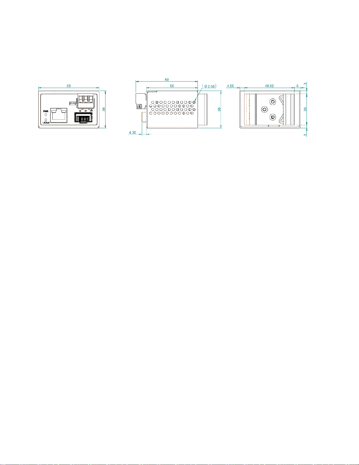
•True Mini, hardened design enclosure 59x36x50mm (LxWxD)
•Supports 12V-56VDC.
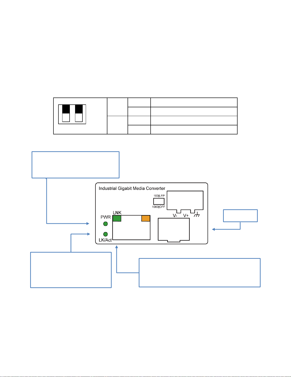
•Supports Link Fault Pass through (LFP) function
•Supports automatically Switch Mode and Converter Mode.
•Surge protector on power input.
•ESD protector on RJ-45 port
•Provides Far End Fault function on FX port.
•Provides increased Noise Immunity
•Extended environmental specification -40°C to 75°C
Introduction
Patton’s FP101EM converts singlemode or multimode fiber to a copper Ethernet signal. The increased
bandwidth and reliability is ideal for applications involving devices such as IP security cameras, VoIP
phones, wireless access points, POS kiosks, BACs, PLCs and many other remote networking needs.
Because Ethernet over Cat 5e/6 cables is limited to only 100 meters (328 feet), using fiber as a backhaul
allows for a massive increase in distances. SFP options for multimode can reach up to 2 km (1.24 miles),
and singlemode options can range as far as 120 km (74 miles). In addition to the reach, you get Fiber’s
superior immunity to noise and, harmful transients (surges).
The FP101EM is housed in an IP30-rated DIN-rail or wall-mount enabled enclosure, and has an operating
temperature of -40 to 75°C. Its rugged design and wide temperature range makes it an ideal media
converter for industrial or harsh environments. Its small size even allows you to put it inside the enclosures
of your primary devices.
The Fiberplex 101EM is very simple to use, completely plug and play. LEDs will make it clear when
power is detected on the power inputs.

3
Installation package
This unit can be din-rail mounted or wall-mounted. Din-rail brackets and wall-mount brackets are
included.
Power connection
This unit provides a 3-pin terminal block. The DC voltage range is from 12VDC to 56VDC. Always make
sure your input voltage is within this supported voltage range.
To connect power: Follow the printed polarity for V+, V- and Ground. Connect positive wire to V+,
connect negative wire to V- and also connect neutral wire to ground.
Power connecting procedure:
STEP 1 – Pull out 3 pin terminal block.
STEP 2 – Connect wire to V+, V- and Ground.
STEP 3 – Connect SFP fiber wire to fiber port.
STEP 4 – Plug back 3 pin terminal block to its place.
WARNING -- Always SHUT OFF power source to connect power wire.
WARNING -- DO NOT force SFP fiber into SFP housing without removing terminal block
WARNING -- Any exceeded input voltage will not make this unit function and may damage this
unit.

4
Dip switch function
This unit is equipped with dip switches, located on the front panel. Adjusting the dip switches will change
the default function of this unit. This unit has set to manufacturer default as: SFP speed 1000M and LFP
function OFF.
The table shown as you may change the dip switch setting to your desired environment.
LED indicator
DIP 1
UP
100M
DOWN
1000M (default)
DIP 2
UP
LFP enabled
DOWN
LFP disabled (default)
PWR (Green)
ON – Power is detected
OFF – Power is not detected
LK/Act (Green)
ON – Fiber port is detected
Flashing – Fiber data is
transmitting/receiving
TX (Green)
On – TX port is detected
Flashing – TX data is transmitting/receiving
Fiber Port
UP
DOWN
100|LFP
1000|OFF

5
Specification
IEEE Standard
IEEE 802.3 10Base-T Ethernet
IEEE 802.3u 100Base-TX Fast Ethernet
IEEE 802.3ab 1000Base-T Gigabit Ethernet
IEEE 802.3z 1000Base-X Gigabit Ethernet
IEEE 802.3x Flow Control and Back Pressure
Switch Architecture
Back-plane (Switching Fabric): 4Gbps
Data Processing
Ports speed are the same: Converter mode
Ports speed are not the same: Switch mode (store and
forward)
Flow Control:
IEEE 802.3x Flow Control and Back Pressure
Jumbo Frame
16KB
MAC address Table Size
1K
Packet Buffer Size
512Kbits
Network Connector:
1 x RJ-45 10/100/1000 Base-T(X)
Auto MDI/MDI-X function, Full/Half duplex
1 x 100/1000 Base-TX SFP
Network Cable
UTP/STP above Cat.5e Cable
EIA/TIA-568 10-ohm (100m)
Fiber Cable (Multi-mode):50/125um,62.5/125um
Fiber Cable (Single-mode): 9/125um
Protocol
CSMA/CD
LED
PWR (Green): ON-Power is detected
OFF-Power is not detected
SFP Lnk/Act (Green): ON-FX port is detected
Flashing-FX data is transmitting/receiving
RJ-45 port:
Lnk/Act (Green): ON-TX port is detected
Flashing-TX data is transmitting
DIP Switch
DIP 1: UP-SFP speed 100M
DOWN-SFP speed 1000M (Default)
DIP 2: UP-LFP enabled
DOWN-LFP disabled (Default)
Link Fault Pass Through (LFP) is when copper side signal
lost or disconnect, fiber side link signal will actively off,
when fiber side signal lost or disconnect, copper side link
signal will also actively off.
Reserve polarity protection
Present
Overload current protection
Present

6
Power Input
12V-56VDC
Power Consumption
1.92W full load without PoE at 48VDC
Removable Terminal Block
3 pin contact terminal block for power input
Wire range: 0.34mm^2 to 2.5mm^2
Solid wire (AWG):12-24/14-22
Stranded wire (AWG): 12-24/14-22
Torque:5lb-In/0.5Nm/0.56Nm
Wire Strip length: 7-8mm
Operating Temperature
-40°C to +75°C
Operating Humidity
5% to 95% (Non-condensing)
Storage Temperature
-40°C to 85°C
MTBF (mean time between failure)
574,276 hrs (Telcordia (Bellcore), GB) at 50°C
Housing
Rugged Metal, IP30 Protection
Case Dimension
59x36x49mm (LxWxD)
Installation
DIN Rail or Wall Mount options included
Certifications:
Safety
LVD(EN60950-1)
EMC
CE, FCC, EN 55032/24
EMI
CISPR 32, FCC Part 15B Class A
EMS
IEC 61000-4-2 ESD: Contact: 6KV; Air: 8KV
IEC 61000-4-4 EFT: Power: 2KV; Signal: 2KV
IEC 61000-4-5 Surge: Power: 2KV; Signal: 2KV
Vibration
EN 60068-2-6
Shock
EN 60068-2-27
Free Fall
EN 60068-2-32

7
Housing Dimension (mm)
NOTE:
Housing dimension is for the purpose of showing product Length, Width, Height, din-rail, and terminal
block’s position and dimension. Please reference the LED Indicator Page for correct port order.
Table of contents
Other Patton Media Converter manuals