Patton FiberPlex FP102EBT User manual

1
FiberPlex™ Model FP102EBT
Industrial 10 Gigabit Media Converter with 90W PoE Injector
User Manual
FCC MARKING
This Equipment has been tested and found to comply with the limits for a Class A digital device, pursuant
to part 15 of the FCC Rules. These limits are designed to provide reasonable protection against harmful
interference when the equipment is operated in a commercial environment. This equipment generates,
uses, and can radiate radio frequency energy and, if not installed and used in accordance with the
instruction manual, may cause harmful interference to radio communications.
Operation of this equipment in a residential area is likely to cause harmful interference in which case the
user will be required to correct the interference at his own expense.
This device complies with Part 15 of the FCC Rules. Operation is subject to the following two conditions:
(1) this device may not cause harmful interference, and (2) this device must accept any interference
received; including interference that may cause undesired operation.
CE MARKING
This equipment complies with the requirements relating to electromagnetic compatibility, EN 55032/24
class A for ITE, the essential protection requirement of Council Directive 2014/30/EU on the
approximation of the laws of the Member States relating to electromagnetic compatibility.
Trademark Statement
The term FiberPlex is a trademark of Patton Electronics Company. All other trademarks presented in this
document are the property of their respective owners.
Copyright © 2021, Patton Electronics Company. All rights reserved.
The information in this document is subject to change without notice. Patton Electronics assumes no
liability for errors that may appear in this document.

2
Key Features
•Hardened design enclosure
•Supports 52V-56VDC
•Supports automatically switch mode and converter mode
•Adjustable SFP speed 1G or 10G
•Surge protection on power input
•ESD protection on RJ-45 port
•Provides increased Noise Immunity
Introduction
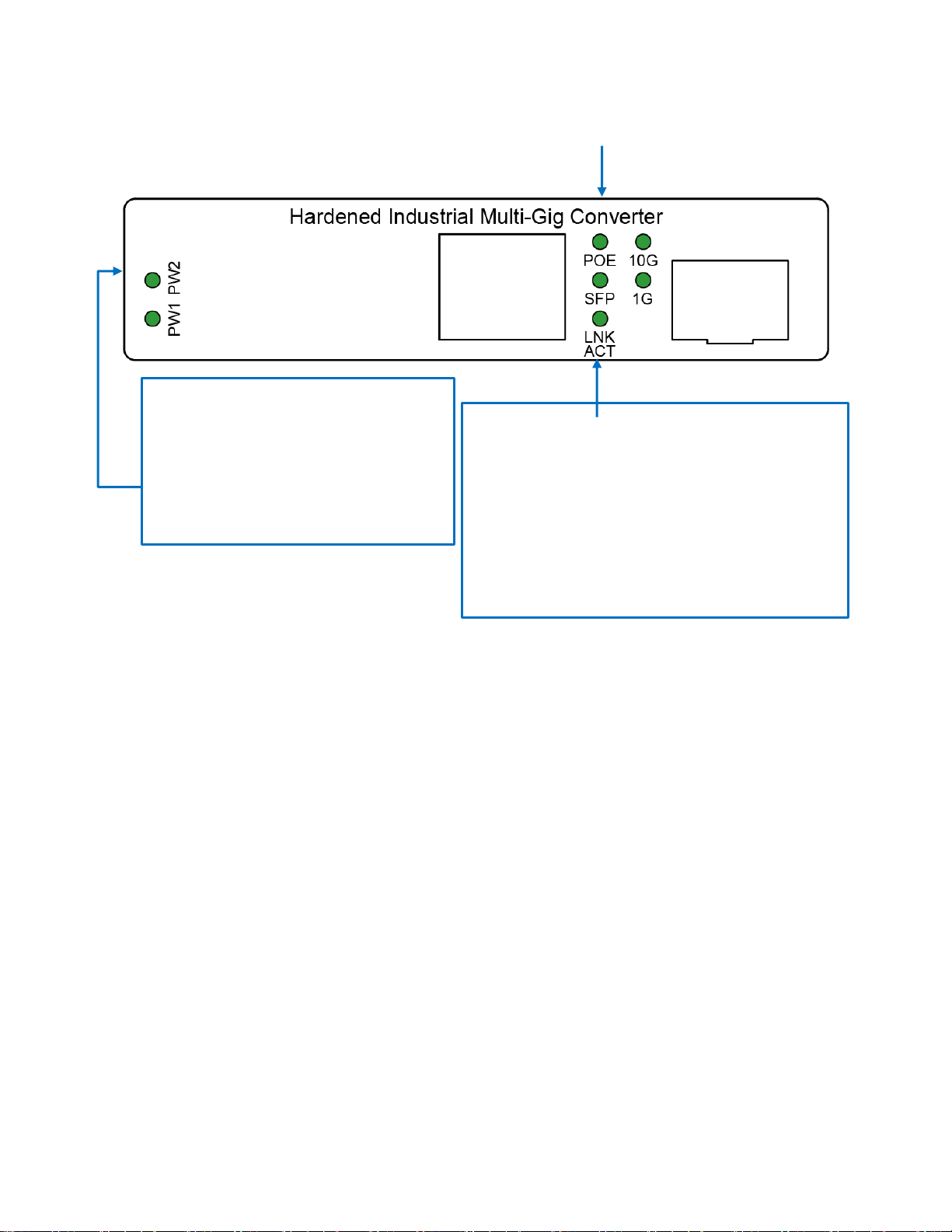
Patton’s FP102E/BT90 converts singlemode or multimode fiber to a copper Ethernet signal. With
the built-in high power PoE (Power over Ethernet) injector and a local power source, you can
easily and reliably extend both power (90 watts/high power PoE) and 1–10 gigabit Ethernet to
any PoE enabled end point including devices such as IP security cameras, IP speakers, digital
signage, VoIP phones, wireless access points, POS kiosks, BACs, PLCs, and more.
Because 10-gigabit Ethernet over Cat6a cables is limited to about 50 meters (164 feet), using
fiber as a backhaul allows for a massive increase in distances. SFP options for multimode can
reach up to 1.24 miles (2 km), and singlemode options can range as far as 37 miles (60 km). In
addition to the reach, you get fiber’s superior immunity to noise and harmful transients (surges).
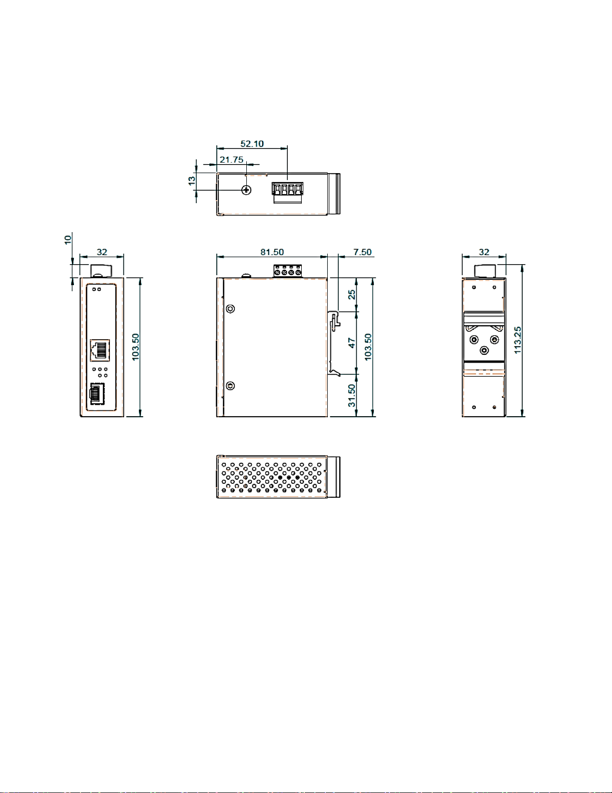
The FP102E/BT90 is housed in an IP30-rated DIN-rail or wall-mount enabled enclosure, and
has a wide operating temperature of -40 to 167°F (-40 to 75°C). Its rugged design and wide
temperature range makes it an ideal media converter for industrial or harsh environments. Its
bandwidth capabilities make it suitable for bandwidth hungry applications like telecom backhaul,
data centers, and AVoIP technologies that require 10-gigabit networks—like SDVoE and
HDBase-T.
.

3
Installation package
This unit can be din-rail or wall mounted. Din-rail brackets and wall mount brackets are included.
Power connection
This unit provides a 4-pin terminal block. It can be operated using 48-56VDC power source. Always make
sure your input voltage is within this supported voltage range.
To connect power: Follow the printed polarity for V+, V- and Ground. Connect positive wire to V+,
connect negative wire to V- and connect neutral wire to ground.
+V- is for power input connection, this unit has only one power input.
RLY is for relay connection.
Power connecting procedure:
STEP 1 – Take out 4 pin terminal block located in the
included mounting kit package.
STEP 2 – Connect power wire to +V- with correct
polarity and connect RLY for relay. Connect the
grounding wire to the ground screw.
STEP 3 – Plug into terminal block socket shown
above. Polarity needs to match V+ and V-.
WARNING -- Always SHUT OFF power source to
connect power wire.
WARNING -- Any exceeded input voltage will not make this unit function and may damage this
unit.
LED Indicator
PoE (Green)
ON – PD is detected on
designated port
OFF – no PD is detected
+V- RLY
+V1- +V2-

4
PW1(Green)
ON -- when P1+, P1- is connected
OFF – P1+, P1- is NOT connected
PW2(Green)
ON -- when P2+, P2- is connected
OFF – P2+, P2- is NOT connected
SFP (Green)
ON – FX port is detected
Flashing – FX data is transmitting/receiving
LNK/ACT (Green):
ON-TX port is detected
Flashing-TX data is transmitting/receiving
10G (Green): ON-TX port speed is 10G
1G (Green): ON-TX port speed is 1G

5
Specifications
IEEE Standard
IEEE 802.3ab 1000Base-T Gigabit Ethernet
IEEE 802.3an 10GBase-T Ethernet
IEEE 802.3af for PoE
IEEE 802.3at for PoE+/PoE++
IEEE 802.3bt
Compliant with 60W uPoE standard
Compliant with 95W Power over HDBaseT (PoH) standard
Media Supported
1000Base-T: Cat5 UTP/STP, max. 100 m (330 ft.)
10GBase-T: Cat6a UTP/STP, max. 50 m (164 ft.)
Work Mode
1000Base-T to 1000Base-X
10GBase-T to 10GBase-R
Network Connector
1 xRJ-45 1G/10GBase-T auto negotiation,
Auto MDI/MDI-X function, Full/Half duplex
1 x 1G/10GBase-X SFP
Protocol
CSMA/CD
LED
PW1 (Green): ON-Power 1 is detected
PW2 (Green): ON-Power 2 is detected
RJ-45 port:
PoE: ON – PSE is in active mode.
OFF – PSE is in idle mode.
LNK/ACT (Green): ON-TX port is detected
Flashing-TX data is transmitting/receiving
10G (Green): ON-TX port speed is 10G
1G (Green): ON-TX port speed is 1G
SFP port:
SFP (Green): ON-SFP port is detected
Flashing-data is transmitting/receiving
PoE Power
Maximum 70Watts with 56VDC input at environment 75°C
Maximum 90Watts with 56VDC input at environment 60°C
PoE Pin Assignment
Pin 1 (V-), 2 (V-), 3 (V+), 6 (V+)
Pin 4 (V+), 5 (V+), 7 (V-), 8 (V-)
Reverse Polarity Protection
Present
Overload Current Protection
Present
Power Supply
4 pin terminal block with 52-56VDC Power Input
Power Consumption
3 W@52 VDC full load
Removable Terminal Block
Provide 4 pin terminal block
Wire range: 0.34mm^2 to 2.5mm^2
Solid wire (AWG):12-24/14-22
Stranded wire(AWG): 12-24/14-22
Torque:5lb-In/0.5Nm/0.56Nm
Wire Strip length: 7-8mm
Operating Temperature
-40°C to 75°C
Operating Humidity
5% to 95% (Non-condensing)
Storage Temperature
-40°C to 85°C
MTBF (mean time between failure)
>500,000 hrs (Telcordia (Bellcore), GB) at 50°C

6
Housing
Rugged Metal, IP30 Protection
Case Dimension (LxWxD)mm
103.5 x 32 x 81.5 mm (LxWxD)
Installation
DIN-Rail and wall mount brackets included
Certifications
Safety
LVD (EN62368-1)
EMC
CE, FCC, EN 55032/24
EMI
CISPR 32, FCC Part 15B Class A
EMS
IEC 61000-4-2 ESD: Contact: 6KV; Air: 8KV
IEC 61000-4-4 EFT: Power: 2KV; Signal: 2KV
IEC 61000-4-5 Surge: Power: 2KV; Signal: 2KV
Vibration
EN 60068-2-6
Shock
EN 60068-2-27
Free Fall
EN 60068-2-32

7
Housing Dimension (mm)
NOTE:
Housing dimension is for purpose of showing product Length, Width, Height, din-rail, and terminal
block’s position and dimension. Please reference the LED Indicator Page for correct port order.
Table of contents
Other Patton Media Converter manuals