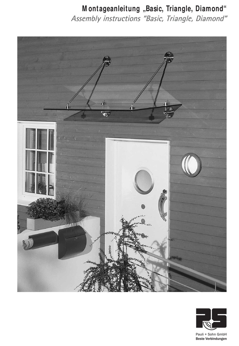
Pauli + Sohn VD 1510 User manual

VD 1510
Freitragendes Vordachsystem
Self-Supporting Canopy System
Montageanleitung
Assembly Instructions

2
VD 1510
Set-Inhalt | Set contents
Befestigungszubehör & benötigtes Werkzeug | Tools required and fastening material
1x Wand-Profil
1x Wall profile
S7991A2D10x40
(Senkkopfschraube)
(Countersunk)
Wasserwaage
spirit level
Innensechskantschlüssel
T-Griff oder ähnlicher
(SW6)
Allen wrench (SW6)
Stirnlochschlüssel
Adjustable face spanner
2x Klebepad
links/rechts
2x Adhesive pad
left/right
1501KL-300
(FIS V 300T)
(Hochleistungsmörtel)
(high performance mortar)
1x Auflageprofil
1x Overlay profile
1510-11VA
(Verbindungsstift)
(Connecting pin)
Bohrmaschine inkl.
entsprechendem Bohrer
Drill with drill bits
3-4x Glasfixierung
3-4x Glass support
fastener
1x oberes
Verglasungsprofil
1x Upper
glazing profile
Drehmomentschlüssel
torque wrench
1x Endkappe
links/rechts
1x End cap left/right
1x Kantenschutzprofil
1x Edge
protection profile
1979ST8-M10
(FIS E M10)
(Innengewindeanker)
(Internal threaded)
2x Glassicherung
2x Glass securing
fastener
mit und ohne VSG-Scheibe erhältlich
with or without LSG-panel available
Diese Montageanleitung beschreibt die Montage an einer Be-
tonwand. Weitere Montagemöglichkeiten wie an einem Stahl-
bauträger sind hier nicht weiter beschrieben. Montageschritte
ähnlich, jedoch mit anderem Befestigungsmaterial.
These assembly instructions describe the installation on a
concrete wall. More mounting options like on a steel suppor-
ters are not described here. The mounting steps are similar but
with different fastening materials.
900 bzw. 1100 mm
1398 / 1598 / 1998 / 2398
17,52
Montageanleitung gilt für:
Mounting instructions apply to:
SET1510E-17-A (1400mm)
SET1510E-17-B (1600mm)
SET1510E-17-C (2000mm)
SET1510E-17-D (2400mm)

3
Freitragendes Vordachsystem| Self-Supporting Canopy System
mit und ohne VSG-Scheibe erhältlich
with or without LSG-panel available
Schritt 1:
Richten Sie das Profil auf einer zur Befestigung geeigneten
Unterkonstruktion mittels Wasserwaage aus. Informieren Sie
sich bitte vorab über geeignetes Befestigungsmaterial. Nutzen
Sie die Bohrungen des Wandprofils zur Bestimmung der Be-
festigungsbohrungen.
Hier ist es sinnvoll mit zwei Personen zu arbeiten.
Step 1:
Align the profile on a suitable substructure using a spirit level.
Inform yourself in advance of suitable fastening materials. Use
the holes in the wall profile to determine the mounting holes.
It is advisable to work with two people.
FG
FG
<
>
FG
FG
<
>
+

4
VD 1510
Schritt 3:
Nachdem Sie die Bohrungen von sämtlichen Bohrrückstän-
den etc. gereinigt haben, füllen Sie den Injektionsmörtel
FIS V 300T mit einer geeigneten Presse in das Bohrloch.
Step 3:
After cleaning of all the holes, fill the holes with injection mortar
FIS V 300T with a suitable cartridge gun. Please observe the
manufactures instructions.
Schritt 2:
Bohren Sie nun die angezeichneten Bohrlöcher. Bitte beachten
Sie vor dem Bohren der Löcher die Art des Befestigungsuntergrun-
des. Der Bohrlochdurchmesser richtet sich nach Art des Befesti-
gungsuntergrundes. Nachgewiesene Befestigungsmöglichkeiten
entnehmen sie bitte unserer Statik. Eine mögliche Befestigungs-
art ist FIS E 15x85 M10 für Beton. Die genauen Angaben
über Mindestbohrtiefe, Bohrdurchmesser etc. sind den Daten-
blättern des Herstellers zu entnehmen.
Säubern Sie die Bohrlöcher nach dem Bohrvorgang.
Step 2:
Now drill the marked holes. Before drilling the holes, make
sure to know what type of mounting substrate is present. The
drill hole diameter depends on the type of mounting substrate.
According to manufacturer there are different mounting options
for each substrate. For proven types of fastening please refer
to our static calculation. One possible fastening type is FIS E
15x85 M10. Please refer to the manufacturer‘s data sheets for
the detailed information on the minimum drilling depth, drilling
diameter, etc. Clean the holes after drilling.
Bohrabstand gemäß angezeichneten Profilbefestigungsbohrungen.
Drill spacing according to the profile mounting holes
ACHTUNG - Herstellerangaben beachten!
ATTENTION – Follow manufacturer‘s instructions

5
Freitragendes Vordachsystem| Self-Supporting Canopy System
Schritt 4:
Nachdem Sie den Injektionsmörtel FIS V 300T wie in Schritt 3
beschrieben in die Bohrlöcher gefüllt haben, können die Innen-
gewindeanker FIS E 15x85 M10 in die vorbereiteteten Bohrlö-
cher gesteckt werden (leichte Drehbewegungen erleichtern das
Einsetzen).
Für das Setzen der Innengewindeanker ist kein besonderes
Werkzeug erforderlich. Bei richtiger Anwendung verklebt der
benutzte Injektionsmörtel das Befestigungselement vollflächig
mit der Bohrlochwand.
Step 4:
After the injection mortar FIS V 300T is filled as described in
step 3 in the drilled holes, the internal thread anchor FIS E
15x85 M10 can be inserted into the prepared holes (slight
rotational movements eases insertion). No special tools are re-
quired for this. When used correctly, the injection mortar bonds
the entire surface of the fastening element.
Innengewindeanker FIS E 15x85 M10
threaded plug FIS E 15x85 M10

6
VD 1510
Schritt 5:
Nachdem die Innengewindeanker zusammen mit dem Injek-
tionsmörtel FIS V 300T ausgehärtet sind, kann das Vordach-
profil mit den vorgesehenen Innensechskantschrauben DIN
7991 M10x40 am Bauträger befestigt werden. Ziehen Sie die
Schrauben mit einem Innensechskantschlüssel SW6 nur Hand-
fest an. Ziehen Sie zum Abschluß alle Schrauben mit einem
geeigneten Dremomentschlüssel nach.
Anzugsmoment 30N*m.
Step 5:
After the injection mortar FIS V 300T has cured in the internal
threaded anchor, the canopy profile can be mounted with the
screws DIN 7991 M10x40. Tighten the screws with an Allen
key SW6 only hand tight. Tighten all screws with the given
torque to 30N*m
max. Anzugsmoment 30 N*m
max.torque 30 N*m
FG
FG
<
>
FG
FG
<
>
+

7
Freitragendes Vordachsystem| Self-Supporting Canopy System
Schritt 6:
Bevor das Glas in das Vordachprofil montiert werden kann,
muss das hintere Kantenschutzprofil auf das Glas gesteckt wer-
den. Siehe hierzu die Detailansicht. Das hintere Kantenschutz-
profil bitte nach der Montage am Glas mit Gleitmittel CARAM-
BA 6136001 einsprühen. So ist sichergestellt, das es beim
nächsten Montageschritt keine Komplikationen gibt.
Step 6:
Before the glass can be mounted into the canopy profile, the
rear edge protection must be clipped onto the glass. See the
detailed illustration. Please spray the rear edge trim profile after
mounting the glass with lubricant CARAMBA 6136001. This
ensures that there are no complications during the next assem-
bly step.
Achten Sie beim Einbau darauf, das diese Kerbe sich auf der Vordachoberseite befindet.
When installing, be sure that this notch is on the top.
HINWEIS!
Bei der Vordach-Glasproduktion ist darauf zu achten, dass
kein überflüssiges SentryGlas® in die Bohrung (hell grauer
Bereich) fließt.
Kann dies nicht ausgeschlossen werden, so ist das Sentry-
Glas® im Bereich der Bohrung auszusparen oder nachträg-
lich zu entfernen. Bitte vor Montage durch Sichtkontrolle
prüfen.
Important note:
During the glass production attention should be paid that
no surplus SentryGlas® flows into the drillings (light grey
marked area).
If this cannot be excluded, the SentryGlas® in the areas of
the drillings has to be either left out or removed afterwards.
Please verify the faultless condition of the drillings through
visual inspection before installation.
Vordachoberseite
Canopy upper side
hinteres Kantenschutzprofil
Rear edge trim
Vordachunterseite
Canopy lower side

8
VD 1510
Schritt 7:
Vor der Montage der Glasscheibe am Vordachprofil müssen
alle vormontierten Fixierelemente aus dem Profil geschraubt
werden. Nutzen Sie zum Herausschrauben einen geeigneten
Stirnlochschlüssel.
Step 7:
Before mounting the glass panel into the canopy profile, all
preassembled fasteners are to be unscrewed from the profile.
Use a suitable face spanner.
alle Fixierelemente mit Hilfe eines
geeigneten Stirnlochschlüssel aus dem
Profil herausschrauben.
Remove all fasteners by means of a
suitable face spanner from the profile.

9
Freitragendes Vordachsystem| Self-Supporting Canopy System
Schritt 8:
Die Glasscheibe mit den Bohrungen nach unten in das Profil
drücken und bis zum Anschlag einführen. Bitte dabei darauf
achten, dass die Scheibe in der Mitte gestützt wird und sich
nicht durchbiegt (evtl. dritte Person notwendig). Ohne mittlere
Abstützung kann die Glasscheibe sonst beim Eindrücken blo-
ckieren. Falls keine dritte Person zur Verfügung steht, kann hier
z. B. mit einer neigungsverstellbaren Hebevorrichtung mit Glas-
saugern gearbeitet werden.
Step 8:
Press the glass plate with the holes facing downward into the
profile and insert it until it stops. Be careful that the glass panel
is supported in the middle so it does not bend (a third person
might be necessary). Without supporting the middle of the glass
panel, it may block during inserting. If a third person is not
available, a tilt-adjustable lift with suction cups can be useful.
FG
FG
<
>
FG
FG
<
>
FG
FG
<
>
+ +
Vor der Montage der Glasscheibe das innen-
liegende EPDM Profil ebenfalls mit Gleitmittel
z.B. CARAMBA 6136001 einsprühen.
Before mounting the glass panel, lubricate
the internal EPDM profile with for example
CARAMBA 6136001 Spray.

10
VD 1510
Schritt 9:
Nachdem die Glasscheibe in das Vordachprofil gedrückt wur-
de, kann diese durch leichtes Anheben vom Verglasungsgummi
nun seitlich ausgerichtet werden. Wenn die Ausrichtung der
Glasscheibe erfolgt ist, kann durch Eindrehen der jeweils äu-
ßeren Fixierelemente (mit Glassicherungspin) die Scheibe ge-
gen Herausrutschen gesichert werden. Benutzen Sie bitte hierzu
einen passenden Stirnlochschlüssel. Sind die beiden äußeren
Fixierelemente eingedreht, können auch die anderen Fixierele-
mente gegen das Glas angeschraubt werden.
Step 9:
After the glass panel has been pressed into the canopy profi-
le, the panel can now be aligned by slightly lifting the upper
glazing gasket. Once the alignment of the glass panel is done,
screw in the securing fasteners with safety stud. The glass panel
is now secured from slipping or being pulled out. Please use a
suitable face spanner for this.
The two support fasteners can now be screwed into the profile.
äußere Fixierelemente ein-
gedreht, Glas gesichert.
Securing fasteners are in-
serted, glass is secured.
Stirnlochschlüssel
Face spanner

11
Freitragendes Vordachsystem| Self-Supporting Canopy System
Schritt 10:
Nachdem die Glasscheibe im Vordachprofil gesichert ist, kann
die obere Verglasungsdichtung eingesetzt werden. Hier emp-
fiehlt es sich etwas Gleitmittel CARAMBA 6136001 zu verwen-
den. Dies erleichtert den Montageschritt. Nun können die linke
und rechte Abdeckkappe montiert werden.
Lösen Sie hierzu die Folie der Klebefläche von der Abdeck-
kappe. Kleben Sie die Abdeckkappe an die linke bzw. rech-
te Profilseite und verschrauben Sie diese mit der beiliegenden
Senkkopfschraube.
Step 10:
After the glass panel is secured in the canopy profile, the upper
glazing gasket can be inserted. It is advisable to use lube CA-
RAMBA 6136001 to make this assembly step easier. Now the
left and right end cover caps can be mounted.
Remove the protection foil from the adhesive and adhere the
end caps to the profile. Now secure them to the profile with the
provided countersink screws.
obere Verglasungsdichtung
Upper glazing gasket
Einbaulage oberes
Verglasungsprofil
Inserted upper
glazing gasket Hinweis: Das Aluprofil muss mindestens so lang sein wie die verwendete Glasbreite, so
das die Abdeckkappen beidseitig montiert werden können.
Note: The aluminum profile must be at least as long as the used glass panel so that the
end cover caps can be mounted on both sides.
obere Verglasungsdichtung einsetzen
insert the upper glazing gasket
Abdeckkappe links im
montierten Zustand
End cover cap in finished
assembly

Version B. 01-2017
Alle Bilder, technische Zeichnungen und deren Beschreibungen sind
urheberrechtlich geschütztes Eigentum der Pauli + Sohn GmbH.
Technische Maßangaben innerhalb des Kataloges sind unver-
bindlich. Konstruktionsänderungen sind vorbehalten. Bitte beachten
Sie unsere Schutzrechte. Für Druckfehler und Irrtümer, die bei der
Herstellung unterlaufen sind, ist jede Haftung ausgeschlossen.
www.pauli.de Technischer Stand: April 2017
Edition B. 01-2017
All images, technical drawings and descriptions are copyrighted
property of the Pauli + Sohn GmbH. Technical measurements within
the catalog are not binding and are subject to change. Any liability
for printing errors which have occured during the preparating of this
brochure is excluded.
www.pauli.de Technical status: April 2017
This manual suits for next models
4
Other Pauli + Sohn Tent manuals
