Paulin Model 9 User manual

Owners Guide
Read all information and instructions, including Gaslight Warning Tag attached to light,
before installation or use. Retain this guide for future reference.
Indoor Gaslights
Information and Instructions
Model 9 for homes, cottages, and cabins (pre-formed mantle).
Model 9T must be used for recreational vehicles (tie-on mantle)
The design of Model 9 and 9T is C.S.A. certified. Installation must
conform with local codes or, in the absence of local codes, with the
National Fuel Gas Code,ANSI Z223.1 (latest edition), and/or with
CAN1-B149.2 (latest edition) installation code for propane and butane
burning appliances and equipment, and local codes.
IMPORTANT INFORMATION FOR USING PAULIN INDOOR GASLIGHTS
Use Gaslights only for purposes of illumination. Installation and repair of equipment that operates on
propane or butane gas is a job for experts. Do not attempt to install or repair your gaslight unless you
have been thoroughly trained and are experienced in such matters. If your gaslight appears to be mal-
functioning, turn it to the “OFF” position and immediately contact your local dealer or the Paulin factory.
After installation and before use, have qualified gas personnel
approve your installation and check for gas leaks using a leak
detector. Tubing, fittings, gaslight valve, and any other gas
transporting component should be checked. Subjecting
valve assembly to testing pressures in excess of 6 PSI
can damage sealing grease which can cause leaks and
voids warranty.
Use your gaslight in vented rooms only.
Carbon monoxide is produced by the incomplete
combustion of fuel.
Attention Installer:
C.S.A. requires that you leave these instructions
with the appliance for the consumer.
Caution
If you smell gas:
1. Shut off gas to appliance.
2. Open windows
3. Don’t touch electrical switches
4. Extinguish any open flame.
5. Immediately call your gas supplier.
DO NOT STORE OR USE GASOLINE
OR OTHER FLAMMABLE VAPORS
AND LIQUIDS IN THE VICINITY OF
THIS OR ANY OTHERAPPLIANCE.

RECOMMENDEDMAINTENANCE:
The following matters should be dealt with as frequently as necessary in your particular case.
If your gaslight has been out of use for a period of time, examine it before lighting it.
Keep area clear and free from combustible materials, including gasoline and other flam-
mable vapors and liquids. Flow of combustion air and ventilation air must not be obstructed.
Use propane gas only for Model 9 and 9T. Propane gas must be to this rating: 2500 to 2530
B.T.U per cubic foot. Paulin propane gas nozzles are drilled to this rating only. They will not
function properly if used otherwise. See “Gaslight Warning Tag.”
Natural Gas. Paulin gaslights can be used with natural gas, but only as follows: Natural gas
must be to this rating: 1000 to 1100 B.T.U. per cubic foot (4 inches of water column / 2.18 oz.
of mercury). Do not use propane or butane gas nozzles. Use Paulin Nozzle, #L9-51A.
Propane or Butane gas supply tank and regulator. Gas supply tank must not be overfilled.
Regulator must be adjusted to operate at a pressure of 11 inches of water column (27.9 cm)
(6 oz. of mercury). This same gas pressure must be maintained at the nozzle of the gaslight.
Higher or lower pressures will cause the gaslight to malfunction.
Copper gas tubing. Copper gas tubing must be internally tinned to meet National Gas Code
Standards unless otherwise directed by local codes.
Nozzle. All gaslights are equipped with standard propane nozzles. To use gaslights at eleva-
tions of 4500 feet or more above sea level, order HighAltitude Nozzle, #L9-52A for propane gas,
or #L9-61A for butane gas.
Note: Never touch drilled hole in nozzle as it is extremely delicate. Use compressed air to
clean the nozzle. Pins, wire, even oil from hands may disturb proper gas flow. Replace nozzle if
in question.
Both Series 9 and 9T are
ready to use with
PROPANE ONLY, at
altitudes under 4,500 ft.
The following gas nozzles
are available for these
other applications:
Valve Assembly. The valve assembly must be straight on the wall bracket. Bracket can be-
come coked or bent when tightening copper tubing, flare nut, etc., causing nozzle to be aimed
crooked. Gas flow through the nozzle must be aimed straight down the center of the Bunsen.
When gaslight is operating properly, gas consumption is 2000 B.T.U. per hour. One “pound” of
propane or butane gas produces approximately 12 hours of light.
Permanent screws that attach valve assembly to wallplate should never be loosened or re-
moved. Removing valve assembly from wallplate will void warranty.
FUEL TYPE GAS NOZZLE
BUTANE L9-60A
PROPANE(HIGHALTITUDE) L9-52A
BUTANE (HIGHALTITUDE) L9-61A
RECOMMENDED MAINTENANCE CONTINUED
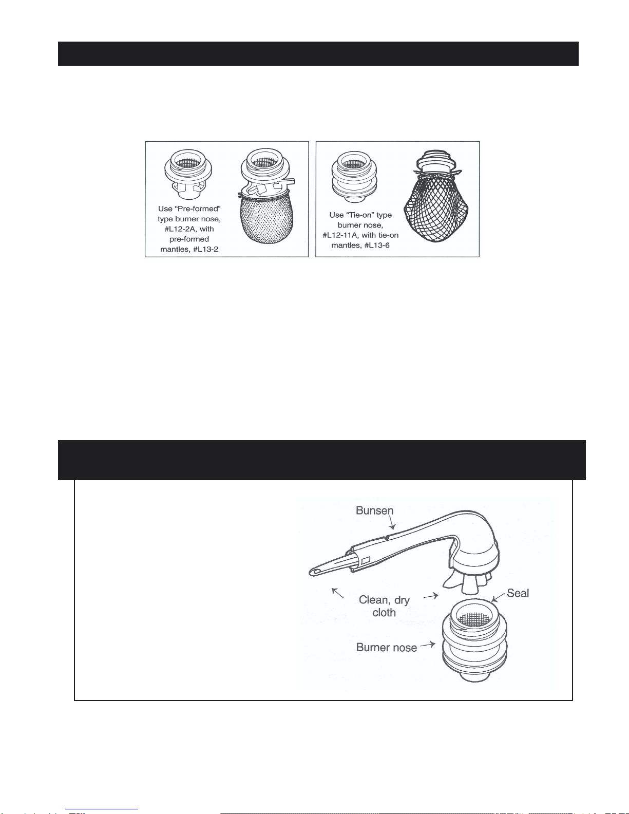
Mantles. Use Paulin mantles which are designed for use with propane and butane gas only. Never use broken
mantles. Inspect for carbon deposits each time gaslight is used. Clean or replace defective mantles immediately.
Use proper ceramic burner nose and mantle combination. (Example: “Tie-On” type burner nose, #L12-11A, with
tie-on mantles, #L13-6. Or “Pre-formed” type burner nose, #L12-2A, with pre-formed mantles, #L13-2.) Also see
“Mantle Installation and Lighting Instructions.”
Burner Nose Screen. Screen must be in threaded end of burner nose. Gaslight will not function properly if screen is
missing.
Seal. Seal is placed on threaded end of burner nose. Seal and burner nose should be screwed securely into bunsen.
The seal must be replaced anytime the burner nose is removed after the lamp has been used.
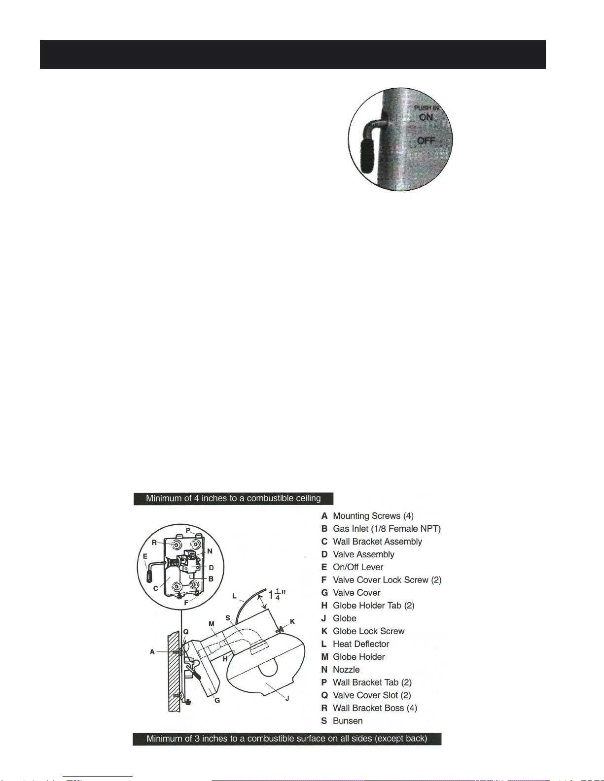
Bunsen. Flow of combustion air and ventilation air must not be obstructed. To ensure proper air flow and gas mixture,
the inside of the bunsen must be clean and free of any material that may potentially accumulate, such as spider webs,
insects, etc. Make a periodic visual check of the Bunsen. The Bunsen can be cleaned by drawing a clean, dry cloth
through it. It can also be cleaned by blowing it out with compressed air. Never attach a mantle directly to the Bunsen.
BUNSEN CLEANING INSTRUCTIONS
1. Remove burner nose.
2. Pull a clean, dry cloth
through Bunsen to clean
out foreign material.
3. Replace seal.
Reassemble burner
nose and tighten securely.
Note: Always replace seal if
lamp has been previously lit.
or L13-8 Quick-Clip
GASLIGHT LOCATION, MOUNTING & ASSEMBLY
Read all instructions and Gaslight Warning
Tag (attached to light) before installing light.
Make sure that the gas supply is turned OFF
at the supply tank and that the gaslight valve
handle is in the “OFF” position.
Plumbing Supplies:
The following plumbing supplies are needed for installation. They are available from your
local gas dealer.
Copper Tubing:
Internally tinned copper tubing, 3/8-inch outside diameter, is recommended. Copper tubing
must be internally tinned to meet National Fuel Gas Code unless otherwise directed by local
codes.
Fittings: If 3/8-inch copper tubing is used, a 3/8-inch Flare Male Connector x 1/8 NPT
Straight Fitting is required, Paulin #L22-12A (included).
If Gaslight is to be connected from behind (through wall), a 1/8 NPT Street Elbow (Male-
Female), Paulin #L22-23A (included) must be used in addition to the Straight Fitting.
Permanent screws that attach valve assembly to wallplate
SHOULD NEVER BE LOOSENED OR REMOVED.
Removing valve assembly from wallplate WILL VOID WARRANTY.

GASLIGHT LOCATION, MOUNTING & ASSEMBLY continued
LOCATION OF INDOOR GASLIGHT
Always mount gaslight on an open wall or from a ceiling with pendant kit. Never
mount gaslight in a boxed-in or recessed area.
Wall BracketAssembly (C) must be mounted so that Heat Deflector (L) is a minimum of four
inches from a combustible surface, and outside of Globe (J) is a minimum of three inches
from a combustible surface to either side or in front. Mounting gaslights too close to a door
may subject delicate mantles to vibrations and could damage the mantle.
Assembly:
First, remove all packaging materials from gaslight.
1. Remove Wall Bracket Assembly (C) and visually identify ValveAssembly (D) and Nozzle (N).
From center of Nozzle, measure a minimum of seven inches below an overhead combustible
surface, and a minimum of ten inches from a combustible surface at the front. These dimensions
will provide the minimum clearance to combustible surfaces for the Heat Deflector and Globe.
DO NOT TOUCH, DISTURB OR DAMAGE HOLE IN NOZZLE, even oil from hands can interfere
with proper gas flow.
If gas supply is to be connected through bottom of Valve Cover (G) remove Knockout tab (twist
out using pliers) in valve cover before proceeding.
2. Connect internally tinned copper tubing to Gas Inlet (B) using proper fitting (See “Fittings”
page 4). It is easier to connect the tubing before fastening Wall Bracket assembly to wall (also
Wall BracketAssembly is less likely to be bent). Valve Assembly (D) must be straight on the Wall
Bracket. Nozzle (N) must aim into the center of the Bunsen (S) for proper air and gas mixture.
3. Fasten Wall BracketAssembly to wall using four mounting screws (A) supplied. CAUTION: DO
NOT OVERTIGHTEN SCREWS. The four Bosses (R) on the Wall BracketAssembly must not be
imbedded in the wall because air must circulate behind the Wall Bracket Assembly to prevent
scorching.
4. Attach Valve Cover Assembly (G) to Wall BracketAssembly by engaging Slots (Q) with Wall
BracketAssembly Tabs (P).
5. Carefully swing down the Valve CoverAssembly so that the slots in the bottom of the valve
cover engage Lock Screws (F). Tighten Lock Screws.
6. Check the following dimensions:
Minimum of 4 inch clearance from top of Heat Deflector (L) to ceiling.
Minimum of 3 inch clearance from outer edge to both sides and front.
Ensure 1-1/4 inch dimension between Heat Deflector and Globe Holder (M)
7. Loosen Globe Lock Screw (K), and remove Globe. Be sure that all packaging material has
been removed. Attach mantle.
8. Attach Globe after installing mantle but before burn-off (See “Mantle Installation and Lighting
Instructions”) by engaging Tabs (H) and inserting Globe so that Globe Lock Screw can be tight-
ened into the neck of the Globe. Do not overtighten.
Replacement parts and accessories are available from your local gas dealer or from
Paulin Products, Inc.

MANTLE INSTALLATION & LIGHTING INSTRUCTIONS
Do not use defective mantles (holes, etc.) Replace defective mantles
immediately.
After installation and before use have qualified gas personnel approve your
installation and check for gas leaks using a leak detector. Tubing, fittings, gas-
light valve, and any other gas transporting component should be checked. After
gaslight has been properly installed and thoroughly checked for leaks by qualified
gas personnel only:
1. Remove globe.
2. a. Pre-form mantle: Grasp ceramic ring -
do not touch mantle itself. Hook legs into
reverse “L” of the burner nose.
b. Tie-on mantle: Loop the tie-on strings at
the throat of the mantle. Work fingertips into
mantle throat and enlarge the opening so that
it will fit over the ceramic burner nose and seat
in lower groove of burner nose. Do not tie the
mantle to the Bunsen. Distribute puckers in
the mantle evenly around the burner nose.
Pull the ends of the string snugly so that
mantle and string are seated securely in
the burner nose groove. Tie a double knot
and clip off excess string.
3. Replace globe.
4. Mantle burn-off: WITH GASLIGHT VALVE HANDLE IN THE “OFF” POSITION, and in a
well ventilated room, hold a lighted match close to, but not touching, bottom of mantle. Re-
move match when mantle begins to smolder. Allow fabric to burn completely.
5. Lighting of gaslight: Light gaslight only after mantle burn-off (Step 4) has been completely
accomplished. Caution: Do not turn gaslight to “On” position until after lighting match. Do
not touch mantle with the match.
6. Turning gaslight off: To turn off, simple move gaslight valve handle to the “OFF” position.

LIMITED WARRANTY
Paulin Products, Inc., as Manufacturer, warrants its indoor gaslights to the ORIGINAL
PURCHASER only and only to the extend and conditions below:
1. For a period of the earlier of thirty (30) days after purchase or one (1) year after date of
manufacture (date is metal stamped on Wall Plate), at Manufacturer’s option, will repair or
replace any parts EXCEPT glass parts, gaskets, or mantles found under normal use to be
defective in factory materials or workmanship.
2. This warranty will apply and the repair or replacement will be made without charge, only if:
a. The unit is used in an unaltered form and assembly and only indoors and only for
appropriate illumination purposes.
b. The unit is used with propane gas (model 9 or 9T) or butane gas (model 9B or 9BT)
only in a well ventilated area.
c. The unit shall not have been installed or serviced by anyone other than by a
qualified gas service personnel.
d. The unit shall have been installed, operated and maintained in accordance with
the instructions and purchaser shall have read and heeded the warnings
regarding use.
e. The unit shall be shipped (less globe) to Paulin Products, Inc. at the address below,
freight prepaid, accompanied by a letter stating service or repairs desired.
Be sure to give full information, including date and place of purchase, full name
and address.
3. Manufacturer reserves the right to, and at its option may, refund the purchase price in full
satisfaction of any warranty obligations hereunder.
4. Manufacturer shall not be liable for incidental or consequential damages and in all events
its liability hereunder shall not exceed the purchase price of the unit.
5. MANUFACTURER DISCLAIMS ANY OTHER WARRANTY AND THIS WARRANTY IS
EXPRESSLY GIVEN IN LIEU OF ALL OTHER WARRANTIES EXPRESS OR IMPLIEDAND
INCLUDING BUT NOT LIMITED TO THAT OF MERCHANTABILITY, ANY WARRANTY
WHICH MAY BE IMPLIED BY LAW SHALL BE LIMITED IN TIME TO THE DURATION OF
THIS WRITTEN WARRANTY.
6. Manufacturer neither authorizes nor assumes responsibility for any other affirmation of fact,
description or representation with respect to its products. Manufacturer neither assumes nor
authorizes any person to assume any obligation or liability with regard to its products except as
expressly set forth herein.
Note: Some states do not allow limitations on how long an implied warranty lasts or the
exclusion or limitation of incidental or consequential damages, so the above limitations or
exclusions may not apply to you. This warranty gives you specific legal rights which may
vary from state to state.
PAULIN PRODUCTS, Inc.
Sales Office: 36 South Franklin Street • Chagrin Falls, OH 44022 • 440-247-0828 • FAX: 440-247-7443
www.paulinproducts.com
This manual suits for next models
2
Table of contents
Popular Home Lighting manuals by other brands


Safavieh Lighting
Safavieh Lighting BROCKTON TBL4085A manual

LLOYTRON
LLOYTRON Zenith L2202 operating instructions

Safavieh Lighting
Safavieh Lighting Bixby TBL4265A quick start guide

WE-EF
WE-EF DOC110 LED Installation and maintenance instructions

Philips
Philips myLiving 37776/17/16 user manual

OttLite
OttLite T96G5R quick start guide

John Lewis
John Lewis BALDWIN user guide

Philips
Philips Ledino 422213126 brochure

Exo Terra
Exo Terra LIGHT DOME PT2055 operating instructions

Vistosi
Vistosi DAMASCO AP P KIT Assembly instruction

Lightolier
Lightolier Lytespan Track Lighting System DRL16 Specification sheet

Safavieh Lighting
Safavieh Lighting ARCHIE IRON FLL4090A manual