PAW FlowCon FA User manual

In North America for technical Assistance
Contact Solarnetix Inc. 416/699-6746
www.solarnetix.com / info@solarnetix.com
.
Page 1 of 12
User Guide
For FlowCon FA Solar Stations

Page 2 of 12
Specifications:
Solar station “FlowCon“
Height:
( incl. insulation )
550 mm/ 21 5/8 in
Width:
( incl. insulation )
280 mm/ 11 in
Spacing supply/ return:
125 mm/ 4.9 in
Pressure max.:
8 bar/ 116 PSI
Temperature max.:
120°C/248°F
Short-term 160 °C/320°F
Tube connections:
¾“ female
( on the solar station )
Safety Devices:
Pressure Relieve valve:
6 bar/87
PSI
Pressure gauge:
0 –6 bar
0 –87 PSI
Connection for expansion tank:
¾“ NPT female
Shut-off - / Indication Devices:
Ball valve:
Full port ¾“
Dial thermometer:
0 –160 °C/ 32-320°F
Flow-check Valves:
Pressure Drop:
2 x 200 mm/7.9” W.C.= 400 mm/15.8” W.C.
type:
PPS
Temperature max.:
180 °C/356°F
Flow Meter:
Range of indication/adjustment:
1 –13 l/min
connections:
¾” BSP female, 1” nut flat sealing
Additional connections
1 x ½“ BSP female
Gasket Material
O –Ring: VITON / EPDM
180 °C/356°F
gaskets: AFM 34
200 °C/392°F
Insulation:
Material:
EPP, = 0,041 W/(mK)

Page 3 of 12
screws S6 x 60
Installation Instructions
Wall Mounting:
1. Determine the location were the solar station will be installed.
2. Take the complete solar station out of the packaging.
3. Take off the thermometer with handle by tearing strongly forward.
4. Take off the front insulation shell of the solar station.
Leave the solar station assembled with the back insulation shell
5. Mark the drill holes (distance 70 mm/ 2 ¾”) and drill them with an 8 mm/ 5/16” bit.
6. Insert the attached plugs (S 8) into the holes.
7. Attach the complete solar station to the wall by using the enclosed screws.
8. Connect the piping between the solar station, storage and collectors.
All connections were tightened in the factory so that in general, it is not
necessary to tighten them again. Nevertheless it is important to carry
out a pressure test during the system setup.

Page 4 of 12
Commissioning
Filling, Flushing and Commissioning of the Solar Station
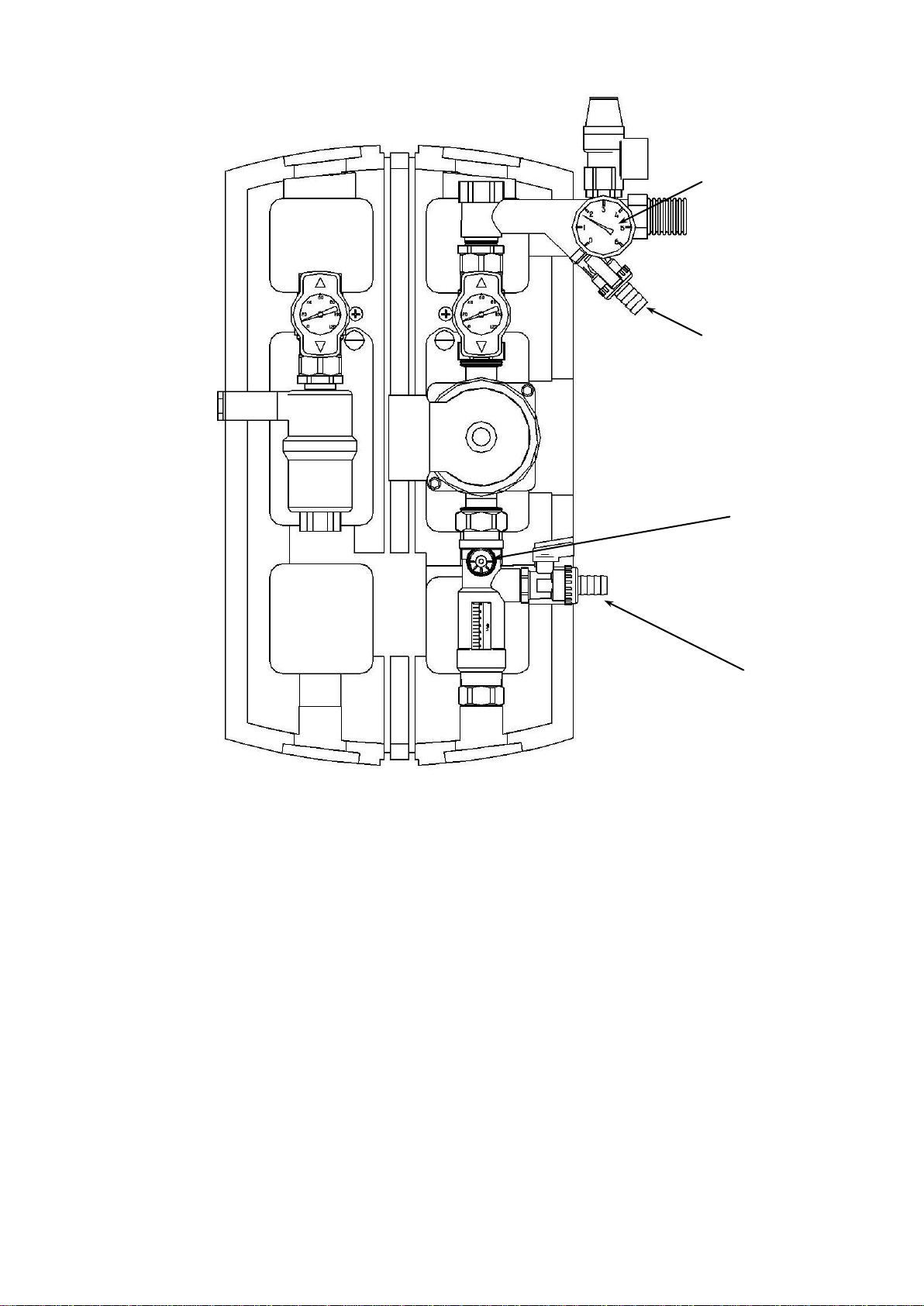
1. Connect the pressure hose to the fill valve (2) below the pressure gauge (1) and open the valve.
2. Connect the flush hose to the flush valve (4) on the flow meter (on the ball valve below the
pump) and open the valve.
3. The slot of the screw at the flow meter (3) has to be in a horizontal position. This way, the
integrated ball valve is closed (see user’s guide for the flow meter). Open both check valves
(over the pump and inside the supply valve); in order to do this, bring the ball valve into a 45°
position (half open, half closed) using 14 mm or 9/16 wrench.
4. Fill up solar fluid into the clean container and charge the solar loop using external service pump.
5. Flush the solar circuit for at least 15 min. In order to remove all of the air from the system, it is
necessary time to time to open the balancing screw on the flow meter.
6. Never flush or make a hydrostatic pressure test of the whole solar installation only
with water. It is impossible to completely empty the installation; there is a danger of
icing damages!
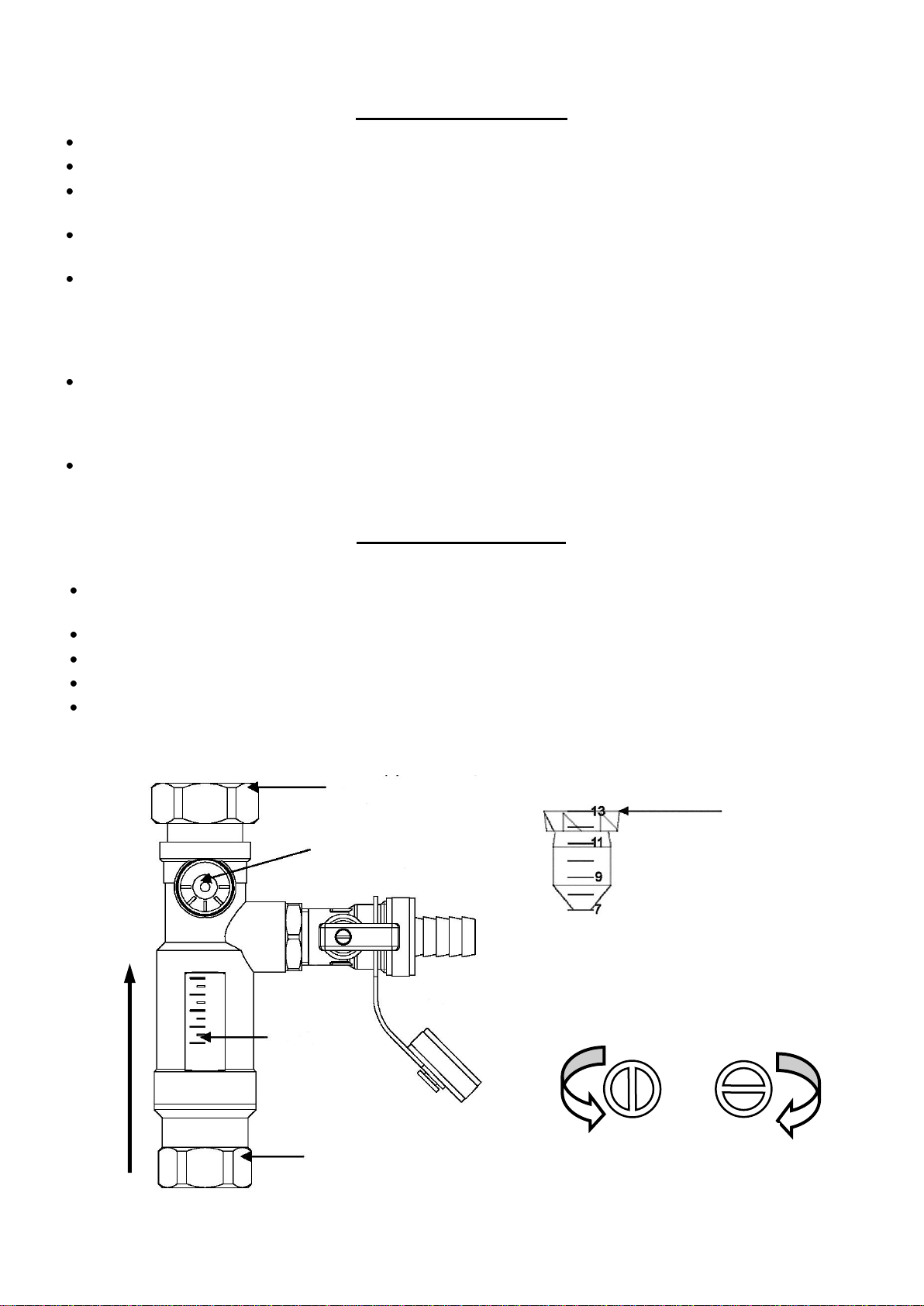
7. Close the flush valve (4) while the pump is still working and increase the pressure of the system
to approx. 5 bar/ 72 PSI. You can read the pressure from the pressure gauge (1).
8. Close the fill valve (2) and switch off the service pump. Open completely the balancing valve at
the flow meter (slot vertical).
9. Bleed the installation from above the collectors until the heat transfer fluid comes out free from
bubbles. If necessary, increase the pressure to approx. 5 bar/72 PSI and check for the leaks on
all the joints. If there is a considerable pressure drop on the pressure gauge (1), you can assume
that there is a leak in the system.
10. Adjust the operating pressure in accordance with the installation requirements (approx. 1,8
bar/28 PSI for a static height between the collectors and the pressure gauge of 5 m/16 ft; and
to 2,3 bar/33 PSI for a static height 10 m/32 ft).
11. Set the circulation pump on the highest speed level (see user’s guide of the pump and the
controller) and keep it circulating for at least 15 min. Adjust the circulation pump to the desired
RPM level.
12. Adjust the flow rate on the flow meter in accordance to collector manufacturer’s instructions.
13. Disconnect the hoses of the fill pump and cap the flush and fill valves with supplied cups.
14. Double check the possible leaks of the installation. Open both shut-off ball valves completely.
15. Fix the front shell of the solar station. Insert the red handle with thermometer in the supply line
(on the left side) and the blue handle with thermometer in the return line (on the right side).

Page 5 of 12
Draining the Solar Loop
1. Open the flow check valves located inside the ball valves (see the following instructions).
2. Open the venting valves at the highest point (above the collectors).
3. Open the valve at the lowest point of the installation, if possible near the connection of the
storage (not included in the delivery) or at the flush valve (outlet valve) below the pump.
1
2
3
4

Page 6 of 12
Flow Check Valves
The flow check valves are integrated inside the thermometer ball valves and have an opening pressure
of 200 mm / 7 7/8 “ W.C. each.
In order to fill, bleed or drain the system, the flow check valves need to be open. For this, you
have to bring the handles of the ball valves into a 45° position (see illustration). The balls of the
ball valves push open the flow check devices.
For proper operation of the system the ball valves need to be completely open.
NOTE:
The group air vents has to be installed with sufficient distance to the collectors (due to the
possibility of high temperatures directly behind the collectors)! For an assembly in the attic, it has to
be ensured that the air vents can not overheat (e. g. by means of a “steam scoop”)!
The expansion tank has to be checked regularly in accordance with local Plumbing Code.
Solar installations have to be grounded for reasons of lightning protection.
Only skilled and trained electrical personnel are authorized to carry out wiring operations. All field
wiring made during installation must comply with:
o–National Electrical Code NFPA 70 and any other national, state, provincial or local codes or
requirements.
o–In Canada, CSA C22.1 Canadian Electrical Code Part 1, and any other local codes!
For installation in foreign countries please see your corresponding institutions for information on
regulations and safety measures.
Keep children away from electronics!

Page 7 of 12
Solar Safety Valve
The solar station is equipped with a Diaphragm safety pressure relief valve for solar heating systems.
The following warnings have to be taken into consideration for the assembly and the operation.
The safety valve has to be well accessible. The functioning of the valve may not be reduced or disabled
by any barriers!
The presence of dirt traps/strainers or other restrictions between the collector (field) and the safety valve
are prohibited!
The diameter of the blow line must equal the diameter of the valve outlet; the max. Length may not
exceed 6 1/2’ Ft. More than 2 bends are not permitted. If these maximum values (2 bends, 6 ½’ Ft line)
are exceeded, the next largest size must be selected for the blow line.
However, it must also be noted that even with the larger size more than 3 bends and 13 Ft line length
are not permitted.
If the blow line is routed in a drain pipe with a funnel, the size of the drain pipe must be at least double
that of the cross section of the valve inlet. You must also ensure that the blow line is laid at a slope; the
outlet of the pipe work must be open and visible and routed such that the blowing process does not
endanger persons.
Placing a canister under the blow line has proven itself as a practical solution. If the safety valve is
actuated, the liquid is collected and can be pumped back into the system if the pressure becomes too
low.
Flow Meter DN 20
General installation and operating instructions:
The flow meter is a flow quantity measuring device with an integrated and adjustable flow balancing
valve. The display range is between 1 and 13 l/min.
The specifications of the collector manufacturer must be followed when setting the flow quantity.
The connected drain valve serves as a flushing valve.
Due to the use of a float, the flow can only be in one direction.
It may only be installed vertically! In order to guarantee that the measuring device
1“ flat-sealing BSP
union nut
Flow balancing valve
Flow direction
Flowmeter DN 20
The reading mark
is the upper edge
of the float
Scale
¾" female BSP connection
Open
Closed
Note!
Only a suitable screwdriver
may be used to set the flow
meter!

Page 8 of 12
User Guide for the Flow Meter
It is recommended to respect the following instructions in order to achieve the
highest metering precision possible.
The flow meter is a volume flow measuring device with an integrated balancing valve. The indication
range is 1 -13 l / min.
Type of volume flow inside the collector field
Systems which are planned to have bigger temperature differences and in total higher temperatures
inside the collectors are called Low –Flow systems and have a lower specific flow:
15 - 25 l
m² collector area x hour
Table for the different flow types depending on the size of the collector field
Flow: 20 l / (m² collector area x hour)
Collector area [m²]
1
10
15
20
30
flow [ l / min ]
0,33
3,33
5,0
6,67
10
flow [ l / h ]
20
200
300
400
600
With the help of the integrated ball valve, the solar station can be tuned very precisely, whereas the
recommendations of the collector’s manufacturer concerning the optimum flow rate has to be followed.
The values of the attached table (determined by the Institute for solar energy research in Hameln,
Germany) can be used fort he calibration of the flow meter). The calibration is necessary as
1. the viscosity changes against the temperature
2. the density changes against the temperature
3. the precise volume flow is needed for the calculation of the energy transfer.
The floater of the flow meter works like a flow check device (approx. 200 mm/7.87” water column).
When the circulation pump is switched off it lies inside a support sleeve. This way, the flow meter is
closed and avoids circulation.
The inspection glass is made of bore-silicate glass and the casing is brass. The flow meter can be used
up to temperatures of 120 ºC/248°F and max. 10 bar/145psi.
A supplementary female ½” connection makes it possible to connect a valve, an immersion sleeve for a
temperature sensor and/or a manual fill pump.
The flow meter may only be installed vertically!
Due to the use of a float, the flow can only be in one direction.
In order to guarantee that the measuring device functions properly, the system
must be free of air and foreign objects!

.
Page 9 of 12
The Air-Stop (Permanent Air Separator)
The Air-Stop was developed by PAW for the permanent degasification of the heat transfer
fluid in solar installations. Inside the Air-Stop, the separated air accumulates and be
evacuated via an air bleed valve when required.
Assembly
In order to guarantee the proper operation of the Air-Stop, it may
only be mounted vertically and with the air bleed valve upwards!
Operation
The solar station is equipped with a permanent air
separator (Air-stop, 6) inside the supply line. The gases
which have been separated from the heat transfer fluid
accumulate inside the air-scoop. The air-scoop has to be
purged manually from time to time (after the commissioning
on a daily basis, later on depending on the amount of air on
a weekly/ and monthly basis). In order to achieve an
optimum efficiency of the solar installation, it should be
purged at the air-scoop every six months.
Please note:
After the air purge, it is important to double check
the pressure and if necessary to increase it to normal
operation pressure!
Optional: Compression fittings
Assembly instructions
1. Push the union nut (2) onto the
copper tube (1); then push the brass
O-ring (3) onto the copper tube (1).
In order to guarantee a secure
transmission of force and seal, the
tube has to stick out out at least 1/8” of the sleeve.
2. Put the insert (4) into the copper tube (1).
3. The copper tube (1) was to be pushed right down into the sit of compression fitting (5) together
with the component parts (2; 3; 4).
4. Tighten the union nut by hand. Later on tighten it of at least 1 complete turn with an appropriate
flat wrench.
Please take note: In order to absorb the tension caused by the expansion of the tubes, it is
necessary to incorporate adequate fittings (expansion joints) or tube bends (consisting of at
least 2 bends of 90°). If you are using the tube bends, please consider that the distance between
the bends has to be 20 times bigger than tube diameter [e.g. tube-Ø 22mm/3/4” –distance
between the bends more than 44 cm/ 15”].
> 3 mm/1/8“
5
4
3
2
1

.
Page 10 of 12
List of Spare Parts for the “FlowCon FA“ Solar Station
Item#
Item description
1
Solar pump
130 mm/ 5 1/8”
2
Safety valve ½" ¾“
6 bar/ 87 PSI
3
Counter cross ¾“ ½“
4
Drain valve ½“, brass
Heavy type
5
valve 1/4" for pressure gauge
G 1/4”female x G 3/8’’ male BSP
6
Pressure gauge 1/4"
NG 40, R1/4" axial, 0-6 bar/0-87 PSI
7
Solar ball valve ¾“
Return ( to Solar panels)
8
Solar ball valve ¾“
Supply (from Solar panels)
9
Thermometer-handle, black,
for solar ball valves 3/4"
10
Locking ring for thermometer handle, blue
11
Locking ring for thermometer handle, red
12
Dial thermometer Ø40 mm/1.57in, blue
0-160°C/32-320°F
13
Dial thermometer Ø40 mm/1.57in, red
0-160°C/32-320°F
14
gasket ½“, 30,0 x 21,0 x 2,0
For flat union connections 1"
15
Flow meter DN 20, 1“ x ¾“ female
16
Air-Stop
17
Extension 3/8“ x 40 mm/1 9/16”
18
Manual air vent 3/8”
19
plug S 8
20
Wood screws S 6 –60 mm/2.36in
Per piece, zinc-coated
21
Mounting plate for solar station
DN 20, A = 125 mm/4.92in, Per piece, zinc-coated
22
Philips screw DIN 965, 8.8
M5 x 8, zinc coated
23
Tank connection coupling
Optional Accessories
(not included)
24
gasket ¼"
25
Corrugated stainless steel hose, ¾“ x 500 mm/16.7in
26
Wall brackets for tank connection coupling
27
Wood screw M8
28
plugs S10
29
washer 10,5
30
Compression adaptor ¾“

.
Page 11 of 12
Attention!
Please always mention the item number of the solar station while ordering spare parts!

.
Page 12 of 12
WILO PUMPS
Limited Warranty
All Classic Star and Circo Star circulator pumps manufactured by WILO AG are warranted to the original user only
to be free of defects in materials and workmanship for a period of 30 months from the date of manufacture or 24
months from the date of installation, whichever expires first. WILO’s liability under this warranty shall be limited to
repairing or replacing at WILO’s option, without charge, FOB the closest WILO distributor or service depot, any
Classic Star or Circo Star pump.
WILO’s liability will be limited to the replacement or repair of the product. WILO will not be liable for any costs of
removal, installation or transportation or any other charges which may arise in connection with a warranty claim.
Limitation of liability may not be allowed in some regions. Please contact local representative for interpretation.
WILO warrants that its products are free from defects in manufacture. WILO will not be liable for damage or wear
to products caused by misapplication of the products, improperly maintained systems, accident, abuse, misuse,
unauthorized alteration or repair, or if the product was not installed in accordance with WILO’s published
installation and operation instructions. Please visit www.WILO-NA.com for a copy of our installation and operation
instructions.
All claims under this warranty must be returned to an authorized WILO distributor for processing along with proof of
purchase, installation date and replacement date. A WILO authorized distributor will then contact WILO for final
product evaluation and processing.
WILO will not be liable for any damages that may arise through product failure. There are no express or implied
warranties beyond those warranties described or referred to above. Limitation of liability may not be allowed in
some regions please contact local representative for interpretation.
WILO
Important note
These installation and use instructions have been designed carefully to the best of our knowledge and belief. The illustrations used
are to be considered as conceptual.
Please note that due to the risk of editor’s errors and misprints no responsibility is accepted for the correctness as regards content.
Use of information contained in these instructions is made at the user’s risk. The editor declines any liability for persons, property
damage or especially direct, indirect, immediate or subsequent pecuniary loss resulting from improper, incomplete or wrong
statements, details or instructions.
Table of contents
Other PAW Water Pump manuals
Popular Water Pump manuals by other brands

Metabo
Metabo TBP 5000 M Original operating instructions

Groz
Groz EOP Series instruction manual

Rietschle
Rietschle INOVAC VWP-3 Series Instruction and service manual

Hydromatic
Hydromatic HPUSP125 owner's manual

Desmi
Desmi NSL 80-215 Operation and maintenance instruction

Reefe
Reefe RUP155 instruction manual

Graco
Graco Husky 2200F Operation manuals

Safe Fleet
Safe Fleet FoamPRO 1600 System Installation and operation manual

JARDIN y NATURA
JARDIN y NATURA Natflow DP5240 manual

Ikelite
Ikelite 47011 manual

VERDER
VERDER VERDERAIR VA-E50 Operation

GORMAN-RUPP PUMPS
GORMAN-RUPP PUMPS T SERIES Installation, operation, and maintenance manual with parts list