PC Electronics TC70-20Sa User manual

P. C. Electronics 2522 Paxson Lane Arcadia CA 91007-8537 USA ©2005
Tel: 1-626-447-4565 m-th 8am-5:30pm pst (UTC - 8) Tom (W6ORG) & Mary Ann (WB6YSS)
Web site: http://www.hamtv.com
TC70-20Sa 70 cm ATV TRANSCEIVER
USERS MANUAL
The TC70-20Sa transceiver is designed to provide over 20 Watt p.e.p. (sync tip), continuous
duty, ofAMvideomodulatedRFinthe70cm(420-450MHz)Amateur band in transmit, and downconvert
the whole band to TV channel 3 (61.25 MHz) or 4 (67.25 MHz) to enable receiving on any standard
NTSC television set or VCR with a tuner.
Before transmitting, you should find out from local ATVers which two of the four common USA
frequencies - 439.25, 434.0, 427.25 or 426.25 MHz - are used in your area per the local band plan to
avoid mutual interference with other mode users. Generally, the more populated areas which have FM
voicerepeatersbelow444MHzwill use 434.0 MHz instead of 439.25 MHz as the primaryATV frequency
to get away from receiving interference. 426.25 MHz is the most common secondary frequency for
simplex. Allfour frequencies are close enough to cablechannels58to 60 for theTVsetsAFC to lock on.
However, cable TV tuners are not as sensitive as the tuneable tuner in the TC70-20Sa or TVC-4G.
421.25 MHz can only be used if there is a VSB filter in the antenna coax to remove the lower sound and
color subcarriers below the band edge at 420 MHz and therefore only used by repeater outputs.
Any licensed code free Technician class or higher RadioAmateur may operate this transmitter in
accordance with 47 CFR part 97 of the FCC Rules and Regulations. The TC70-20Sa accepts U.S.A.
standard composite video (1 volt pk-pk) from any source such as color or black and white TV cameras
or camcorders, VCRs, or computers for transmission. Audio from these sources or a low impedance
dynamic mic is also transmitted on the 4.5 MHz FM sound subcarrier. PAL video may also be used but
the sound subcarrier must be special ordered to be set for the specific frequency used - 5.5 to 6.5 MHz.
PLEASE readthroughthismanualbeforeplugging in any cables and attempting operation. Each
connector and control is described here to enable your proper hookup and operation. Also the unique
video practices associated with ATV and the 70 cm band are described.
1©2005

REAR PANEL:
POWER INPUT JACK. A 4 pin plug and 3 ft long #18 cable
is provided for connection to your source of 12 to 14 Vdc.
Pin 1 is ground (black) and pin 2 (red) is +. The TC70-20Sa
works best connected directly to the terminals of a well
regulatedpowersupplywith leads no longer than necessary.
The transmitter is set up by us with a regulated 13.8 Vdc
supply, if the voltage is <13.3 Vdc see amplifier / pedestal
set up on page 5. Do not exceed 15 Vdc input. There is a
16 v zener which should blow the fuse if this voltage is
exceeded or the supply leads get cross connected, but
semiconductorshavebeen knowntoprotectfuses. Anyripple
ornoiseonthe DC line may be seen in the transmitted video.
You will need a 13.8 Vdc regulated power supply capable of
4 Amps continuous. There is a 5 Amp fuse inside the unit.
Downconverter Output to TV is at this jack during receive
forconnectiontoyourTVreceiverantennainput. Ifyouwant
video output instead, connect to a VCR tuner or channel 3
receiver like the MCM Electronics 333-2060. Run a 75 Ohm
RG6coaxwith F connectors. Radio Shack has cables made
up in various lengths (15-1530). Tune the TV to channel 3
or 4 depending on which ever is weakest or not on the air in
your area. With the TC70-20S still off, fine tune the TV set,
with the AFC off, for all snow and no adjacent channel
feedthru. Now turn on the TC70-20S and slowly tune the
REC TUNE knob for the best picture from a known close by
ATV station. Once you have a picture, rotate your antenna
for least snow or strongest picture. Then ask the ATV
transmitting station to swing his antenna for the strongest
picture. It’sbesttocoordinatethetuning and antennarotation
on 2 meter FM. The most popular ATV coordination
frequencies are 144.34 and 146.430 MHz simplex. Select
the one that does not have a 3rd harmonic within the video
passbandon70cm. Thevideotransmittingstation then talks
to you on the sound subcarrier, and the receiving stations
talk back at the same time (full duplex) on 2 meters.
TRANSMIT VIDEO MONITOR OUTPUT. This provides
composite video of your demodulated RF directly from the
antenna output during transmission periods to enable you to
best adjust the video gain, set focus and lighting, etc., rather
than a distant station describing these back to you on 2
meters. In receive it outputs the phono jack video input to
enable your setting up the picture on the monitor as you
receive another station on the TV. Use a RCAplug shielded
cable to connect to your video monitor or VCR video in. If
your TV receiver does not have a video input, the Radio
Shack 15-1273 RF Modulator can take the composite video
and modulate it up to channel 3 or 4 to make another TV set
into a monitor. Attempting to see your own video over the air
with a TV set at the same QTH most often gives false
indications due to overload and reflections. Even receiving
the 2nd harmonic 40 or more dB down around channel 80,
or on cable channels between 57 and 60 can give an
erroneous indication of transmitted picture quality. Only the
monitor output will be accurate, except when reset to drive
an external power amplifier.
50 OHM 70 CMANTENNA. AUG21typeNplugis provided
to attatch to low loss .5" size 50Ωcoax. Losses at 70 cm are
very high in transmission lines. We suggest using the foam
filled types (3.5 dB/100') such as Belden 8214, or semi rigid
(2.5 dB/100') Belden 9913. Take great care to put the N
plugtogetherproperly - see last page. The type N connector
has good moisture resistance and low loss at UHF but use
twolayersof vinyl tapeorcoaxseal on alloutsideconnections
to prevent moisture contamination. The antenna and feed
line are the most important part of your ATV system, and
therefore the last item to just try and get by with.
Check out your antenna system with a RF power meter.
On initial turn on, do not transmit more than 10 seconds if
the reflected power is more than 10% (2.0 W max) or 2:1
VSWR. You could blow the M57716 power module. Also,
VSWR or being too near your antenna can cause RF pickup
interference in your camera or buzz in the audio. With no
video connected, the RF power meter should read between
11 to 15 Watts blanking pedestal power. Sync tip, p.e.p.,
equals 1.68 times the blanking power.
Use a good resonant broad bandwidth 70 cm antenna
such as the High-performance 432-Mhz Yagi’s described in
the1995-2005ARRLHandbookChapter20orcommercially
made antennas like the Old Antenna Lab 5L-70cm, DSFO-
ATV-25, or circularly polarized KLM 435-18C & 435-40CX,
or Diamond F718L and NR-770H omnis. Do not be tempted
to just try it out with a rubber duckie, 2 meter antenna,
broadcastUHFTV or other antenna not specifically designed
forthevideocarrier frequency or50ohms. Placetheantenna
as high as practical, at least above the trees or roof tops.
See the section on DX vs. Power vs. Gain on page 4.
FRONT PANEL:
VIDEO INPUT. This input accepts any standard NTSC
composite video into 75Ωfrom cameras, VCRs, computers,
SSTV or RTTY converters, home satellite converters, etc.
UseRCAphonoplugshieldedcable(RadioShack15-1535).
Push RCAphono plugs straight in, but pull and twist off only
in the clock wise direction to keep jacks tight.
AUDIO INPUT. High level line audio usually from the same
sourceaspluggedintothecompanionVideoinput is plugged
into this jack using another RCA phono plug shielded cable.
Minimum level is .1 v pk-pk into a 10K load. The level is
controlled by the line audio gain knob.
TX FREQ. Transmit frequency switch select, use only the 2
ATV frequencies per your local band plan to prevent
interference - check with localATVers before first getting on.
The switch is 6 position, 4 are used as marked. The open
positionsdefaultto426.25 MHz or special orderedfrequency.
2
Keep 3”
minimum
clearance
around the
heat sink
and top of
box for
convection
cooling or
add a fan.

VIDEO GAIN control. This sets the white level or depth of
modulation of the selected video source. The knob should
be slowly increased clockwise just to the point of white
smearing or blooming as seen on an external video monitor,
and then backed down a little. The viewfinder in a color
camera can also be used if it can accept external video into
it, as some do for VCR playback. If you do not have any kind
ofmonitor, youmighttryhavinga distantATV receivingstation
describeyourpicturebacktoyouover2meters. Seemonitor
output paragraph.
LINE AUDIO GAIN control. Nominal input is .1 to 1 Vp-p
into 10K. Increase the line or mic audio gain controls to the
point that the green LED blinks off (indicating that the AGC
limiting at 25 to 40 kHz), and then back off a little. In the off
position, the whole sound subcarrier board is turned off.
MIC AUDIO GAIN control. Mic audio is mixed with the line
audio and its level is varied independantly. If you connect
the audio from your home VCR or camcorder, you can use
the mic input to voice over comment.
MIC jack accepts any low Z dynamic or low Z Amplified
electret camcorder mic in the range of 100 - 600 Ohms with
a mini plug. Mic audio is active at all times and mixes with
thecameraorexternalaudioinputstoenable greater pickup,
commentingwhilerunningvideo tapes, etc. Mikes must have
a shielded cable to prevent RF pickup hum and buzz. Some
electretandamplifiedmics are very susceptible to RF pickup
and may need the addition of a small 220 pF disc cap (RS
272-124) directly across the mic element. Radio Shack has
some replacementremote-controldynamicmicsforportable
recorders (33-2019) that work well and some provide the
“push to look” plug also. Awind screen over a unidirectional
micelement helpswhenusedforportableorwithcrossband
repeaters for full duplex to minimize speaker feedback. The
33-3021 is good for in the shack.
PTL submini jack. PushTo Look is like push to talk only with
video. Grounding the tip keys the transmitter.
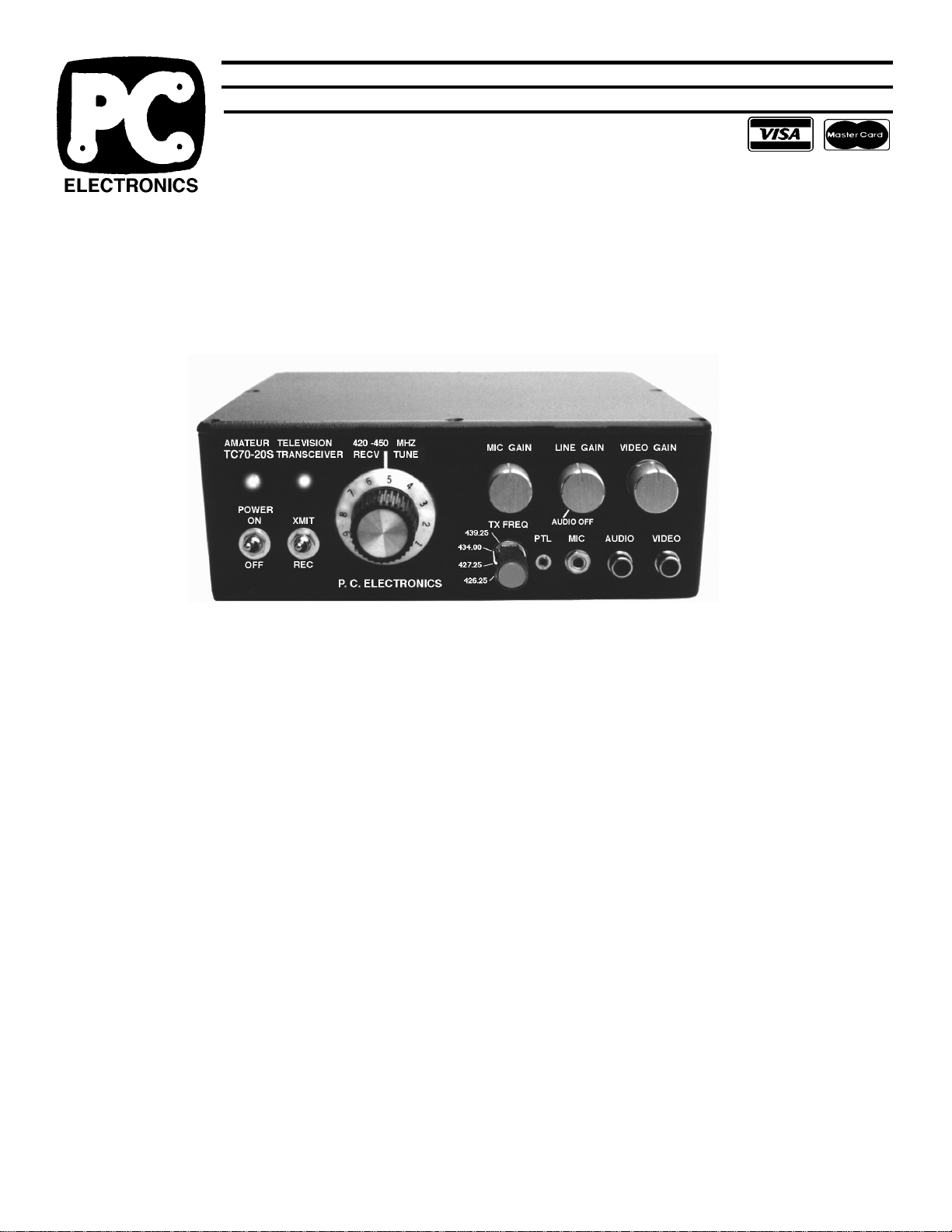
RECEIVE TUNE control varies the varicap voltage in the
VCO in the GaAsfet downconverter between 420 and 450
MHz (0 to 10 on the knob) in receive plus some overlap to
accommodate conversion down to TV channels 2, 3 or 4.
434 is between 3 and 5 on the knob into channel 3.
XMIT/REC switch. It is in parallel with the PTLjack. The red
lamp above this switch will light whenever you are in the
transmit mode and the green is lit in receive.
POWER ON switch turns on the applied +12 to 14 Vdc to the
TC70-20Sa. If the green receive light does not come on,
check the internal 5 Amp 3AG fuse and the reason for it to
blow before replacement. If the leads were reversed or an
overvoltage condition and fuses keep blowing, check the 16
Volt 5 Watt zener at the power on swtich and/or 78L08
regulatorontheTVC-2G fora short andreplace if necessary.
RF POWER OUT 250 Ohm pot on the end of the TXA5-70
exciterboard controls the drive to the M57716powermodule.
This is used to reduce the output power when driving an
external amplifier. See the procedure on page 5 and 7. You
must unplug any video input then set the TXA5-70S board 1K
pedestal pot CCW for maximum output first before adjusting
the peak power output, then reset the pedestal pot to 60% of
peak. Your Transceiver may go as high as 28 Watts at full RF
pot CW, but decreased linearity and sound sync buzz may
occurabove20 Watts. Goingfrom 20 to 28Wattsp.e.p. gives
insignificant change at the other end anyway.
INTERNAL CONTROLS
Your TC70-20Sa comes to you all set up to operate, do not
make any internal adjustments unless you have the proper
test equipment, tools and experience. The power is set for
22Watts p.e.p.with13.8Vdcapplied - a RF powermeterwill
show the blanking pedestal setup of 11 to 13 Watts with no
video applied, or less under video modulation. Refer to the
board layouts on pages 6 & 7 for pot locations. 3
OPERATING NOTES: ATV practices are somewhat different
from the other bands and modes. Since we must use
directional antennas to make up for the 23 dB higher noise
floordifferencecomparedtoNBFMduetoreceiverbandwidth
(15 kHz vs. 3 MHz), the probability of someone pointing their
beam at you while at the same time you at them and calling
CQ is very low. This is why many ATV contacts are initiated
by calling or listening on a 2 meter FM simplex ATV
coordinationfrequency(146.43for 434.0 &144.34for439.25).
Two meters, even for FM, has about 9 dB less path loss
than 70cm so that all possible ATVers can be received on 2
meter FM using just an omni antenna. You will find with
experiencethecorrelationbetween2 meter simplex and 70cm
ATV DX. It is much easier for all local ATVers to monitor a
squelched 2 meter FM simplex channel than to try tuning
andswingingthe70cmbeamlookingforsyncbarsorlistening
to TV speaker noise. Once another ATVer comes up on 2
meters,youcan roughlyswingthebeamson eachotherbefore
turning on the ATV transmitter. Then, if the picture is better
than 20% snow, the video transmitting station can talk on the
sound subcarrier, and all those receiving him can talk back at
thesametimeon 2 meters (full duplex) to comment on picture
content,etc. Otherslistening to the 2 meter channel are often
hooked into ATV this way. You can also run full duplex audio
and video with another ATV station on 33 or 23 cm.
It is more fun as time goes on to have many hams put their
families, other hobbies, and varied interests on the screen.
Let others know your 2 meterATV freq. by publishing in local
radio clubs, contact your localARRLSCM, or pick a night and
timeto start anATV net. TheTC70-20S is portableenoughto
give a little demo at your local radio club or hamfest.
IF YOU BELIEVE THE TC70-20Sa ISN’T WORKING, check
all cables, connections, power supply, internal fuse and the reverse
polarity 16volt protection zener connected to it, board test point DC
voltagesand VSWR. Ifyou reversed thepower cable, appliedmore
than 16 Vdc or close by lightning strike, the protection zener may
have shorted before the fuse blew. You can replace it with a Radio
Shack15V 1W zener. Measure theRF OutTPDC Voltage on page
7. Ifyou can’t determinethetrouble, callusand describetheproblem
or ask any questions you might have. It will save us both time if we
suggest some things to try that may have been over-looked, or for
us to better evaluate the problem. The TC70-20S can be repaired
by us for $75 plus parts cost in a few days if we believe the problem
is customer caused, or only your shipping cost to us if we determine
thatit wasdue to ourworkmanship andmaterials withinareasonable
time and given circumstances. Include with the unit your name, call,
streetaddress -no PO box- VisaorMastercard numbers,expiration
dateand exactnameas onthecard, andadescription ofthe problem.
There is no other warranty expressed or implied. See our latest
catalogue for our full service and return policies.
Other PC Electronics Transceiver manuals