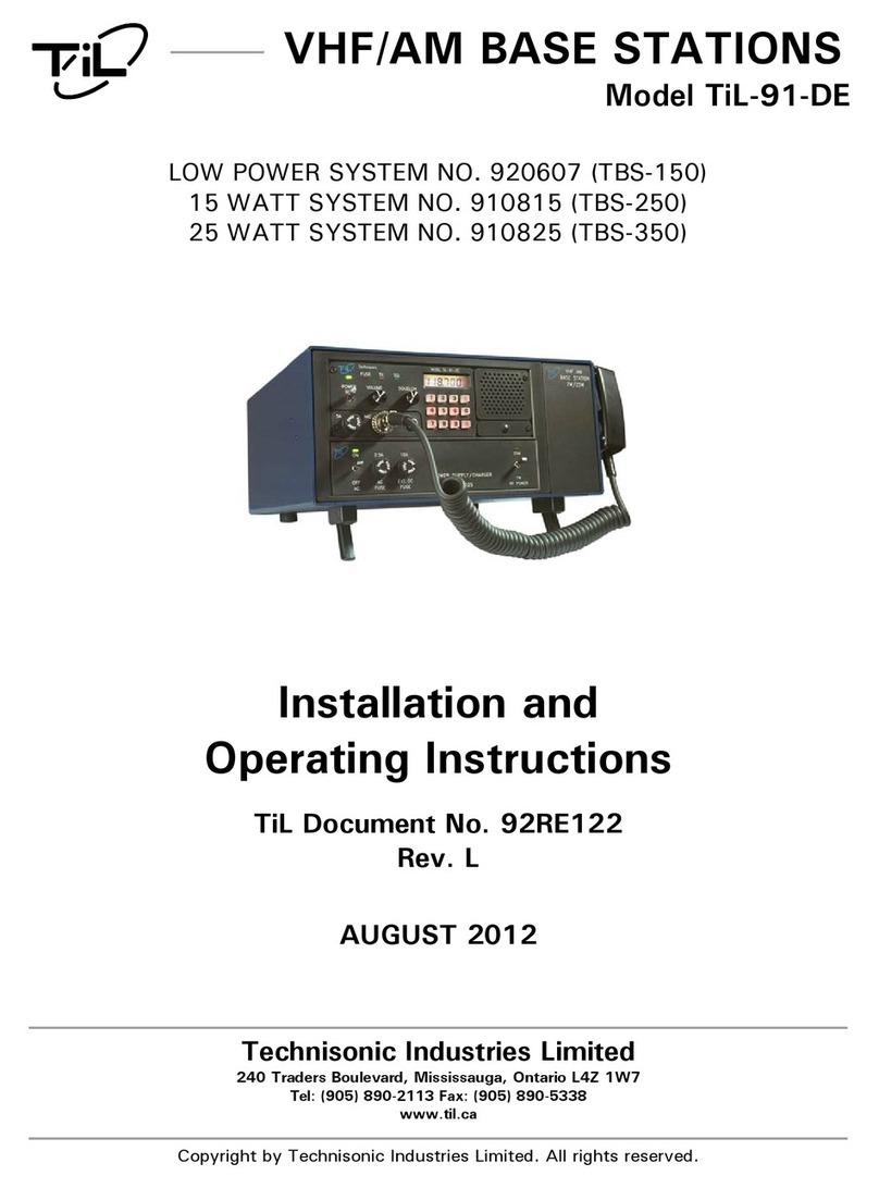
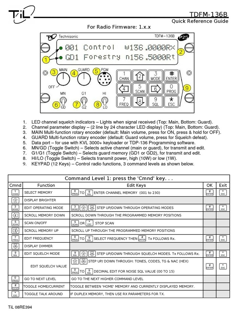
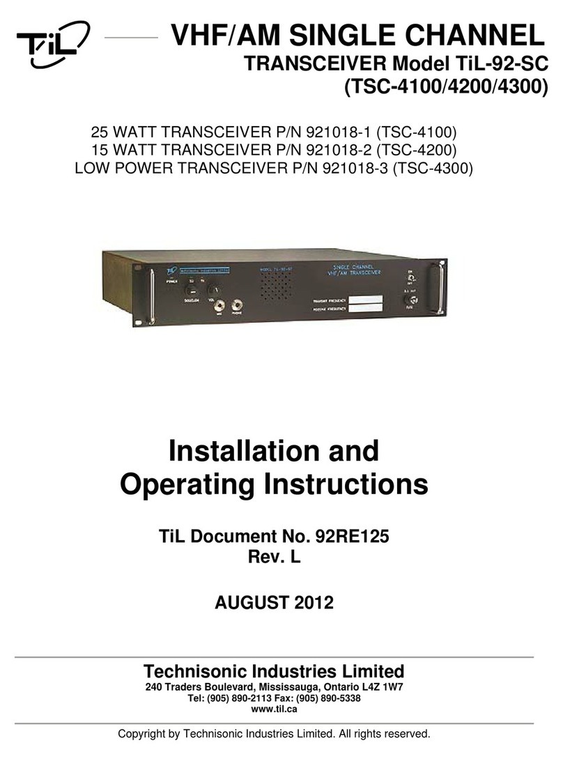
TIL TDFM-136B User manual

TDFM-136B
VHF/FM DIGITAL AIRBORNE TRANSCEIVER
OPERATING INSTRUCTIONS
Til Document: 08RE399
Rev. N/C
OCT 2010
Technisonic Industries Limited.
copyright © 2010 Technisonic Industries Ltd. All rights reserved.

TDFM-136B Operating In truction 08RE399
ii

08RE399 TDFM-136B Operating In truction
CONTACT US
Techni onic Indu trie Limited
240 Trader Blvd. E.
Mi i auga, Ontario.
L4Z 1W7
tel: (905) 890-2113
fax: (905) 890-5338
web: www.til.ca
SCOPE of MAN UAL
Thi document provide Operating In truction for TDFM-136B tran ceiver with firmware:
Release 1.0.0 Thi manual does not include tran ceiver in tallation in truction . For in tallation
in truction plea e ee Techni onic document: 08RE398.
FCC COMPL IANC E INFORMAT ION
Thi device complie with Part 15 of the FCC Rule . Operation i ubject to the following two
condition : (1) thi device may not cau e harmful interference and (2) thi device mu t accept any
interference received, including interference that may cau e unde ired operation.
W RNING: For compliance with FCC RF Expo ure Requirement , the mobile tran mitter antenna
in tallation hall comply with the following condition :
1. The tran mitter antenna gain hall not exceed 3 dBi.
2. The tran mitter antenna i required to be located out ide of a vehicle and kept at a
eparation di tance of 1.0 meter or more between the tran mitter antenna of thi device
and per on during operation.
NOTE: Thi equipment ha been te ted and found to comply with the limit for a Cla B digital device,
pur uant to Part 15 of the FCC Rule . The e limit are de igned to provide rea onable protection
again t harmful interference in a re idential in tallation. Thi equipment generate , u e , and can
radiate radio frequency energy and, if not in talled and u ed in accordance with the in truction
manual, may cau e harmful interference to radio communication . However, there i no guarantee
that interference will not occur in a particular in tallation. If thi equipment doe cau e harmful
interference to radio or televi ion reception, which can be determined by turning the equipment off
and on, the u er i encouraged to try to correct the interference by one or more of the following
mea ure :
-Re-orient or relocate the receiving antenna
-Increa e the eparation between the equipment and receiver
-Connect the equipment into an outlet or circuit different from that to which the receiver i
connected.
-Con ult the dealer or an experienced radio/TV technician for help.
W RNING:
Change or modification not expre ly approved by Techni onic Indu trie could void the
u er’ authority to operate the equipment.
WA RRANTY INFORMATION
The Model TDFM-136B, VHF/FM Digital Tran ceiver i under warranty for one year from date of
purcha e. Failed unit cau ed by defective part , or workman hip hould be returned to:
Techni onic Indu trie Limited
240 Trader Blvd. E,
Mi i auga, Ontario.
L4Z 1W7
iii

TDFM-136B Operating In truction 08RE399
Document Rev s on Table for 08RE399
Rev. /
Issue Page Descr pt on Date Change
By
iv

08RE399 TDFM-136B Operating In truction
Ta ble of C ontents
SECTION1 ......................................................................................................................................1
1.1 Control and Di play..............................................................................................................1
1.1.1 Front Panel Layout and Control ....................................................................................1
1.1.2 Channel Parameter Di play............................................................................................2
1.2 Tran ceiver Ba ic Operation..................................................................................................3
1.2.1 Selecting the Active Channel – Main or Guard...............................................................3
1.2.2 Selecting a Main Channel Memory.................................................................................4
1.3 About Command ..................................................................................................................5
1.3.1 Command Level ............................................................................................................5
1.3.2 Command Type ............................................................................................................6
1.3.3 Command Group ..........................................................................................................6
1.3.4 Command Reference.....................................................................................................6
SECTION 2 .....................................................................................................................................7
2.1 Channel Operating Parameter .............................................................................................7
2.1.1 Memory Parameter .......................................................................................................7
2.2 Editing Channel Operating Parameter .................................................................................7
2.2.1 The Frequency Parameter..............................................................................................9
2.2.2 Operating Mode ..........................................................................................................10
2.2.3 Squelch Mode .............................................................................................................11
2.2.4 ID Call Operation..........................................................................................................15
2.3 Scan and Multi-Mode Operation ..........................................................................................16
2.3.1 Scan Operation............................................................................................................16
2.3.2 Multi-Mode Operation...................................................................................................17
2.4 Controlling U er Acce ......................................................................................................18
2.4.1 Control Acce to Command Level .............................................................................18
2.4.2 Set Command Permi ion ..........................................................................................19
2.4.3 Control Acce to Squelch Mode ................................................................................21
2.4.4 Control Editing of Memorie .........................................................................................21
2.4.5 Control Di play of Frequency Information.....................................................................22
2.5 Encrypted Operation ...........................................................................................................23
2.5.1 Loading Encryption Key ..............................................................................................23
2.5.2 A ign KeyTag to Encryption Key ...............................................................................23
2.5.3 A ign Key by KeyTag to Memory................................................................................24
2.5.4 Enable/Di able Encrypted Operation............................................................................26
SECTION 3 ....................................................................................................................................27
3.1 Operator Level 1 Command ..............................................................................................28
3.1.1 Select the Operating Memory for the Main Channel.....................................................28
3.1.2 Increa e Di play Brightne .........................................................................................28
3.1.3 Edit Channel Operating Mode......................................................................................28
3.1.4 Scroll Backward through Available Memorie .............................................................29
3.1.5 Start/Stop Scan............................................................................................................29
v

TDFM-136B Operating In truction 08RE399
3.1.6 Scroll Backward through Available Memorie .............................................................30
3.1.7 Edit Channel Operating Frequency...............................................................................30
3.1.8 Decrea e Di play Brightne ........................................................................................31
3.1.9 Edit Channel Squelch Mode.........................................................................................31
3.1.10 Command Level Up....................................................................................................34
3.1.11 Toggle memory: current/home....................................................................................34
3.1.12 Toggle Talk Around.....................................................................................................34
3.1.13 Era e Encryption Key ...............................................................................................34
3.2 Operator Level 2 Command ...............................................................................................34
3.2.1 Create/Edit All Channel Information .............................................................................35
3.2.2 Copy Guard to Main ....................................................................................................36
3.2.3 Lock Keypad ................................................................................................................36
3.2.4 Not U ed...................................................................................................................... 36
3.2.5 Edit Scan Li t & Enable/Di able Scan..........................................................................36
3.2.6 Edit Memory Text De cription.......................................................................................37
3.2.7 Create Shadow Memory...............................................................................................38
3.2.8 Copy Main to Guard ....................................................................................................39
3.2.9 Encryption ON/OFF......................................................................................................39
3.2.10 Command Level Up ...................................................................................................40
3.2.11 Command Level Down................................................................................................40
3.2.12 L2–#. Not U ed..........................................................................................................40
3.3 Operator Level 3 Command ...............................................................................................40
3.3.1 Select Boot Channel.....................................................................................................40
3.3.2 A ign Key by KeyTag..................................................................................................41
3.3.3 Di play Firmware Relea e and Ver ion Information.....................................................42
3.3.4 Di play Firmware Relea e and Ver ion Information.....................................................42
3.3.5 Edit Scan Parameter ...................................................................................................43
3.3.6 Configure PTT Timer....................................................................................................44
3.3.7 Side Tone Audio Level Adju t.......................................................................................45
3.3.8 PC Data Upload/Download ..........................................................................................45
3.3.9 Di play Channel Squelch Parameter ..........................................................................46
3.3.10 Command Level Up ...................................................................................................46
3.3.11 Command Level Down................................................................................................46
3.3.12 L3-# not u ed ............................................................................................................46
3.4 Maintenance Command (Level 4).....................................................................................47
3.4.1 Set Default Record.......................................................................................................47
3.4.2 Set Re tricted Level Acce Mode...............................................................................48
3.4.3 Set Command Permi ion ..........................................................................................48
3.4.4 Set Memory Edit...........................................................................................................49
3.4.5 L4-5. not u ed.............................................................................................................50
3.4.6 L4-6. not u ed.............................................................................................................50
3.4.7 Set Frequency Di play.................................................................................................50
3.4.8 A ign KeyTag to Encryption Key .............................................................................50
3.4.9 Set Squelch Re triction ..............................................................................................52
3.4.10 Command Level Up....................................................................................................53
3.4.11 Command Level Down................................................................................................53
3.4.12 L4-# not u ed.............................................................................................................53
3.5 Supervi or Command (Level 5).........................................................................................54
3.5.1 L5-1 not u ed...............................................................................................................54
3.5.2 L5-2 not u ed...............................................................................................................54
3.5.3 L5-3 not u ed...............................................................................................................54
vi

08RE399 TDFM-136B Operating In truction
3.5.4 Re-Set Databa e to Factory Default ...........................................................................54
3.5.5 L5-5 not u ed...............................................................................................................55
3.5.6 Tran parent Mode........................................................................................................55
3.5.7 Edit Pa word .............................................................................................................55
3.5.8 Run Bootloader............................................................................................................56
3.5.9 Set Unit ID (UID)...........................................................................................................56
3.5.10 L5-0 not u ed.............................................................................................................57
3.5.11 Command Level Down................................................................................................57
3.5.12 L5-# not u ed.............................................................................................................57
SECTION 4 ....................................................................................................................................59
4.1 Appendix A. In talling the Jumper for Re tricted Level Acce ............................................59
4.2 Appendix B. CTCSS Tone and DCS Code Table ................................................................60
4.3 Appendix C. Programming Channel data u ing TDP and a PC............................................61
4.4 Appendix D. 2.5 kHz & 6.25 kHz Valid Frequencie .............................................................63
4.5 Appendix E. Default Table ..................................................................................................64
vii

TDFM-136B Operating In truction 08RE399
Ta ble of F gures
Figure 1-1. The TDFM-136 front panel howing control & di play feature ..................................... 1
Figure 1-2. The TDFM-136 di play – unique parameter highlighted...............................................2
Figure 1-3. The TDFM-136 di play - common channel parameter highlighted................................2
Figure 1-4. The active channel di play and control point ................................................................3
Figure 1-5. Control point for electing an active memory for the MAIN channel..............................4
Figure 1-6. The Screen howing 'Level 3” in the Command Level Di play Po ition..........................5
Figure 2-1. The u er creen to edit the Main frequency....................................................................8
Figure 2-2. The u er creen to edit the Guard frequency.................................................................8
Figure 2-3. The u er creen to edit the Main frequency for receive..................................................9
Figure 2-4. The u er creen to edit the Main frequency for tran mit.................................................9
Figure 2-5. The u er creen to edit the Main Operating Mode........................................................10
Figure 2-6. The creen to edit the Main Squelch Mode for receive.................................................12
Figure 2-7. The noi e quelch edit creen......................................................................................13
Figure 2-8. The creen to edit the Main Squelch Mode for tran mit................................................13
Figure 2-9. The CTCSS Tone quelch edit creen..........................................................................13
Figure 2-10. The DCS Code quelch edit creen...........................................................................14
Figure 2-11. The digital NAC quelch edit creen...........................................................................14
Figure 2-12. The digital TalkGroup quelch edit creen..................................................................15
Figure 2-13. The digital ID Call quelch edit creen........................................................................15
Figure 2-14. The Set Unit ID edit creen.........................................................................................16
Figure 2-15. Identifying Graphic for Primary Channel with Shadow ..............................................18
Figure 2-16. Identifying Graphic for Shadow Channel....................................................................18
Figure 2-17. The creen to enter a pa word for re tricted level acce ........................................19
Figure 2-18. The creen to et the Maintenance pa word............................................................19
Figure 2-19. The Screen to Edit the Level 1 Permi ion ...............................................................20
Figure 2-20. The Screen howing Mode Select re triction for Analog Receive.............................21
Figure 2-21. The creen for Enabling/Di abling edit of a pecific Memory......................................21
Figure 2-22. The error creen on trying to edit a di abled memory.l...............................................22
Figure 2-23. The creen for Enabling/Di abling Frequency Di play for a pecific Memory.............22
Figure 2-24. The creen howing memory with frequency di play di abled...................................22
Figure 2-25. The creen to elect the SLN to a ign the KeyTag to...............................................23
Figure 2-26. The creen to edit the KeyTag....................................................................................24
Figure 2-27. The creen to a ign another KeyTag or exit..............................................................24
Figure 2-28. Select the Main memory to a ign the key to.............................................................25
Figure 2-29. Select the KeyTag to a ign to the memory................................................................25
Figure 2-30. Select decrypt on Any Key or A igned Key...............................................................25
Figure 2-31. The creen to a ign another key or exit....................................................................26
Figure 2-32. The analog memory encryption error creen..............................................................26
Figure 2-33. The error creen for no encryption key a igned........................................................26
Figure 2-34. The Encryption Enabled for Main memory creen......................................................26
Figure 3-1. The U er Screen to Enter a Memory Number...............................................................28
Figure 3-2. The U er Screen to Edit the Operating Mode...............................................................28
Figure 3-3. Trying to tart can on a Channel with Scan di abled..................................................29
Figure 3-4. Start can on a Channel with Scan enabled.................................................................29
Figure 3-5. The U er Screen to Edit the Main frequency................................................................30
Figure 3-6. Editing the Squelch Mode.............................................................................................31
Figure 3-7. Editing the Noi e Squelch Value...................................................................................31
Figure 3-8. Selecting the CTCSS Tone Value.................................................................................32
Figure 3-9. Selecting the DCS Code Value.....................................................................................32
Figure 3-10. Editing the P25 TalkGroup Value................................................................................32
viii

08RE399 TDFM-136B Operating In truction
Figure 3-11. Editing the P25 NAC Value.........................................................................................33
Figure 3-12. Editing the P25 ID Call Value......................................................................................33
Figure 3-13. The Screen to Enter a Scan Li t or Enable/Di able Scan...........................................37
Figure 3-14. The Screen Showing Scan Enabled for thi Memory..................................................37
Figure 3-15. Editing the Text De cription........................................................................................37
Figure 3-16. Entering a Primary Memory for the Shadow Channel.................................................38
Figure 3-17. Entering a Shadow Channel Memory Number...........................................................38
Figure 3-18. Edit the Shadow Memory Parameter - Text................................................................39
Figure 3-19. The Encryption Enabled for Main...............................................................................39
Figure 3-20. Selecting Main Channel Boot Memory.......................................................................40
Figure 3-21. Selecting the Memory to A ign the Key to................................................................41
Figure 3-22. Selecting the KeyTag to A ign to the Memory...........................................................41
Figure 3-23. Selecting the decrypt option: Any Key or A igned Key..............................................41
Figure 3-24. Screen to A ign another key or exit..........................................................................42
Figure 3-25. Selecting Edit mode...................................................................................................42
Figure 3-26. Showing the Code Relea e Information.....................................................................42
Figure 2-27. Select the Scan Revert Mode.....................................................................................43
Figure 2-28. Set the Scan Reply Timer Value.................................................................................43
Figure 3-29. Set the Scan Monitor Timer Value..............................................................................44
Figure 3-30. Set the Scan Delay Timer Value.................................................................................44
Figure 3-31. Set the PTT Timer Value.............................................................................................44
Figure 3-32. Set the Side tone Audio Level....................................................................................45
Figure 3-33. Upload/Download Memory Data to/from the PC.........................................................45
Figure 3-34. Di play of the Receive Squelch Parameter Value .....................................................46
Figure 3-35. Di play of the Tran mit Squelch Parameter Value ....................................................46
Figure 3-36. Select the Acce Mode from a li t.............................................................................48
Figure 3-37. Edit the Level 1 Permi ion ......................................................................................48
Figure 2-38. Edit the Level 2 Permi ion ......................................................................................48
Figure 3-39. Edit the Level 3 Permi ion ......................................................................................48
Figure 3-40. Enable/Di able edit of a pecific Memory...................................................................49
Figure 3-41. The Frequency Di play Enable/Di able creen..........................................................51
Figure 3-42. A memory with frequency di play di abled.................................................................50
Figure 3-43. Step through available key by SLN...........................................................................51
Figure 3-44. The creen to edit the KeyTag....................................................................................51
Figure 3-45. The creen to a ign another KeyTag or exit..............................................................51
Figure 3-46. The Screen to Set Available Squelch Mode for Analog Receive...............................52
Figure 3-47. The Screen to Re trict Editing of the Noi e Squelch Value........................................53
Figure 3-48. The Screen to Re trict Available CTCSS Tone .........................................................53
Figure 3-49. Re trict Available DCS Code ....................................................................................53
Figure 3-50. Era e and Re-Program to Factory Default ................................................................54
Figure 3-51. Tran parent Mode......................................................................................................55
Figure 3-52. Edit Maintenance Pa word.......................................................................................55
Figure 3-53. Edit Supervi or Pa word..........................................................................................56
Figure 3-54. The Bootloader Screen...............................................................................................56
Figure 3-55. Set Unit ID Number ( creen for Main hown).............................................................56
Figure 4-1. The Screw Po ition to remove the Left Hand Side Panel............................................59
Figure 4-2. The Shunt Po ition to Enable Re tricted Level Acce ................................................59
Figure 4-3. The Communicate with PC Command Screen.............................................................61
Figure 4-4. The TDP-136 Radio Programming Software Window...................................................61
ix

TDFM-136B Operating In truction 08RE399
Tab le o f Tab les
Table 2-1. Tran ceiver Operating Mode ........................................................................................10
Table 2-2. Receive and Tran mit Squelch Mode ...........................................................................11
Table 2-3. Permi ion Applicability by Command and Level...........................................................20
Table 2-4. Squelch Mode Re triction ............................................................................................21
Table 3-1. Command Level Reference...........................................................................................27
Table 3-2. Tran ceiver Operating Mode ........................................................................................29
Table 3-3. Receive and Tran mit Squelch Mode ...........................................................................31
Table 3-4. Extra Character for Text Edit........................................................................................38
Table 3-5. The Channel Template Factory Default ........................................................................47
Table 3-6. Permi ion Applicability wrt Command Level ...............................................................49
Table 3-7. Squelch Mode that can be Re tricted...........................................................................51
Table 4-1. CTCSS Tone ................................................................................................................60
Table 4-2. DCS Code ....................................................................................................................60
Table 4-3. Valid Frequency Pattern.................................................................................................63
Table 4-4. Memory Template Factory Default ................................................................................64
Table 4-5. Configuration Parameter Default Value ........................................................................64
Table 4-6. Scan Parameter Default Value .....................................................................................64
Table 4-7. Unit Identification (UID) Default Value ..........................................................................64
Table 4-8. Re tricted Level Pa word Default Value .....................................................................64
x

TDFM-136B Operating In truction 08RE399
S E C T I O N 1
INTROD UCT ION
Thi ection provide an overview of the ba ic tran ceiver operation, it i broken into three
ub ection a follow :
•an overview of the control and di play information
•a de cription of ba ic u e of the tran ceiver
•an introduction to the tran ceiver command function
1.1 Controls and D splay
Thi ection provide ba ic information on the control and di play information provided for the u er
on the front panel of the tran ceiver.
1.1.1 Front Panel Layout and Controls
All the u er interface control and di play information are available to the u er on the front panel of
the tran ceiver, with the exception of the PTT control, which i activated by an external button. The
front panel layout of the TDFM-136B i hown in figure 1-1 below.
Figure 1-1. The TDFM-136B front panel howing control & di play feature .
The control and di play feature are identified a follow :
1. LED channel quelch indicator – light on ignal received (top=Main, bottom=Guard).
2. Channel parameter di play – two line by 24 character LED di play (top=Main, bottom=Guard).
3. Power ON/OFF witch and Main channel volume control (rotary encoder, with p/b witch).
4. Guard channel volume control (rotary encoder with p/b witch) and Squelch defeat.
5. Data port – for u e with KVL 3000+ keyloader or TDP-136 Programming oftware.
6. Main/Guard witch (toggle) – elect active channel (main or guard), for tran mit and edit.
7. Guard 1 or 2 witch (toggle) – elect guard memory (GD1 or GD2), for tran mit and edit.
8. Tran mit Power witch (toggle) – elect tran mit power, high (10W) or low (1W).
9. Keypad (12 pu h button ) – control other tran ceiver feature (de cribed below).
Techni onic Indu trie Ltd. 1

08RE399 TDFM-136B Operating In truction
1.1.2 Channel Parameter D splay
Figure 1-2 below how the di play of the unit, and identifie the individual parameter
hown for each of the main and guard channel .
Figure 1-2. The TDFM-136B di play – unique parameter highlighted.
The parameter that are pecific to one channel or are not channel related are identified in figure
1-2 above. Item 1 – 6 fall into thi category, they are de cribed a follow :
1. Main channel information i di played on the top row of the di play.
2. Guard channel information i di played on the bottom row of the di play.
3. The Main channel can have up to 230 memory po ition (001 to 230), the current active memory
number for the Main channel i hown in the fir t three character of the line.
4. The Guard channel can have two memorie , GD1 and GD2, the currently active Guard memory
number i hown in the fir t three line of the bottom row.
5. Memorie for the Main channel can be canned, when in u e, can information i hown at the
4th character po ition on the top row.
6. On the bottom row, the 4th character po ition i u ed for different purpo e : it will indicate the
current command level a well a howing the lock icon () if the keypad acce ha been
locked out.
7.
Figure 1-3 below how the di play of the unit, and identifie tho e parameter that are
common to both main and guard channel .
Figure 1-3. The TDFM-136B di play - common channel parameter highlighted.
2 Techni onic Indu trie Ltd.

TDFM-136B Operating In truction 08RE399
The common parameter are identified a item 7 through 11 and are a follow :
7. Up to eight character are available for a text de cription of the memory.
8. One character po ition i u ed to indicate the operating mode:
Analog mode : wide "w"(25kHz.), narrow "n" (12.5kHz.)
Digital mode: project 25 digital "D" (12.5kHz.).
9. Eight character are u ed to indicate the frequency in u e.
10. One character indicate either Receive or Tran mit a : "R" or "T".
11. The final character indicate the current quelch mode:
Analog mode : noi e quelch "x", CTCSS tone "t", or DCS code "c"
Digital mode : monitor "m", NAC only "n", TalkGroup + NAC "g"
1.2 Transce ver Bas c Operat on
For ba ic operation of the tran ceiver the u er ha the yolk mounted PTT key and memory
up/down key (if connected) in addition to the control di cu ed previou ly. Ba ic
operation i di cu ed in thi ection.
1.2.1 Select ng the Act ve Channel – Ma n or Guard
When the u er pre e 'PTT', the unit will tran mit with the parameter of the active channel and
memory, that the u er ha elected. The method of electing MAIN or GUARD channel i
de cribed below.
Figure 1-4. The active channel di play and control point .
1. The MAIN channel data i hown on the top line of the di play, MAIN upport 230
memory po ition (001 to 230). The MAIN channel i made the active channel for
tran mit and edit by the u er placing the MN/GD witch in the MN po ition. For
electing the active memory for the MAIN channel, ee the following ection.
2. When the MN/GD witch i in the GD po ition then the GUARD channel i active. The
GUARD channel ha two fixed memorie : GD1 and GD2, the GUARD memory u ed i
determined by the po ition of the G1/G2 witch.
Techni onic Indu trie Ltd. 3

08RE399 TDFM-136B Operating In truction
1.2.2 Select ng a Ma n Channel Memory
For the MAIN channel there are 230 po ible memory po ition to choo e from (001 to 230), the
method of electing a memory for the MAIN channel i de cribed below.
Figure 1-5. Control point for electing an active memory for the MAIN channel.
There are everal way in which the u er can control the active memory for the MAIN channel:
1. Pre the 'CHAN' button (1), and then directly enter the three digit memory number.
2. Pre and hold either the back arrow (4), or the forward arrow(6) button, and the unit will croll
through the exi ting (already programmed) memorie .
3. Pre the 'ENTER' button (#), and the unit' Main channel will toggle between the current
memory and the de ignated 'home' memory. If no 'home' memory ha been elected, then the
default i channel 1.
Note on crolling:
•memory number that have not been created will be kipped.
•the croll will wrap both up and down (. . . 230 ↔ 001. . . ).
Example:
The u er ha memorie 001, 002, 004, 010, 024, 100 and 151 programmed into the tran ceiver.
The MAIN channel i elected, and the active memory i 004. No home memory ha been
defined, o the default i 001.
If the back arrow i pre ed and held, the MAIN di play will croll to memory 002, then to 001, and
then to 151, the equence will continue until the u er relea e the key.
For the Main channel, if the u er pre e the “ENTER” button, then the MAIN channel will jump to
memory “001”, if the Main memory wa omething other than “001”, then pre ing “ENTER” again
will return to that memory.
4 Techni onic Indu trie Ltd.

TDFM-136B Operating In truction 08RE399
1.3 About Commands
The tran ceiver upport command to provide more advanced control and configuration
feature . A command i imply a key pre , or erie of key pre e , that cau e the unit to
perform a function. Thi ection provide an overview of the command architecture.
1.3.1 Command Levels
In order to accommodate all the command required to provide the nece ary operation,
command have been divided up into level (abbreviated a 'L1', 'L2' etc). Thi re ult in the mo t
common command needing the fewe t key pre e to acce .
There are five command level in all, three of which are available to the operator (Operator
Command ). For each command level up to 10 command are available: 1-9, and '#'. Note: for
command level 1 (L1) only, the ESC (*) button ha an a ociated function a you cannot go a level
down. The zero (0), and the ESC (*) key are re erved to move between the command level a
follow :
step up through command levels
step down through command levels
When tepping through command level , the level i hown a a ub cript digit in the 4th character
po ition on the lower line of the di play, ee figure. Note that thi di play po ition i left blank for
the default level (L1).
Figure 1-6. The Screen howing 'Level 3” in the Command Level Di play Po ition
The Operator Command level 2 and 3 (L2 & L3) are 'time limited', if the u er get into one of
the e command level and doe not enter a command within 5 econd , the unit automatically
return to command level 1.
Note that after exiting a L2 or L3 command, the timer i re et to 5 econd , o if you want to return
to level 1 immediately, you have to pre level down key ('ESC' or '*'). Thi allow you to perform
another command on that level without having to tart over from level 1.
In addition to the three command level available to the operator, the unit can be put into a mode
that allow acce to maintenance and upervi or command . The e re tricted command level
(L4 & L5) are to allow authorized per onnel to et operating policy for the radio through u e of
'Permi ion ', and perform other maintenance and configuration function ; the e are explained
later in the manual.
The restricted command levels (L4 and L5) should NEVER be enabled in flight. Incorrect
use could render the unit non-functional! These levels exist for configuration and
maintenance use only.
Techni onic Indu trie Ltd. 5

08RE399 TDFM-136B Operating In truction
1.3.2 Command Types
There are two ba ic type of command : inherent, and interactive:
Inherent commands
The e are imple 'one-touch' command , they do not need any further input from the u er.
Example: the di play brightne control command (up/down arrow , key 2 & 8)
Interactive commands
The e command require further input from the u er, and they mu t end a follow :
accept the entry and ex t
abandon the entry and ex t
Example: the 'Frequency' command require that the u er enter a frequency, before exiting.
1.3.3 Command Groups
The command can be characterized a belonging to one of three group :
Operating command are tho e which perform a function directly related to the u e of the radio.
Edit command allow the u er to Edit the RF channel parameter (frequency, mode etc).
Configuration command affect how the radio operate , including how other command work.
1.3.4 Command Reference
Throughout the manual the command will be referred to by level and number to make it clear what
command i being referenced. The hort form u ed i a follow :
Level - abbreviated a 'L' followed by a number, a da h eparator, and a command number.
Examples:
The 'edit frequency' command i : level one, command number 7. So the hort form i : L1-7. Since
under normal circum tance the tran ceiver i in level 1, to acce the command imply pre '7'.
Level two, command number 3 i hown a : L2-3. To get to thi command you mu t fir t go to
level 2 (by pre ing the '0' key), then enter the command key, '3'.
6 Techni onic Indu trie Ltd.

TDFM-136B Operating In truction 08RE399
S E C T I O N 2
TRANSCEI VER OPERATI ON
Thi ection de cribe operating the tran ceiver including u ing the command function to
perform common ta k . Thi ection provide more advanced information about
operating the tran ceiver, tarting with the ba ic and moving through the more advanced
feature .
2.1 Channel Operat ng Parameters
A de cribed in the previou ection the tran ceiver upport two (2) channel : Main and
Guard. Each of the e channel operate u ing the parameter of the currently elected
memory for that channel.
The Main channel operate u ing the parameter of the currently active main memory, and
there can be up to 230 memorie available to the Main channel. Main memory number 001
mu t alway exi t, and i the default Main memory when the unit i hipped.
Similarly the Guard channel operate u ing the parameter of the currently active Guard
memory. The difference i that the Guard channel upport only two memorie : GD1 and
GD2, the e may be elected via the front panel G1/G2 witch, both of the e memorie
mu t exi t and are programmed from the factory.
The parameter for any factory programmed memory may be changed by the u er.
2.1.1 Memory Parameters
Each memory ha a variety of parameter that may be edited by the u er including:
•frequency – 8 character
•operating mode – 1 character
•quelch mode and quelch mode value – 1 character di played
•text de cription – up to 8 character
•can li t – 1 character
The ability to edit ome of the e may be re tricted under certain operating condition .
Example: while can i available for any Main channel memory, the u er may not et scan
parameter for either Guard channel, or for ' hadow' channel on the Main channel.
2.2 Ed t ng Channel Operat ng Parameters
There are two way to change the operating parameter for the memorie u ed by either
the main or guard channel: edit from the tran ceiver front panel, or edit u ing the PC
programming oftware. Thi ection will de cribe the fir t option; PC programming i
di cu ed in Appendix C.
From the front panel, the u er can edit any of the parameter (li ted above) for the active
channel u ing the individual parameter edit function .
Techni onic Indu trie Ltd. 7

08RE399 TDFM-136B Operating In truction
In addition to editing the memory parameter individually, the u er can create new
memorie (for the main channel only) or edit all the parameter of an exi ting memory (for
Main or Guard channel ).
All edit command are interactive command (they expect input from the u er), a uch, the
line on the di play that doe not have the parameter to be edited, become a prompt line to
guide the u er a to the valid key for that edit.
Example: The edit frequency command, figure 2-1 how the edit frequency creen if the
active memory i 001 on Main. Note that a cur or fla he on the econd character in the
frequency field , on the Main di play (top row) and that the Guard Di play (bottom row)
ha been changed to a prompt line . Thi prompt provide the u er with information uch
a what command i running, and what key are valid.
F gure 2-1. The user screen to ed t the Ma n frequency
When the Guard Channel i active, the ituation i rever ed: the cur or i placed on the
econd digit in the frequency field on the Guard line, and the top line become the
prompt line.
F gure 2-2. The user screen to ed t the Guard frequency
Calling Key.
Some editor imply allow the u er to elect a et value from a li t; in the e ca e , the key
u ed to 'call' the editor will al o tep up through the available choice . Thi allow the u er
to make a election without having to further navigate the keypad.
Simplex and duplex parameters.
Some of the tran ceiver parameter are implex only: they are the ame for both tran mit
and receive operation. Other parameter are duplex: the e may be (but do not have to be)
different for tran mit than they are for receive.
ccept and Continue / ccept and Exit
For many edit function (example Operating Mode), once the u er ha elected a value,
pre ing the key will accept the entry and exit the editor. However, ome edit function
require that the u er accept a value before advancing (example Squelch Mode), in the e
ca e pre ing the key will advance to the next point in the editor.
bandon Edit
In all ca e , the key will abandon the edit with no change made.
8 Techni onic Indu trie Ltd
!"#$%&'
1
2
1
2
!"#$%&'
2
1
21

TDFM-136B Operating In truction 08RE399
2.2.1 The Frequency Parameter
The TDFM-136 upport frequencie in the range 136.0000, to 174.0000 MHz. Frequencie in the
analog wide band (25 kHz. channel pacing), the analog narrow band (12.5 kHz. Channel
pacing), and the P25 band (Pha e 1 – 12.5 kHz. channel pacing) can be entered at any 2.5 kHz
tep. In addition, frequencie can be entered on the frequencie propo ed for P25 Pha e 2. Note
that thi doe not mean that the tran ceiver operate in thi mode (6.25 kHz. channel pacing), ju t
that the tran ceiver can be tuned to tho e frequencie ; the channel pacing will till be either 25
kHz. or 12.5 kHz. See appendix D for the 6.25 kHz frequencie upported.
Frequency i a implex/duplex parameter, that i , the unit can tran mit and receive on the ame
frequency or it may be configured o that the tran mit frequency and receive frequency are
different.
Editing Frequencies
The edit frequency command i ea ily acce ible, it i command L1-7. To acce thi command,
imply pre '7', on the front panel keypad. Notice that the key i al o marked “FREQ”.
Thi command allow the u er to edit the operating frequency of the elected channel & memory.
The frequency will be edited in duplex mode: fir t Receive, then Tran mit. Upon tart, the cur or
appear at the econd character in the Frequency field of the channel to be edited. The edit creen
appear a follow :
F gure 2-3. The user screen to ed t the Ma n frequency for rece ve
The u er may now enter the de ired operating frequency a follow :
to dec mal mode: enter number, cursor automat cally advances
accept the entry and cont nue
abandon the entry and ex t
The editor will not accept a value out ide the limit of 136.0000 MHz. to 174.0000 MHz. In addition
frequency upport 2.5 kHz increment , and valid 6.25 kHz channel pacing frequencie in all
Operating mode . See appendix N for valid 6.25 kHz frequencie .
Once the receive parameter i entered, the 2nd la t character in the di play will witch from “R” to
“T”, the u er can now enter the tran mit value. Note that the receive value i automatically entered,
o to get implex operation, imply accept thi entry.
F gure 2-4. The user screen to ed t the Ma n frequency for transm t
When complete, accept the entry if it i correct, or e cape to exit without aving.
Techni onic Indu trie Ltd. 9
!"#$%&'
(
!"#$%&'

08RE399 TDFM-136B Operating In truction
2.2.2 Operat ng Modes
The operating mode i defined a the RF channel pacing and modulation type u ed for the
elected channel/memory on the tran ceiver.
The unit upport three operating mode : Analog wide, analog narrow, and P25 digital. In the
analog wide mode, the radio i operating on 25kHz. channel pacing, on both analog narrow, and
in P25 digital mode, the radio operate with 12.5kHz. channel pacing. In analog mode the
tran ceiver operate u ing tandard frequency modulation, in the P25 mode the unit u e C4FM.
Table 2-1 how the available Operating Mode , the bandwidth, and the indicating character u ed.
Table 2-1 Transce ver Operat ng Modes
Operat ng Mode Bandw dth Ind cator
Analog Wide 25 kHz 'w'
Analog Narrow 12.5 kHz 'n'
P25 Digital 12.5 kHz 'D'
The u er can ea ily witch between mode on any memory for any channel (ie any Main memory,
and both Guard1 and Guard2). Since the quelch mode are not common acro analog and
digital operating mode , if you change between the e mode , the Squelch Mode will be affected
(for more on thi ee 'Squelch Mode ' below).
The operating mode i a implex parameter.
Editing Operating Mode
The edit operating mode command i ea ily acce ible, it i command L1-3. To acce thi
command, imply pre '3', on the front panel keypad. Notice that the key i al o marked “MODE”.
Thi command allow the u er to edit the operating mode of the elected channel & memory. Since
operating mode i implex only, the editor i very imple. Upon tart, the cur or appear at the
operating mode character field of the channel to be edited. The edit creen appear a follow :
F gure 2-5. The user screen to ed t the Ma n Operat ng Mode.
You may now edit the Operating Mode a follow :
step up/down through ava lable operat ng modes (w, n, D)
accept the entry and ex t
abandon the entry and ex t
10 Techni onic Indu trie Ltd
!)*$%&'
Other manuals for TDFM-136B
2
Table of contents
Other TIL Transceiver manuals
