PCB Piezotronics RHM240A02 User manual

Model RHM240A02
Uniaxial ICP® Strain Sensor
Installation and Operating Manual
For assistance with the operation of this product,
contact PCB Piezotronics, Inc.
Toll-free: 800-828-8840
24-hour SensorLine: 716-684-0001
Fax: 716-684-0987
E-mail: [email protected]
Web: www.pcb.com

Manual 21354 Rev E
ECN 50523
Repair and Maintenance
PCB guarantees Total Customer Satisfaction through its
“Lifetime Warranty Plus” on all Platinum Stock Products
sold by PCB and through its limited warranties on all other
PCB Stock, Standard and Special products. Due to the
sophisticated nature of our sensors and associated
instrumentation, field servicing and repair is not
recommended and, if attempted, will void the factory
warranty.
Beyond routine calibration and battery replacements
where applicable, our products require no user
maintenance. Clean electrical connectors, housings, and
mounting surfaces with solutions and techniques that will
not harm the material of construction. Observe caution
when using liquids near devices that are not hermetically
sealed. Such devices should only be wiped with a
dampened cloth—never saturated or submerged.
In the event that equipment becomes damaged or ceases
to operate, our Application Engineers are here to support
your troubleshooting efforts 24 hours a day, 7 days a
week. Call or email with model and serial number as well
as a brief description of the problem.
Calibration
Routine calibration of sensors and associated
instrumentation is necessary to maintain measurement
accuracy. We recommend calibrating on an annual basis,
after exposure to any extreme environmental influence,
or prior to any critical test.
PCB Piezotronics is an ISO-9001 certified company whose
calibration services are accredited by A2LA to ISO/IEC
17025, with full traceability to SI through N.I.S.T. In
addition to our standard calibration services, we also offer
specialized tests, including: sensitivity at elevated or
cryogenic temperatures, phase response, extended high
or low frequency response, extended range, leak testing,
hydrostatic pressure testing, and others. For more
information, contact your local PCB Piezotronics
distributor, sales representative, or factory customer
service representative.
Returning Equipment
If factory repair is required, our representatives will
provide you with a Return Material Authorization (RMA)
number, which we use to reference any information you
have already provided and expedite the repair process.
This number should be clearly marked on the outside of
all returned package(s) and on any packing list(s)
accompanying the shipment.
Contact Information
PCB Piezotronics, Inc.
3425 Walden Ave.
Depew, NY14043 USA
Toll-free: (800) 828-8840
24-hour SensorLine: (716) 684-0001
Repair inquiries: rma@pcb.com
For a complete list of distributors, global offices and sales
representatives, visit our website, www.pcb.com.
Safety Considerations
This product is intended for use by qualified personnel
who recognize shock hazards and are familiar with the
precautions required to avoid injury. While our equipment
is designed with user safety in mind, the protection
provided by the equipment may be impaired if equipment
is used in a manner not specified by this manual.
Discontinue use and contact our 24-Hour Sensorline if:
Assistance is needed to safely operate equipment
Damage is visible or suspected
Equipment fails or malfunctions
For complete equipment ratings, refer to the enclosed
specification sheet for your product.
Definition of Terms and Symbols
The following symbols may be used in this manual:
DANGER
Indicates an immediate hazardous
situation, which, if not avoided, may
result in death or serious injury.

Manual 21354 Rev E
ECN 50523
CAUTION
Refers to hazards that could damage
the instrument.
NOTE
Indicates tips, recommendations and
important information. The notes
simplify processes and contain
additional information on particular
operating steps.
The following symbols may be found on the equipment
described in this manual:
This symbol on the unit indicates that
high voltage may be present. Use
standard safety precautions to avoid
personal contact with this voltage.
This symbol on the unit indicates that
the user should refer to the operating
instructions located in the manual.
This symbol indicates safety, earth
ground.

Manual 21354 Rev E
ECN 50523
PCB工业监视和测量设备 - 中国RoHS2公布表
PCB Industrial Monitoring and Measuring Equipment - China RoHS 2 Disclosure Table
部件名称
有害物质
铅(Pb)
汞
(Hg)
镉
(Cd)
六价铬(Cr(VI))
多溴联苯 (PBB)
多溴二苯醚(PBDE)
住房
O
O
O
O
O
O
PCB板
X
O
O
O
O
O
电气连接器
O
O
O
O
O
O
压电晶体
X
O
O
O
O
O
环氧
O
O
O
O
O
O
铁氟龙
O
O
O
O
O
O
电子
O
O
O
O
O
O
厚膜基板
O
O
X
O
O
O
电线
O
O
O
O
O
O
电缆
X
O
O
O
O
O
塑料
O
O
O
O
O
O
焊接
X
O
O
O
O
O
铜合金/黄铜
X
O
O
O
O
O
本表格依据 SJ/T 11364 的规定编制。
O:表示该有害物质在该部件所有均质材料中的含量均在 GB/T 26572 规定的限量要求以下。
X:表示该有害物质至少在该部件的某一均质材料中的含量超出 GB/T 26572 规定的限量要求。
铅是欧洲RoHS指令2011/65/ EU附件三和附件四目前由于允许的豁免。
CHINA RoHS COMPLIANCE

Manual 21354 Rev E
ECN 50523
Component Name
Hazardous Substances
Lead (Pb)
Mercury (Hg)
Cadmium (Cd)
Chromium VI
Compounds
(Cr(VI))
Polybrominated
Biphenyls (PBB)
Polybrominated
Diphenyl Ethers
(PBDE)
Housing
O
O
O
O
O
O
PCB Board
X
O
O
O
O
O
Electrical Connectors
O
O
O
O
O
O
Piezoelectric Crystals
X
O
O
O
O
O
Epoxy
O
O
O
O
O
O
Teflon
O
O
O
O
O
O
Electronics
O
O
O
O
O
O
Thick Film Substrate
O
O
X
O
O
O
Wires
O
O
O
O
O
O
Cables
X
O
O
O
O
O
Plastic
O
O
O
O
O
O
Solder
X
O
O
O
O
O
Copper Alloy/Brass
X
O
O
O
O
O
This table is prepared in accordance with the provisions of SJ/T 11364.
O: Indicates that said hazardous substance contained in all of the homogeneous materials for this part is below the limit
requirement of GB/T 26572.
X: Indicates that said hazardous substance contained in at least one of the homogeneous materials for this part is above the limit
requirement of GB/T 26572.
Lead is present due to allowed exemption in Annex III or Annex IV of the European RoHS Directive 2011/65/EU.

ICPQUARTZ STRAIN SENSOR OPERATION MANUAL
1
1.0 INTRODUCTION
ICP quartz strain sensors incorporate a built-in MOSFET
microelectronic amplifier. This serves to convert the high
impedance charge output into a low impedance voltage signal
for analysis or recording. ICP quartz strain sensors, powered
from a separate constant current source, operate over long
ordinary coaxial or ribbon cable without signal degradation.
The low impedance voltage signal is not affected by
triboelectric cable noise or environmental contaminants.
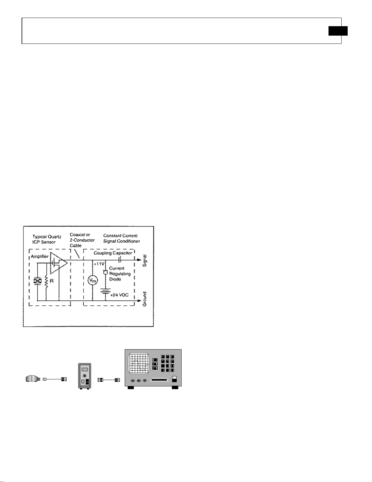
Power to operate ICP sensors is generally in the form of a low
cost, 24-27 VDC, 2-20 mA constant current supply. Figure
1.1 schematically illustrates a typical ICP strain sensor system.
PCB offers a number of AC or battery-powered, single or
multi-channel power/signal conditioners, with or without gain
capabilities for use with strain sensors. In addition, many data
acquisition systems now incorporate constant current power
for directly powering ICP sensors. Because static calibration
or quasi-static short-term response lasting up to a few seconds
is often required, PCB manufactures signal conditioners that
provide DC coupling. Figure 1.2 summarizes a complete 2-
wire ICP system configuration.
Figure 1.1 ICP®Sensor System Schematic
Readout Device
(not supplied)
Output
Cable
ICP®Sensor
Signal
Conditioner
Standard
Sensor Cable
ICP®Strain
Sensor
Figure 1.2 Typical ICP®Sensor System
In addition to ease of operation, ICP quartz strain sensors offer
significant advantages over charge mode types. Because of the
low impedance output and solid-state, hermetic construction,
ICP quartz strain sensors are well suited for continuous,
unattended strain monitoring in harsh factory environments.
Also, ICP sensor cost-per-channel is substantially lower, since
they operate through standard, low-cost coaxial cable, and do
not require expensive charge amplifiers.
Refer to the installation/outline drawing and specification
sheet at the front of this manual for details and dimensions of
the particular sensor model number(s) purchased. The
following pages give a brief description of the sensor series,
recommended mounting procedures, operation and
recommended calibration.
In addition to standard products, PCB has the ability to design
and manufacture custom sensors/systems for specific
applications.
If questions arise regarding the operation or characteristics of
the strain sensor products as outlined in this manual, feel free
to contact an experienced applications engineer from the
Force/Torque Division of PCB toll-free 888-684-0004.
2.0 DESCRIPTION
240 series quartz strain sensors are used to monitor the
dynamic response of crimping, stamping, punching, forming
and any other applications where it is crucial to maintain
process control. These sensors are ideal in applications where
mounting directly in the load path with a force sensor is not
possible. Instead, the sensor can be mounted in an area that
will provide the highest mechanical stress for the process to be
monitored. Strain sensors are mounted to a structure by means
of a supplied socket flat head screw, which threads into a
corresponding tapped hole, and is then fastened securely as
noted in the installation section of this manual. When used
with a constant current signal conditioner, the sensor output
voltage can be resolved in units of strain and then related to
specific events that must be monitored in the process. After
defining a signature voltage response for properly
manufactured parts, the user can then determine an acceptable
upper and lower control limit in order to maintain process
control thereby preventing the acceptance of non-conforming
products as finished goods.
Versions offering full-scale measurements of 10 to 300
are available. When powered by a constant current power
supply and subjected to an input strain, an ICP strain sensor
will provide a corresponding output voltage. A positive output
voltage indicates that the structure being monitored is being
subjected to a tensile force in the sensor mounting area and
can also be resolved in units of strain. Likewise, a compressive
force in this area will result in a negative output voltage. Refer
to Sections 3.1, for recommended strain sensor mounting and
torque requirements.

ICPQUARTZ STRAIN SENSOR OPERATION MANUAL
2
3.0 INSTALLATION
Refer to the Installation Drawing supplied with this manual for
specific outline dimensions and installation details for your
particular model. The specification is also included to provide
details of the sensor’s characteristic properties.
It is important that the mounting surface is clean and free of
paint, oil, or other coatings that could prevent the proper
transfer of strain into the mounting pads of the sensor. Poor
surface contact may affect sensor sensitivity and result in
erroneous data. Prior to mounting, it is recommended that the
machine surface and the mounting pads of the sensor be
cleaned with acetone. This will maintain proper coupling with
these mating surfaces and prevent slippage at peak strain.
Connect one end of the coaxial cable to the sensor connector
and the other end to the XDCR jack on the signal conditioner.
Make sure to tighten the cable connector to the sensor. DO
NOT spin the sensor onto the cable, as this fatigues the cable’s
center pin, resulting in a shorted signal and a damaged cable.
If the cable cannot be attached prior to sensor installation, the
protective cap should remain on the connector to prevent
contamination or damage.
For installation in dirty, humid, or rugged environments, it is
suggested that the connection be shielded against dust or
moisture with shrink tubing or other protective material. Strain
relieving the cable/sensor connection can also prolong cable
life. Mounting cables to a test structure with tape, clamps,
or adhesives minimizes the chance of damage.
3.1 STRAIN SENSOR INSTALLATION
Figure 3.1 displays the sensor mounted using the supplied
mounting screw to a minimum torque of 10 N-m. Allow for
the static component of the signal to discharge prior to
calibration. Installations not preloaded to the recommended
value, or that utilizes a screw of different material and/or
dimensions than the supplied screw, may yield inaccurate
output readings. The supplied screw allows proper strain
transmission to the sensor while holding the sensor in place.
Properly machined holes for the mounting screw will ensure
proper vertical orientation of the sensor. Refer to the
installation drawing for additional mounting details.
Consult a PCB applications engineer for calibration and output
recommendations.
Figure 3.1 Strain Sensor Installation
CAUTION!
Please read all instructions before attempting to
operate this product.
Damage to built-in amplifier
due to incorrect power or misapplication is NOT
covered by warranty

ICPQUARTZ STRAIN SENSOR OPERATION MANUAL
3
4.0 OPERATION
4.1 TYPICAL ICP SYSTEM CONFIGURATION
Sensors with built-in ICP circuitry require a constant-current
excitation voltage for operation. The enclosed Specification
Sheet provides specific power requirements. Required supply
voltage is normally 20 to 30 VDC, while the constant current
required ranges from 2 to 20 mA.
PCB standard battery-powered signal conditioners are factory
set at 2 mA and may be used to adequately drive a signal for
100 feet. PCB line signal supplies are factory set at 4 mA (and
adjustable from 2 to 20 mA), enabling signals to be transmitted
over hundreds of feet.
It is necessary to supply the sensor with a 2 to 20 mA constant
current at +20 to +30 VDC through a current-regulating diode
or equivalent circuit, contained in all PCB signal conditioners.
See Guide G-0001B for powering and signal conditioning
information pertaining to all ICP®instrumentation.
Most of the signal conditioners manufactured by PCB have an
adjustable current feature allowing a choice of input currents
from 2 to 20 mA. In general, for lowest noise (best
resolution), choose the lower current ranges. When driving
long cables (to several thousand feet), use the higher current,
up to 20 mA maximum. Consult the factory to determine if
higher current settings are required. Connect the sensor to the
power unit as shown in the typical ICP®sensor systems below.
As displayed in Figure 4.1, operation requires the connection
of the strain sensor first to a signal conditioner, then to a
readout device (oscilloscope, meter, recorder, or A-to-D
board) or to a readout device with built-in ICP sensor
excitation. Tighten the coaxial cable to the sensor by hand to
ensure good electrical contact.
Readout Device with
Built-in ICP®
Sensor Excitation
(not supplied)
Standard
Sensor Cable or
Output Cable
ICP
®Strain
Sensor
Readout Device
(not supplied)
Output
Cable
ICP®Sensor
Signal
Conditioner
Standard
Sensor Cable
ICP®Strain
Sensor
Figure 4.1 Typical ICPSystem Configurations

ICPQUARTZ STRAIN SENSOR OPERATION MANUAL
4
5.0 POLARITY
Extension of the mounting area of an ICP strain sensor
produces a positive-going voltage output. The retraction of the
mounting area produces a negative-going voltage output.
6.0 LOW-FREQUENCY MONITORING
Strain sensors used for applications in short term, steady-state
monitoring, such as sensor calibration, or short term, quasi-
static testing should be powered by signal conditioners that
operate in DC-coupled mode. PCB Series 484 Signal
Conditioner operates in either AC or DC-coupled mode and
may be supplied with gain features or a zero “clamped”output
often necessary in repetitive, positive polarity pulse train
applications.
If you wish to learn more about ICP sensors, consult PCB’s
General Signal Conditioning Guide, a brochure outlining the
technical specifics associated with piezoelectric sensors. This
brochure is available from PCB by request, free of charge.
7.0 DISCHARGE TIME CONSTANT
The discharge time constant (DTC) of the entire transduction
system from sensor to readout must be considered when
attempting to calibrate an ICP strain sensor by static methods.
In order to take full advantage of the long DTC built into the
strain sensor, it is best to DC couple from the sensor to the
readout device. Several dual-mode PCB signal conditioners
(e.g., Series 484) use direct coupling techniques to decouple
the output signal from the sensor bias voltage. With the output
of the signal conditioner coupled to a DC readout, such as a
digital voltmeter (DVM) or oscilloscope, the time constant of
the sensor is not compromised by AC coupling elsewhere in
the system.
When DC coupling to a system, it is important to DC couple
the entire system and not just from the sensor to the signal
conditioner. The system time constant is determined by the
shortest time constant in the system. For this reason, the signal
conditioner, as well as the readout device, must be DC
coupled.
Figure 7.1 Characteristic Discharge Time Constant Curve
The discharge time constant represents the decay rate of an
input signal. One DTC represents the amount of time taken for
the signal to decay to 37% of the initial peak value. As
illustrated in Figure 7.1, this is an exponential decay.
Approximately five DTC intervals are needed for a peak signal
to naturally decay back to zero.
The rule of thumb for signal discharge, as outlined in Figure
7.2, is this: for the first 10% of the DTC, the signal lost is
approximately proportional to the time elapsed.
Figure 7.2 Step Function Response
For example, a sensor with a 150-second DTC loses
approximately 1% of its output level the first 1.5 seconds (1%
of 150) after the application of a steady state strain within the
measuring range. In this case, the output reading must be taken
within 1.5 seconds of the strain application for 1% accuracy.
If it is impossible to avoid AC coupling somewhere in the
sensing system, try to keep the coupling DTC at least an order
of magnitude longer than the DTC of the strain sensor. This
avoids compromising the sensor DTC.
8.0 CALIBRATION
Strain sensors are calibrated relative to a strain gage reference
sensor. A calibration certificate is supplied with each strain
sensor providing its relative voltage sensitivity (mV/). A
calibration must be performed once strain sensors are installed
in the specific equipment being measured. This is necessary so
that a direct comparison of relative data can be made thereby
allowing the user to set control limits and properly monitor a
specific event as well as the entire process.

ICPQUARTZ STRAIN SENSOR OPERATION MANUAL
5
9.0 TROUBLESHOOTING
When a PCB signal conditioner with any of the following
indicators are used, turn the power on and observe the
voltmeter (or LED’s) on the front panel. Typical indicators are
marked as shown in the figure below.
Normal Operation
INDICATOR DVM
READING OPERATION
GREEN (Mid-
Scale) 8 to 14 V Proper range for most ICP
sensors.
GREEN
(Low End) 3 to 7 V Proper range for low bias
ICP sensors.
GREEN
(High End) 15 to 17 V Proper range for high bias
ICP sensors.
RED 0 Volts Short in the sensor, cable, or
connections.
YELLOW 24 to 28 V Open circuit in the sensor,
cable, or connections.
(Excitation voltage is being
monitored.)
Output voltage moves from YELLOW to GREEN slowly until
charging is complete. AC coupled signal conditioners require
sufficient time to charge the internal coupling capacitor. Allow
signal conditioner to charge for after 5 discharge time
constants for stable operation.
Note: Most PCB strain sensors have an output bias of 8-14
VDC. Refer to the specification sheet in this manual for the
bias range of the model you are using. If you are using a low
bias sensor, the indicator will be at the bottom end of the green
portion of the dial indicator, and may even be in the red
portion. This is the expected range and indicates proper
operation. Initial application of mounting torque will incur a
negative-going output voltage. It is necessary to allow this
output voltage to decay 5 DTC’s prior to making
measurements in order to prevent baseline shift where an
absolute zero is needed throughout entire monitoring process.
10.0 MAINTENANCE
The sensor connector must be kept clean, especially if it is
operating in a dusty and/or wet environment. If the cable is
disconnected from the sensor, it is recommended to place the
supplied black cap onto the connector to prevent
contamination.
Observe the following precautions when using the sensor:
A. Do not exceed the maximum strain levels for the strain
sensor (see specification sheet).
B. Do not subject the sensor to temperatures exceeding that of
the specification, normally 250°F (121°C).
C. Do not apply voltage to the sensor without current-limiting
diodes or other current protection.
D. Do not apply more than 20 mA of current to the strain
sensor.
E. When mounting the strain sensor, observe installation
procedures detailed in Section 3.0 and as outlined on the
specific sensor Installation Drawing to avoid over torquing
when mounting.
F. Do not apply more than 30 volts to the sensor.
G. Avoid metal-to-metal impacts during applications, which
can produce a high frequency ringing. Electrical low-pass
filtering or a damping material can help reduce such effects.
E. Do not spin the sensor onto the cable. This may fatigue the
cable center pin, causing cable damage. Always insert the
cable pin into the sensor and tighten the knurled cable nut to
the sensor.
For additional information, refer to “Warranty, Service,
Repair and Return Policies and Instructions.”
MANUAL NUMBER: 22676
MANUAL REVISION: A
ECN NUMBER: 17580

Model Number
RHM240A02 UNIAXIAL STRAIN SENSOR Revision: A
ECN #: 45631
Performance ENGLISH SI
Sensitivity(± 20 %) 50 mV/µε50 mV/µε
Measurement Range 100 pk µε100 pk µε[2]
Frequency Range(-5 %) 0.004 Hz 0.004 Hz [3]
Broadband Resolution(1 to 10,000 Hz) 0.0002 µε0.0002 µε[1]
Non-Linearity ≤2 % ≤2 % [4]
Environmental
Temperature Range(Operating) -65 to +250 °F -54 to +121 °C [1]
Electrical
Excitation Voltage 20 to 30 VDC 20 to 30 VDC
Constant Current Excitation 2 to 20 mA 2 to 20 mA
Output Bias Voltage 8 to 14 VDC 8 to 14 VDC
Discharge Time Constant ≥150 sec ≥150 sec
Physical
Sensing Element Quartz Quartz
Housing Material Stainless Steel Stainless Steel
Electrical Connector 10-32 Coaxial Jack 10-32 Coaxial Jack
Electrical Connection Position Side Side
Sealing Epoxy Epoxy
Mounting Torque 7.38 ft-lb 10 Nm
Size (Width x Length x Height) 0.67 in x 1.81 in x 0.6 in 17 mm x 46 mm x 15.2 mm
Weight 1.6 oz 45 gm [1]
All specifications are at room temperature unless otherwise specified.
In the interest of constant product improvement, we reserve the right to change specifications without notice.
ICP®is a registered trademark of PCB Group, Inc.
W- Water Resistant Cable
NOTES:
[1]Typical.
[2]Based on 10 mV/μє sensitivity.
[3]Calculated from discharge time constant.
[4]Zero-based, least-squares, straight line method.
[5]See PCB Declaration of Conformance PS023 for details.
SUPPLIED ACCESSORIES:
Model M081A100 M6 x 1.00 flathead screw (1)
3425 Walden Avenue, Depew, NY 14043
Phone: 716-684-0001
Fax: 716-684-0987
E-Mail: [email protected]
[5]
OPTIONAL VERSIONS
Optional versions have identical specifications and accessories as listed for the standard model
except where noted below. More than one option may be used.
Entered: LK Engineer: APB Sales: WDC Approved: APB Spec Number:
Date: 7/8/2016 Date: 7/8/2016 Date: 7/8/2016 Date: 7/8/2016 36796

1
1
2
2
A A
B B
CODE
IDENT. NO.
52681
DWG. NO.
SCALE: SHEET
DRAWN CHECKED ENGINEER
TITLE
UNLESS OTHERWISE SPECIFIED TOLERANCES ARE:
DIMENSIONS IN MILLIMETERS
[ IN BRACKETS ]
XX ± 0.13
ANGLES 2 DEGREES
3425 WALDEN AVE. DEPEW, NY 14043
(716) 684-0001 E-MAIL: sales@pcb.com
DIMENSIONS IN INCHES
DECIMALS XX ±.01
ANGLES 2 DEGREES
FILLETS AND RADII
.003 - .005
DECIMALS X ± 0.3
FILLETS AND RADII
0.07 - 0.13
INSTALLATION DRAWING
22493
1 OF 1
1.5X
MODEL 240XXX SERIES
STRAIN SENSOR
XXX ±.005
NJF 10/01/19 MCK 09/27/17 MJK 09/27/17
22493
PCB Piezotronics Inc. claims proprietary rights in
the information disclosed hereon. Neither it nor any
reproduction thereof will be disclosed to others
without the written consent of PCB Piezotronics Inc.
REVISIONS
REV DESCRIPTION DIN
E UPDATED DIMENSIONS 49953
MOUNTING SURFACE MUST BE FLAT TO WITHIN
.001 [.03] WITH AT LEAST A SURFACE FINISH OF 125 [3.2]
1
2
3TORQUE SCREW TO 86 IN-LBS [10 Nm] MINIMUM
DRILL PERPENDICULAR TO MOUNTING SURFACE WITHIN 1°
MOUNTING HOLE PREPARATION:
.199 [5.05] .45 [11.4]
M6x1.00-6H .35 [8.9] 1
2
1.15 [29.2]
.60 [15.2]2X
1.58 [40.0]
.18 [4.6]
.24 [6.0]
10-32 UNF - 2A
ELECTRICAL CONNECTOR
.67 [17.0]
MODEL M081A100:
M6x1.00-6g X .87 [22.0] LONG
FLAT HEAD HEX SCREW
3
Table of contents
Other PCB Piezotronics Sensor manuals