PCB 1102-04A User manual

Model 1102-04A
Strain Gage Load Cell
Installation and Operating Manual
For assistance with the operation of this product,contact:
PCB Load & Torque, Inc.
Toll-free: 866-684-7107
24-hour SensorLine™: 716-684-0001
Fax: 248-888-8266
Web: www.pcbLoadTorque.com

The information contained in this document supersedes all similar information that
may be found elsewhere in this manual.
Total Customer Satisfaction –PCB
Piezotronics guarantees Total Customer
Satisfaction. If, at any time, for any
reason, you are not completely satisfied
with any PCB product, PCB will repair,
replace, or exchange it at no charge.
You may also choose to have your
purchase price refunded in lieu of the
repair, replacement, or exchange of the
product.
Service –Due to the sophisticated
nature of the sensors and associated
instrumentation provided by PCB
Piezotronics, user servicing or repair is
not recommended and, if attempted,
may void the factory warranty. Routine
maintenance, such as the cleaning of
electrical connectors, housings, and
mounting surfaces with solutions and
techniques that will not harm the
physical material of construction, is
acceptable. Caution should be observed
to insure that liquids are not permitted to
migrate into devices that are not
hermetically sealed. Such devices
should only be wiped with a dampened
cloth and never submerged or have
liquids poured upon them.
Repair –In the event that equipment
becomes damaged or ceases to
operate, arrangements should be made
to return the equipment to PCB
Piezotronics for repair. User servicing or
repair is not recommended and, if
attempted, may void the factory
warranty.
Calibration –Routine calibration of
sensors and associated instrumentation
is recommended as this helps build
confidence in measurement accuracy
and acquired data. Equipment
calibration cycles are typically
established by the users own quality
regimen. When in doubt about a
calibration cycle, a good “rule of thumb”
is to recalibrate on an annual basis. It is
also good practice to recalibrate after
exposure to any severe temperature
extreme, shock, load, or other
environmental influence, or prior to any
critical test.
PCB Piezotronics maintains an ISO-
9001 certified metrology laboratory and
offers calibration services, which are
accredited by A2LA to ISO/IEC 17025,
with full traceability to SI through
N.I.S.T. In addition to the normally
supplied calibration, special testing is
also available, such as: sensitivity at
elevated or cryogenic temperatures,
phase response, extended high or low
frequency response, extended range,
leak testing, hydrostatic pressure
testing, and others. For information on
standard recalibration services or
special testing, contact your local PCB
Piezotronics distributor, sales
representative, or factory customer
service representative.
Returning Equipment –Following
these procedures will insure that your
returned materials are handled in the
most expedient manner. Before
Warranty, Service, Repair, and
Return Policies and Instructions

returning any equipment to PCB
Piezotronics, contact your local
distributor, sales representative, or
factory customer service representative
to obtain a Return Warranty, Service,
Repair, and Return Policies and
Instructions Materials Authorization
(RMA) Number. This RMA number
should be clearly marked on the outside
of all package(s) and on the packing
list(s) accompanying the shipment. A
detailed account of the nature of the
problem(s) being experienced with the
equipment should also be included
inside the package(s) containing any
returned materials.
A Purchase Order, included with the
returned materials, will expedite the
turn-around of serviced equipment. It is
recommended to include authorization
on the Purchase Order for PCB to
proceed with any repairs, as long as
they do not exceed 50% of the
replacement cost of the returned
item(s). PCB will provide a price
quotation or replacement
recommendation for any item whose
repair costs would exceed 50% of
replacement cost, or any item that is not
economically feasible to repair. For
routine calibration services, the
Purchase Order should include
authorization to proceed and return at
current pricing, which can be obtained
from a factory customer service
representative.
Warranty –All equipment and repair
services provided by PCB Piezotronics,
Inc. are covered by a limited warranty
against defective material and
workmanship for a period of one year
from date of original purchase. Contact
PCB for a complete statement of our
warranty. Expendable items, such as
batteries and mounting hardware, are
not covered by warranty. Mechanical
damage to equipment due to improper
use is not covered by warranty.
Electronic circuitry failure caused by the
introduction of unregulated or improper
excitation power or electrostatic
discharge is not covered by warranty.
Contact Information –International
customers should direct all inquiries to
their local distributor or sales office. A
complete list of distributors and offices
can be found at www.pcb.com.
Customers within the United States may
contact their local sales representative
or a factory customer service
representative. A complete list of sales
representatives can be found at
www.pcb.com. Toll-free telephone
numbers for a factory customer service
representative, in the division
responsible for this product, can be
found on the title page at the front of this
manual. Our ship to address and
general contact numbers are:
PCB Piezotronics, Inc.
3425 Walden Ave.
Depew, NY14043 USA
Toll-free: (800) 828-8840
24-hour SensorLineSM: (716) 684-0001
Website: www.pcb.com

PCB工业监视和测量设备 - 中国RoHS2公布表
PCB Industrial Monitoring and Measuring Equipment - China RoHS 2 Disclosure Table
部件名称
有害物质
铅(Pb)
汞
(Hg)
镉
(Cd)
六价铬(Cr(VI))
多溴联苯 (PBB)
多溴二苯醚(PBDE)
住房
O
O
O
O
O
O
PCB板
X
O
O
O
O
O
电气连接器
O
O
O
O
O
O
压电晶体
X
O
O
O
O
O
环氧
O
O
O
O
O
O
铁氟龙
O
O
O
O
O
O
电子
O
O
O
O
O
O
厚膜基板
O
O
X
O
O
O
电线
O
O
O
O
O
O
电缆
X
O
O
O
O
O
塑料
O
O
O
O
O
O
焊接
X
O
O
O
O
O
铜合金/黄铜
X
O
O
O
O
O
本表格依据 SJ/T 11364 的规定编制。
O:表示该有害物质在该部件所有均质材料中的含量均在 GB/T 26572 规定的限量要求以下。
X:表示该有害物质至少在该部件的某一均质材料中的含量超出 GB/T 26572 规定的限量要求。
铅是欧洲RoHS指令2011/65/ EU附件三和附件四目前由于允许的豁免。
CHINA RoHS COMPLIANCE

DOCUMENT NUMBER: 21354
DOCUMENT REVISION: C
ECN: 45605
Component Name
Hazardous Substances
Lead
(Pb)
Mercury
(Hg)
Cadmium
(Cd)
Chromium VI
Compounds
(Cr(VI))
Polybrominated
Biphenyls
(PBB)
Polybrominated
Diphenyl
Ethers (PBDE)
Housing
O
O
O
O
O
O
PCB Board
X
O
O
O
O
O
Electrical
Connectors
O
O
O
O
O
O
Piezoelectric
Crystals
X
O
O
O
O
O
Epoxy
O
O
O
O
O
O
Teflon
O
O
O
O
O
O
Electronics
O
O
O
O
O
O
Thick Film
Substrate
O
O
X
O
O
O
Wires
O
O
O
O
O
O
Cables
X
O
O
O
O
O
Plastic
O
O
O
O
O
O
Solder
X
O
O
O
O
O
Copper Alloy/Brass
X
O
O
O
O
O
This table is prepared in accordance with the provisions of SJ/T 11364.
O: Indicates that said hazardous substance contained in all of the homogeneous materials for this part is below the limit
requirement of GB/T 26572.
X: Indicates that said hazardous substance contained in at least one of the homogeneous materials for this part is above
the limit requirement of GB/T 26572.
Lead is present due to allowed exemption in Annex III or Annex IV of the European RoHS Directive 2011/65/EU.

PCB Load & Torque Toll-Free in USA 866-684-7107 716-684-0001 www.pcb.com
CANISTER LOAD CELL OPERATION MANUAL
1
TABLE OF CONTENTS
1.0 INTRODUCTION..................................................................................................................2
2.0 SAFETY PRECAUTIONS....................................................................................................2
3.0 OVERVIEW..........................................................................................................................2
3.1 Dimensions .......................................................................................................................................2
3.2 Optional Components .......................................................................................................................2
4.0 MECHANICAL INSTALLATION..........................................................................................2
5.0 ELECTRICAL INSTALLATION ...........................................................................................3
5.1 Electrical Drawing / Western Regional Std.......................................................................................3
5.2 Output Polarity ..................................................................................................................................3
5.3 Cable & Grounding Considerations ..................................................................................................3
6.0 CALIBRATION.....................................................................................................................3
6.1 Calibration Certificate Description.....................................................................................................3
6.1.1 Measured Output.....................................................................................................................4
6.1.2 Hysteresis................................................................................................................................4
6.1.3 Best Fit Output........................................................................................................................4
6.1.4 Strain Gage Measurements .....................................................................................................4
6.1.5 Shunt Calibration Standard Resistor.......................................................................................4
6.1.6 Static Error Band (SEB)..........................................................................................................4
7.0 SHUNT CALIBRATION DESCRIPTION..............................................................................4
7.1 Resistor Value...................................................................................................................................4
7.2 Shunt Calibration Process.................................................................................................................4
7.3 Estimating Shunt Resistor for a Given Load.....................................................................................4
8.0 MAINTENANCE...................................................................................................................5
9.0 TROUBLESHOOTING.........................................................................................................5
9.1 Mechanical Troubleshooting.............................................................................................................5
9.2 Electrical Troubleshooting.................................................................................................................5
10.0 CALIBRATION / REPAIR SERVICES...............................................................................5
10.1 RMA / Purchase Order....................................................................................................................5
11.0 WARRANTY ......................................................................................................................5
PCB Load & Torque Toll-Free in USA 866-684-7107 716-684-0001 www.pcb.com
CANISTER LOAD CELL OPERATION MANUAL
2
1.0 INTRODUCTION
General purpose canister load cells manufactured by PCB
Load & Torque are suitable for a wide range of general force
measurement applications, including weighing, dynamometer
use, and static material test machines. These load cells
operate in tension and compression. Standard 1/4”-28 female
threads facilitate ease of installation.
The following document explains the characteristics and
installation of the canister load cells.
2.0 SAFETY PRECAUTIONS
Failure of the load cell structure may cause personal injury
and equipment damage.
The load cell can withstand loads of at least 150% of the full-
scale capacity before any damage occurs to the sensing
element. Be sure that the load cell and any fixturing used is
properly designed, fabricated, and securely installed prior to
use.
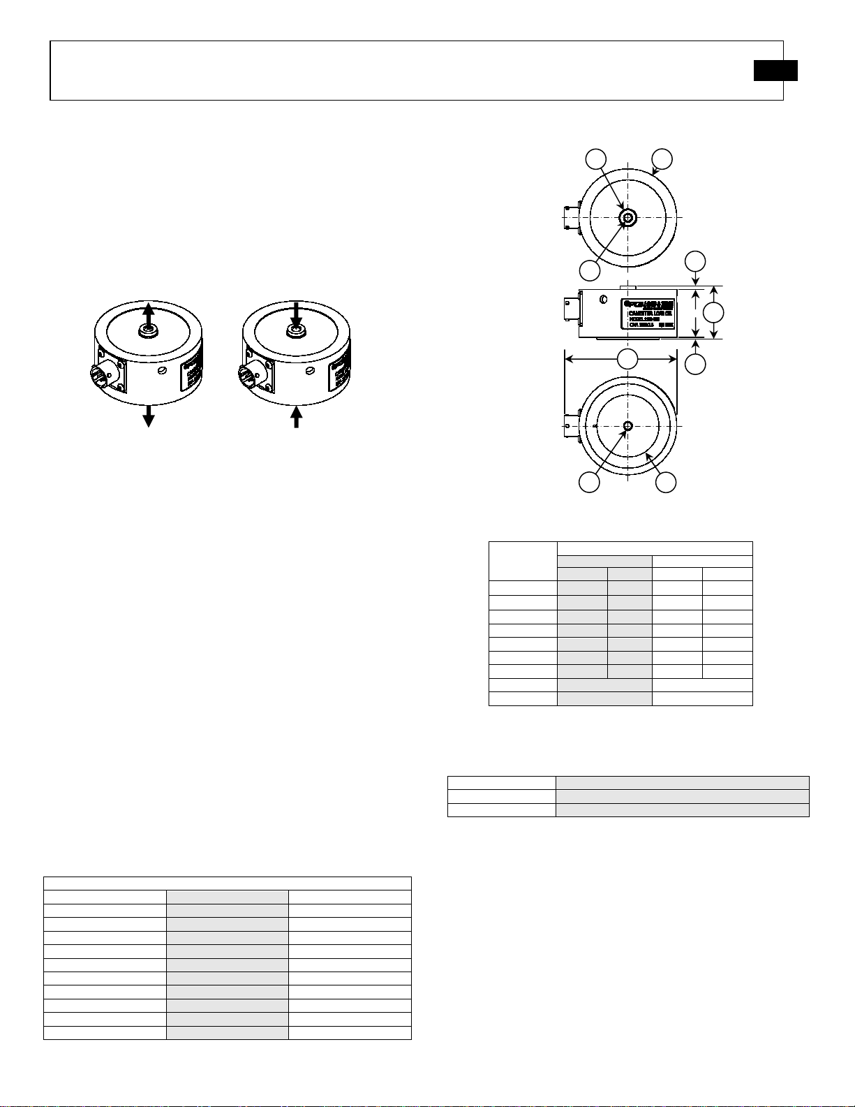
3.0 OVERVIEW
Canister load cells come in a variety of capacities to handle
loads ranging from 25 lbf to 300 lbf.
3.1 Dimensions
3.2 Optional Components
4.0 MECHANICAL INSTALLATION
Loads applied to canister load cells must be even and centered.
Compensation linkages (e.g. rod end bearing, alignment
couplers) are recommended to help minimize load
misalignment. When installing fixtures, be sure to thread the
fixture to the load cell, and not the load cell to the fixture. If
alignment fixtures are not used, ensure loading surfaces are
flat and parallel, with loads applied in-line with the sensor.
Figure 2 - Dimensions
Table 2 - Dimension Values
Table 1 - Full-Scale Capacities
Figure 1 – Canister Load Cell Loading
Full
-
Scale Capacities
Model
(lbf)
(N)
1102
-
05A
25 110
1102
-
01A
50 222
1102
-
02A
100 445
1102
-
03A
200 900
1102
-
04A
300 1334
M1102
-
05A
28 125
M1102
-
01A
56 250
M1102
-
02A
112 500
M1102
-
03A
225 1000
M1102
-
04A
337 1500
Dimensions
(see Figure 2)
Series Number
1102 M1102
(in) (mm) (in) (mm)
1
∅
2.75
∅
69.9
∅
2.75
∅
69.9
2
∅
0.44
∅
11.2
∅
0.44
∅
11.2
3
∅
1.75
∅
44.5
∅
1.75
∅
44.5
4
1.50 38.1 1.50 38.1
5
0.09 2.3 0.09 2.3
6
0.06 1.5 0.06 1.5
7
3.17
80.5
3.17
80.5
8
¼”-28 Tapped M6x1.0 Tapped
9
¼”-28 Tapped M6x1.0 Tapped
4
5
7
9 3
2 1
8
6
Tensile Load
Tensile Load
Compression
Load
Compression Load
Item Number
Descript
ion
181-012A PT06A-10-6S (SR), Mating Connector
8311-01-10A Cable – Non-Coax, PT65 to Pigtail, 10 feet
Table 3 - Optional Components

PCB Load & Torque Toll-Free in USA 866-684-7107 716-684-0001 www.pcb.com
CANISTER LOAD CELL OPERATION MANUAL
3
5.0 ELECTRICAL INSTALLATION
5.1 Electrical Drawing / Western Regional Std.
All load cells are wired following the Western Region
Standard. All models utilize strain gages configured into a
Wheatstone Bridge Circuit to produce the primary sensing
element. The four-arm Wheatstone bridge configuration is
shown below in Figure 3.
The gages are bonded to the load cell's structure.
Typically, a regulated DC or AC excitation is applied
between A and D of the bridge. When a force is applied to
the load cell, the Wheatstone bridge becomes unbalanced,
causing an output voltage between B and C, which is
proportional to the applied load. This configuration allows
for temperature and pressure compensation, as well as
cancellation of signals caused by forces not directly
applied to the axis of the applied load. Output is typically
expressed in units of mV/V of excitation.
5.2 Output Polarity
The following figure describes the output polarity.
5.3 Cable & Grounding Considerations
Proper grounding and shielding is required to prevent
electrical noise in strain gage load cell measuring systems.
The cable must be shielded twisted pairs with a drain wire.
Cable shields must be grounded only at one end, for example,
on the instrument or control system ground. The load cell
case is grounded by mechanical attachment to the structure to
which it is mounted.
The instrument or control system is grounded through its
power cord. Ground loops and measuring system wiring may
result in unstable or noisy signals.
A simple test with a voltmeter connected between the power
cord ground and the structure on which the load cell is
mounted can confirm that the structure has been properly
grounded. If the power cord ground and structure ground are
not at the same potential, it may be necessary to provide a
secure structure ground, perhaps by driving a copper rod and
attaching a ground strap.
6.0 CALIBRATION
Every canister load cell manufactured by PCB Load & Torque
has been fully calibrated per ISO/IEC 17025 procedures, and
meets all published specifications. Each load cell will come
with a calibration certificate designated with matching model
and serial numbers. PCB Load & Torque also offers
calibration services on an on-going basis.
6.1 Calibration Certificate Description
Calibration reports supplied with canister load cells contain
valuable information to assist the customer in use of the
equipment. A separate calibration report is provided for
tension and compression calibrations. Calibration procedures,
equipment, and reports comply with ISO/IEC 17025.
Table 4 - Electrical Connections
Figure 5 - Grounding
Test Rig Ground
Power Supply
Instrument Ground
Cable Shielding
Load Cell
C
A
D
B
- Signal White
- Excitation Black
+ Excitation Red
+ Signal Green
Figure 3 - Western Regional Strain Gage Committee Wiring Code
Figure 4 - Output Polarity
Load Cell Receptacle: PT02E-10-6P
Mating Connector: PT02A-10-6S
PCB Load & Torque P/N: 181-012A
Tensile Load
= Positive
Tensile Load
= Positive
Compression Load
= Negative
Compress
ion Load
= Negative
PCB Load & Torque Toll-Free in USA 866-684-7107 716-684-0001 www.pcb.com
CANISTER LOAD CELL OPERATION MANUAL
4
6.1.1 Measured Output
The applied load starting at zero is measured in five
increments to full scale. Output (mV/V) is measured at each
increment. The straight-line from zero to the full scale
measurement is compared to the measured readings at each
increment to calculate the error at each load increment. The
deviations (% Full Scale) corresponding to non-linearity at
each measurement increment are then calculated.
6.1.2 Hysteresis
The difference between the ascending and descending
measured readings at 40% of full scale is used to calculate the
hysteresis value.
6.1.3 Best Fit Output
The best fit calibration second-order equation has been
calculated from the calibration data by the method of least
squares. Deviation between measured output and best-fit
output is calculated and displayed in the column next to the
best-fit output for each measurement increment. The
deviations (% Full Scale) of measured outputs from the
calculated best fit are tabulated for each measured reading.
6.1.4 Strain Gage Measurements
6.1.5 Shunt Calibration Standard Resistor
All canister load cell calibrations use a 120K Ohm (0.1%)
precision resistor shunt calibration value that is supplied into
the calibration report.
6.1.6 Static Error Band (SEB)
The static error band (SEB) is determined by the maximum
deviations of the ascending and descending calibration points
from the best fit straight line through zero output. The SEB
includes the effects of nonlinearity, hysteresis, and non-return
to minimum load.
7.0 SHUNT CALIBRATION DESCRIPTION
Shunt calibration is used to simulate a known tension or
compression load on a load cell. The calibration certificate
will indicate which leg of the bridge to apply the shunt resistor
to for both tension and compression load simulation. Typically
tension is simulated by inserting the shunt resistor between the
+P and +S connector leads. Compression loading is simulated
by inserting the shunt resistor between the +S and –P
connector leads.
7.1 Resistor Value
Canister load cells have a nominal 2.0 mV/V full scale output.
For a 700 ohm strain gage bridge the precision shunt resistor,
120,000 ohms ±0.1%, simulates an output of approximately
73% of the full scale output for the load cell. The calibration
values for each bridge are found on the calibration certificates
supplied with each load cell.
7.2 Shunt Calibration Process
To perform the shunt calibration, use the following procedure:
1. Stabilize all forces on the load cell. If possible,
remove all loads.
2. Power up the host signal conditioner and connect it to
the load cell via appropriate cable, and allow for a 30
minute warm up.
3. Set the load indicator display to read exactly 00.000.
4. Connect the shunt resistor to the terminals specified
in the calibration certificate, and adjust the span or
gain until the display reads the force value stated on
the certificate.
5. Repeat steps 1-3 to verify that a valid calibration
setting has been obtained.
6. If possible, apply a known load to the measurement
system to further verify that the calibration has been
accurately set up.
7.3 Estimating Shunt Resistor for a Given Load
The following formula can be used to estimate the
approximate value of shunt resistor required to simulate a
mechanical load.
R
cal
= (25 * R
b
) / (Output
FS
* L
cal
)
Where: R
cal
= Shunt Resistor (K ohms)
R
b
= Bridge Resistance (ohms)
Output
FS
= Full Scale output of the load cell (mV/V)
L
cal
= Load to be simulated, % of Load Cell Capacity
Bridge Resistance: 700 Ohm Nominal
Excitation: +P(A) to –P(D) Ohms
Signals: +S(B) to –S(C) Ohms
Leakage to Ground: > 5k GOhm
Bridge Unbalance: ±1.0% Full Scale
Output: 2.0 mV/V Nominal
Maximum Voltage: 20 VDC
Table 5 – Strain Gage Measurements

PCB Load & Torque Toll-Free in USA 866-684-7107 716-684-0001 www.pcb.com
CANISTER LOAD CELL OPERATION MANUAL
5
8.0 MAINTENANCE
Routine maintenance of the canister style load cell should
include cleaning the electrical connectors, housings, and
mounting surfaces with solutions and techniques that will not
harm the physical material of construction. Make sure liquids
are not allowed to migrate into devices that are not
hermetically sealed. Such devices should only be wiped with
a damp cloth, and never be submerged or have liquids poured
on them. Never use a pressure washer on the load cells.
Yearly calibrations are recommended to ensure that the unit’s
outputs match the factory specifications.
9.0 TROUBLESHOOTING
Proper performance of a load cell requires careful attention to
both electrical and mechanical aspects of the measurement
system. A basic understanding of the electrical and
mechanical installation requirements is recommended.
9.1 Mechanical Troubleshooting
A mechanical checklist includes:
1. Check for proper installation of fixturing.
2. Check integrity of the fixturing.
9.2 Electrical Troubleshooting
An electrical checklist should start with:
1. Check cables for proper wiring and make sure
connections are secure and proper.
2. Inspect for loose or dirty electrical connections.
3. Check for improper shield grounds.
4. Check for proper grounding of the structure that the
load cell is mounted on.
5. Check the signal conditioning electronics for proper
setup.
6. Check the insulation resistance of shielded
conductors for short circuits.
7. Check isolation resistance, load cell flexure to
conductors.
8. Check load cell bridge resistances, (A-D) excitation
and (B-C) the signal leads.
9. Check bridge balance.
10. Keep a record of your observations, correct problems,
or contact PCB factory for assistance.
10.0 CALIBRATION / REPAIR SERVICES
PCB Load & Torque offers calibration and repair services.
The PCB Calibration Laboratory in Farmington Hills,
Michigan is A2LA Accredited per ISO/IEC 17025.
Standard calibration certificates list five force points
ascending and one point descending. Additional data points
are available at extra cost upon request. A 60 K ohm (±0.1%)
shunt calibration resistor is supplied with each load cell
calibration.
Certificate information includes tabulated measurement
variable data zero balance, bridge input/output resistance,
computer nonlinearity and hysteresis, static error band (SEB)
calculations and entries abilities and traceability statements.
If an initial evaluation shows that a transducer requires repair,
PCB will provide the customer with an estimate prior to taking
any corrective action.
10.1 RMA / Purchase Order
Please request a return material authorization (RMA) before
sending a load cell back to the factory for any reason. For
calibration services, if possible, a copy of the purchase order
covering the requested services should be included with the
returned load cell.
11.0 WARRANTY
Standard warranty on canister style load cells covers parts and
workmanship. For full details, refer to the Warranty
Statement supplied with each load cell.
If the load cell is defective for reasons other than overloads,
return it to the factory for detailed evaluation. Factory
evaluation may show that the load cell is repairable or non-
repairable and if repair or replacement will be under warranty.
If not under warranty, acost of repairs and recalibration will
be provided. Once authorization to proceed is received, a
delivery date will be provided.
Manual Number: 56337
Manual Revision: A
Revision Date: 5/19/15
ECO Number: 44231

Model Number
1102-04A STRAIN GAGE LOAD CELL Revision: H
ECN #: 43815
Performance ENGLISH SI
Measurement Range 300 lb 1334 N [5
Sensitivity(± 10 %) 2 mV/V 2 mV/V [6
Non-Linearity ≤ 0.05 % FS ≤ 0.05 % FS
Hysteresis ≤ 0.05 % FS ≤ 0.05 % FS
Non-Repeatability ≤ 0.02 % FS ≤ 0.02 % FS
Eccentric Load Sensitivity ≤ .25 %/in ≤ .25 %/25.4mm
Resonant Frequency 7.0 kHz 7.0 kHz
Creep(in 20 minutes) ≤ .025 % ≤ .025 %
Static Error Band ≤ .05 % FS ≤ .05 % FS
Environmental
Overload Limit 450 lb 2000 N
Load Limit(Side Force, FX or FY) 300 lb 1334 N [3
Load Limit(Bending Moment, MX or MY) 300 in-lb 34 Nm [3
Load Limit(Axial Torque, MZ) 65 in-lb 7 Nm [3
Temperature Range(Operating) -65 to +200 °F -54 to +93 °C
Temperature Range(Compensated) +70 to +170 °F +21 to +77 °C
Temperature Effect on Output(Maximum) ± 0.0015 %Reading/°F ± 0.0027 %Reading/°C [4
Temperature Effect on Zero Balance(Maximum) ± 0.0008 %FS/°F ± 0.0015 %FS/°C [4
Electrical
Bridge Resistance 700 Ohm 700 Ohm [1
Excitation Voltage(Recommended) 10 VDC 10 VDC [2
Insulation Resistance >5x10⁹ Ohm >5x10⁹ Ohm
Zero Balance ≤ 1 % FS ≤ 1 % FS
Output Polarity +Tension +Tension
Physical
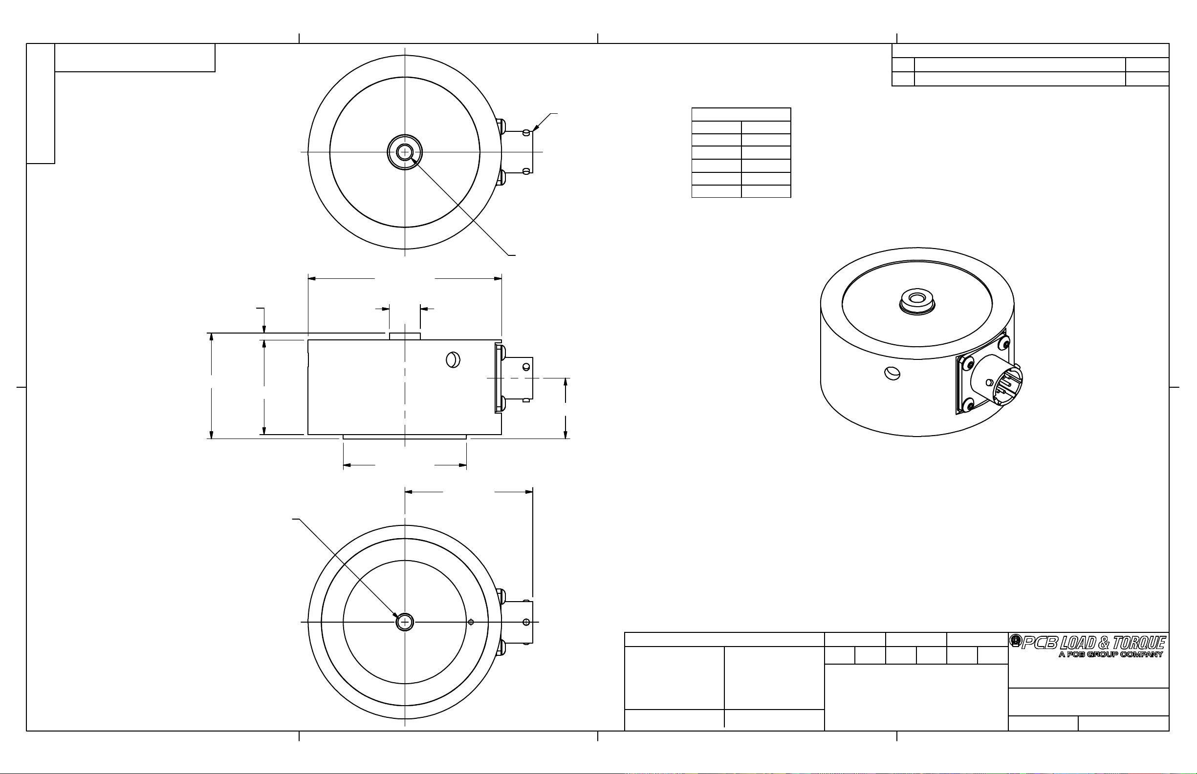
Size (Diameter x Height) 2.75 in x 1.5 in 69.9 mm x 38.1 mm [7
Weight 0.67 lb 304 g
Mounting Thread 1/4-28 Female No Metric Equivalent
Housing Material Painted Aluminum Painted Aluminum
Sensing Element Strain Gage Strain Gage
Deflection at Full Scale Capacity 0.003 in 0.08 mm
Electrical Connector PT02E-10-6P PT02E-10-6P
All specifications are at room temperature unless otherwise specified.
In the interest of constant product improvement, we reserve the right to change specifications without notice.
NOTES:
[1 Nominal.
[2 Calibrated at 10 VDC, usable 5 to 20 VDC or VAC RMS.
[3 Singularly applied, i.e. no other extraneous loads.
[4 Over compensated operating temperature range.
[5 FS - Full Scale.
[6 RO - Rated Output.
[7 See Outline Drawing 51277 for Complete Dimensions
OPTIONAL ACCESSORIES:
Model 181-012A PT06A-10-6S(SR)
Model 8311-01-10A CABLE
PCB Load & Torque, Inc.
24350 Indoplex Circle
armington Hills, MI 48335
UNITED STATES
Phone: 866-684-7107
ax: 716-684-0987
E-Mail: ltinfo@pcbloadtorque.com
Web site:
http://www.pcbloadtorque.com
OPTIONAL VERSIONS
Optional versions have identical specifications and accessories as listed for the standard
model except where noted below. More than one option may be used.
Entered: AP Engineer: PE Sales: JC Approved: JSD Spec Number:
Date: 2/17/2015 Date: 2/17/2015 Date: 2/17/2015 Date: 2/17/2015 18330
PIN A + EXC
PIN B
+SIG
PIN C
-SIG
PIN D -EXC
PIN E N/C
PIN F
N/C
WIRING CODE
1
1
2
2
3
3
4
4
A A
B B
DWG. NO.
SCALE: SHEET
DRAWN CHECKED ENGINEER
TITLE
UNLESS OTHERWISE SPECIFIED TOLERANCES ARE:
DIMENSIONS IN MILLIMETERS
[ IN BRACKETS ]
ANGLES
`
.5 DEGREES
24350 Ind plex Circle, Farmingt n Hills,MI 48335
(716) 684-0001 E-MAIL: ltinf @pcbl adt rque.c m
DIMENSIONS IN INCHES
ANGLES
`
.5 DEGREES
FILLETS AND RADII
.015 MAX
FILLETS AND RADII
0.38 MAX
OUTLINE DRAWING
51277
1 OF 1FULL
1102 SERIES, PT CONN.
CANNISTER LOAD CELL
PTE /14/11
DECIMALS XX ±.01
XXX ±.005
DECIMALS X ± 0.3
XX ± 0.13
51277
PCB L ad & T rque Inc. claims pr prietary rights in
the inf rmati n discl sed here n. Neither it n r any
repr ducti n there f will be discl sed t thers with ut
the written c nsent f PCB L ad and T rque Inc.
REVISIONS
REV DESCRIPTION ECO
AADDED NOTE 1, WIRING CODE 38165
PT02E-10-6P RECEPTACLE
"THREAD"
x
.38 [9.6]
(STANDARD LOAD CELLS 1/4-28UNF-2B,
METRIC LOAD CELLS M6X1.0 6H)
.44 [11.2]Ø
2.75 [69.9]Ø
n
1.75 [44.5]
.86 [21.9]
1.34 [34.0]
.10 [2.5]
1.50 [38.1]
1.82 [46.2]
"THREAD"
x
.38 [9.6]
(STANDARD LOAD CELLS 1/4-28UNF-2B,
METRIC LOAD CELLS M6X1.0 6H)
JDM 01.08.12 ECB 01.0 .12
This manual suits for next models
1
Table of contents
Other PCB Power Supply manuals

Popular Power Supply manuals by other brands

CARLO GAVAZZI
CARLO GAVAZZI NLG13D724SA user manual

Pulsar
Pulsar POE1648 manual

Rockwell Automation
Rockwell Automation 1606-XLS180B instruction manual

UV-technik
UV-technik EVG UVT 2x 100-200 W operating manual

illuburg
illuburg ST-25M-DALI2 Datasheet and Operating Instructions

Horizont
Horizont hotshock ABN37 instruction manual

B+K precision
B+K precision 1715A instruction manual

ARTESYN EMBEDDED TECHNOLOGIES
ARTESYN EMBEDDED TECHNOLOGIES ATCA-7180 quick start guide

TREX
TREX Fuel tank chameleon manual

I-Tech
I-Tech IT6500 Series Programming guide

Alarm SAF
Alarm SAF PS5-BFS-12-UL installation instructions

B+K precision
B+K precision 1698 instruction manual


