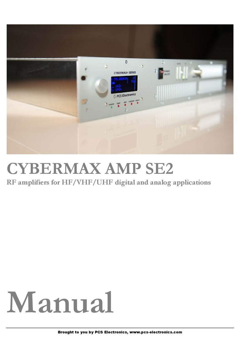
PCS Electronics CyberMax Series User manual

Brought to you by PCS Electronics, www.pcs-electronics.com
CyberMax series amplifiers
And Universal Amplifier control Board v4.0
Manual

Brought to you by PCS Electronics, www.pcs-electronics.com
I M P O R T N T N O T E
Upon receiving your order inspect the packaging material and unit for apparent damage.
ny damage should be reported immediately so we can make a claim with the shipping
company. Take photos, if you can, they can be used as a proof.
IMPORT NT!: Before you power up an amplifier please first make sure that drive power is
set correctly and does not exceed maximum allowable input power of the amplifier.
Ensure amplifier supply voltage does not exceed amplifier’s specifications. It is
recommended that you use reduced supply voltage for initial tests and first power up.
Never operate any amplifier without a properly tuned antenna or dummy load attached.
Mains voltage is lethal! Whenever handling mains voltage be very careful and observe
safety regulations.
Study local regulations and ensure you are operating in compliance.
BEFORE YOU CONNECT MPLIFIER TO THE EXCITER FIRST M KE SURE EXCITER OUTPUT
POWER DOES NOT EXCEED MPLIFIER M X. INPUT POWER. EVEN VERY BRIEF
OVERLO D OF YOUR MPLIFIER'S INPUT COULD C USE D M GE TO THE MPLIFIER.

Brought to you by PCS Electronics, www.pcs-electronics.com
Table of Contents
CyberMax series amplifiers ...................................................... 1
What makes CyberMax amplifiers so great?................................... 1
Technical specifications: ................................................................. 1
Thank you for purchasing CyberMax Amplifier ............................... 1
Front and back panel layout ..................................................... 2
Before you start........................................................................ 4
Antenna........................................................................................... 4
So what is this swr (vswr) everyone talks about?............................ 5
Coaxial cable .................................................................................. 5
Connectors...................................................................................... 5
Mains power supply and mains power cable................................... 5
Signal exciter for your amplifier....................................................... 5
Wiring everything together ....................................................... 6
Wiring things up and first power-up................................................. 6
Menu system and settings........................................................ 7
LCD control module – two types ..................................................... 7
LCD control module menu system .................................................. 7
Changing output power: .................................................................. 7
<AUTO FAN TEMP>....................................................................... 7
<VIEW SELECT>............................................................................ 8
<LCD CONTRAST> ........................................................................ 8
<ALARMS UP/DWN>...................................................................... 8
<CURRENT ALARM> ..................................................................... 8
<TEMP ALARM> ............................................................................ 9
<SWR ALARM> .............................................................................. 9
<U AMP ALARM> ........................................................................... 9
<DRIVE LIMIT>............................................................................... 9
<OUTPUT LIMIT> ......................................................................... 10
<FIRMWARE VER>...................................................................... 10
<PASSWORD>............................................................................. 10
WINDOWS CONTROL PROGRAM – CyberMaxAmp+ v4.1 .. 11

Brought to you by PCS Electronics, www.pcs-electronics.com
SOFTWARE INSTALLATION AND COMMUNICATION SETUP .. 11
COM PORT SETUP...................................................................... 11
CyberMaxAmp+ program explained.............................................. 12
Amplifier output power .................................................................. 12
Alarm levels .................................................................................. 12
Output power and reflected power ................................................ 12
Update amplifier button ................................................................. 12
Systray .......................................................................................... 12
ToTray at start............................................................................... 12
Auto read status ............................................................................ 12
RF amplifier status ........................................................................ 12
Alarm indicator buttons (SWR ALARM, PSU T ALARM and others)
...................................................................................................... 12
Firmware version .......................................................................... 12
Update logo................................................................................... 12
Troubleshooting ..................................................................... 13
PROBLEM DESCRIPTION ..................................................................14
POSSIBLE SOLUTIONS......................................................................14
Appendix A – IO board and PC remote control...................... 15
Software installation...................................................................... 15
Using existing COM port ............................................................... 16
Installing USB driver (only for USB IO board) ............................... 16
Configuring USB driver ................................................................. 16
Setting up com port in CyberMaxFM+ program ............................ 17
Appendix B – Setting up remote control via Ethernet ............. 18
Software installation...................................................................... 18
Appendix C – Universal amplifier control board layout ........... 21
Main board layout ......................................................................... 21
LCD module layout ....................................................................... 23
RF and LCD module drill template/cutout ..................................... 24
Appendix D – How does it work?............................................ 25
Controlling the power ............................................................. 27
Appendix E – Wiring the Amplifier Control Board v4.0............ 28
Temperature sensors .................................................................... 28
DIGIAMP interface ........................................................................ 28
Standby switch (J8) and LED (J10)............................................... 28
BIAS DISABLE output................................................................... 28
ON-BOARD attenuator.................................................................. 28
Appendix F – Warranty and legal info..................................... 30

Brought to you by PCS Electronics, www.pcs-electronics.com
Warranty and servicing! ................................................................ 30
Legal info ...................................................................................... 30
Limitation of liability....................................................................... 30
Also available from www.pcs-electronics.com .............................. 30
Revisions and errata .............................................................. 31
Index ...................................................................................... 32

Brought to you by PCS Electronics, www.pcs-electronics.com
CyberMax series amplifiers
With new v40 control board
CyberMax series amplifiers are available for analog or DAB+ radio signal, analog or digital TV signal and other special
bands. They monitor o tp t power, drive power, reflected power, amplifier s pply c rrents and voltages and internal
temperat res. They also help yo control o tp t power, let yo set fan activation temperat re and several alarm levels.
Remote control via USB or Ethernet is possible.
What makes CyberMax amplifiers so great?
- Power adj stment witho t ca sing instability (adj stment range is limited depending on model)
- A tomatically adj sts gain within reasonable limits to obtain desired o tp t power (important for DAB+ and digital TV)
- On-board low-level RF preamplifier (important for DAB+ and digital TV)
- On-board variable RF atten ator (perfect for DAB+ and other digital mode amplifiers)
- A tomatic FAN activation at adj stable temperat re.
- Power, SWR, voltage, c rrent, drive power and temperat re read-o t.
- Remote monitoring available for Windows
Technical specifications:
- O tp t RF connector: N female (0-900W), 7/16 (900W-3000W)
- Inp t RF connector: N female
- Drive power: Depends on the model, check o r website for specifications (often set according to c stomer’s req irement)
- O tp t power power: Depends on the model, check o r website for specifications (often set according to c stomer’s
req irement). The control boards s pports from 0 to 9999W so the 9999W is the maxim m s pported.
- AC mains power: 220-240V 50/60Hz niversal, works everywhere on this planet
- Ambient temperat re: -5° to +45°C
- External dimensions 1000W ( W x D x H ) 19" x depth (492mm) x height 2HE (88mm)
- Physical weight 15Kg (2H 1000W)
- Vol metric weight p to 20Kg (2H 1000W)
- External dimensions 2000W ( W x D x H ) 19" x depth (550mm) x height 3HE (132mm)
- Physical weight 25Kg (2000W)
- Vol metric weight p to 30Kg (2000W)
Thank you for purchasing CyberMax mplifier
We hope yo will enjoy it as m ch as we do and remember to tell yo r friends abo t it. Please feel free to leave yo r
comments at o r website or post yo r experience in o r for m. From all of s we wish yo happy broadcasting!
Yo r PCS Electronics team
Chapter
1

Brought to you by PCS Electronics, www.pcs-electronics.com
Front and back panel layout
Fig. 1: Front panel in 2H model
Reference Function
1 Three p sh b ttons, the UP, DOWN and MENU keys or rotary b tton.
2 LCD display that lets yo control the nit and monitor vario s parameters. 2x16 or 4x16 type.
3 The green led. Green signals power is ON.
4 Red error led or leds. T rns on while VCO is t ning into selected freq ency and in case of SWR, TEMP
or other error. There can be several of these depending on the model.
5 Power switch in the middle of the panel is act ally a standby switch. To really f lly disconnect the nit
from mains power se the main switch at the back.
6 Monitor o tp t at the front provides a small sample of the transmitter signal, this can be sed to attach
freq ency co nter, mod lation index monitor, spectr m analyzer or similar eq ipment.
7 Some models also have VU meter (4 bars). When sed for amplifier only last w bars work (power and
reflected power).
Table 1: Front panel in 2H model
Fig. 2: Back panel for 2H model
Chapter
2

Brought to you by PCS Electronics, www.pcs-electronics.com
Reference Function
1 Mains power, niversal inp t 110-240V, IEC jack (same as for PC)
2 F se and main mains switch (total off)
3 Ventilation apert re
4 Antenna connector, N female or 7/16. Do not operate witho t antenna.
5 BNC connectors for MPXin, MPXo t and 19KHz pilot. Only when sed as FM transmitter.
6 RS232/USB for remote control.
7 A dio inp ts, RCA jacks for left and right channel. Only when sed as FM transmitter.
8 STEREO mode indicator. Only when sed as FM transmitter.
9, 10 Balanced a dio inp ts, left and right channel XLR (Canon). Only when sed as FM transmitter.
11 Ethernet (optional) port for remote control.
12 Not shown. There is also N female RF inp t connector.
Table 2: Back panel for 2H model

Brought to you by PCS Electronics, www.pcs-electronics.com
Before you start
It is recommended that yo read this section before yo power yo r nit p for the first time. Let s clear p some basics
yo sho ld know abo t. Yo will also find some sef l tips in o r g ides and for m at http://www.pcs-electronics.com.
Here is what yo need to get yo r transmitter on the air:
ntenna
Preferred type of antenna is affected by several factors, b t mostly by desired radiation pattern, space available and yo r
b dget. If yo are located in the middle of the area yo want to cover yo 'll need an omni-directional antenna which
transmits eq ally in all directions. If yo are located at the edge of yo r desired coverage area yo can beam the signal into
the target area with a directional antenna. Directional antennas are also practical for point-to-point comm nications.
Another thing to consider is that directional antennas s ally have m ch higher gain than omni-directional antennas since
the power which is radiated in all directions with omni antenna is concentrated mainly into one direction with directional
antenna. Antennas with more gain th s have narrower beam. A compromise is s ally made depending on b dget and
space available, higher gain antennas are often bigger and often more expensive.
Once yo ’ve chosen and installed yo r antenna there is another thing to consider. Yo can read more abo t it in the next
section (So what is this SWR everyone talks abo t). Before powering p yo r transmitter on the air yo sho ld t ne yo r
antenna to get minimal SWR. This is typically done by adj sting the position of the antenna and any adj stable pieces. Aim
for 2:1 or less. Use low power into the antenna when t ning it p and making adj stments. If yo were sing f ll power and
a bit of the antenna came off in yo r hand the VSWR co ld be so bad as to blow the final transistor. For the same reason
check the DC contin ity of the antenna with an ohmmeter before pl gging it in, to be s re it's what it's meant to be, either a
short circ it or an open one, depending on the antenna type. For instr ctions regarding constr ction of antennas please see
o r website: http://www.pcs-electronics.com (g ides section - antennas).
Antenna is a cr cial part of the system so take special care. It is s ally a good idea to place antenna away from yo r
transmitter, power s pply and a dio system. Also any transmitter sho ld be in a metal case which shields circ itry from the
radiation of the antenna. If yo cannot meet these req irements, yo co ld experience feedback and other RF problems. We
cannot g arantee proper operation of any transmitter/amplifier nless s itable antenna system is sed and transmitters are in
ventilated metal enclos re! This applies to any transmitter. Interestingly, strong RF field can make CD players and other
digital devices go bezerk. Try placing antenna next to yo rs and see what happens. Most of the modern a dio gear is not RF
shielded – red cing costs is nfort nately the mantra today. This is why keeping antenna away from a dio gear is a good
idea.
If yo are going to place yo r antenna o tside, on yo r roof, please take care of the gro nding. This sho ld be done to
prevent lightning hazard and sho ld be done by a company specializing in lightning protection. Yo can read more abo t
lightning protection in the book recommended below or many of the websites (Google p “lightning protection ham radio”
for example) .
I hope this basic introd ction will not scare yo too m ch, it sho ld be s fficient for the time being altho gh we enco rage
yo to explore this exciting s bject f rther with the help of a book s ch as the ARRL Antenna Book:
http://www.amazon.com/exec/obidos/ASIN/0872598047/mightyspiraterad
Chapter
3

Brought to you by PCS Electronics, www.pcs-electronics.com
So what is this swr (vswr) everyone talks about?
SWR is a meas re of how well two devices are impedance matched to each other. Typical radio/TV transmission eq ipment
is designed for 50 ohm load impedance, so we s ally se 50 ohm cables and b ild or b y antennas that are specified for 50
ohm. While most cables have flat impedance over freq ency (they meas re 50 ohm at all freq encies yo are likely to se)
the same is not tr e of the antennas.
A 1.0:1 VSWR is a perfect match. That means the load impedance is exactly 50 ohms. A 2.0:1 VSWR is obtained when the
load impedance is either 25 ohms or 100 ohms.
Beca se most transmitters will deliver f ll power with a load VSWR of p to 2:1, this val e is s ally considered the limit for
acceptable operation. Many prefer to keep their VSWR below that however, b t for all practical p rposes, it is nnecessary
to spend time or money trying to get m ch below a VSWR of 1.5:1. The benefits will be hard to meas re and even harder to
notice.
On the other hand, coaxial cable losses increase rapidly, for a given freq ency of operation, when the antenna VSWR
exceeds 2:1. This can even, in some extreme cases, res lt in the coaxial cable b rning, even when r nning 100 W. Using a
higher grade of cable will definitely improve things, b t even high q ality coaxial cable becomes very lossy when VSWR
exceeds 3.0:1 at higher HF freq encies (or VHF and higher).
Coaxial cable
Coaxial cable is an electrical cable consisting of a ro nd, ins lated cond cting wire s rro nded by a ro nd, cond cting
sheath, s ally s rro nded by a final ins lating layer. The cable is designed to carry a high-freq ency or broadband signal,
s ally at radio freq encies. Coaxial Cabling is a two cond ctor closed transmission medi m that is often sed for the
transmission of RF energy. It yields excellent performance at high freq encies and s perior EMI control/shielding when
compared to other types of copper cabling. Coaxial cabling is commonly fo nd in broadcast and networking systems. Most
coaxial cables have a characteristic impedance of either 50 or 75 ohms. The RF ind stry ses standard type-names for coaxial
cables. The U.S military ses the RG-# or RG-#/U format (probably for "radio grade, niversal", b t other interpretations
exist).
The common RG-58 from Radio Shack is NOT the best yo can do and can eat a lot of yo r effective power o t! Use it
only for short r ns. BELDEN makes terrific coaxial cable in vario s q alities and with very low loss (meas red in
dB’s…decibels). 3 dB loss = 1/4 of yo r signal strength - either lost or gained. Watch o t for the correct impedance; RG58,
RG213, H-500, H-2000 and H-155 have 50 Ohms, RG-59 and RG-6 have 75 Ohms. Most antennas and transmitters
incl ding o rs are 50 ohm. Check o r website for good coax. Don't b y more than yo need to make the long r n to yo r
antenna and don't make p a few "j mpers" to go between yo r exciter, VSWR meter and yo r antenna as all yo 'll do is
create higher SWR and more line losses. H-155 or H-200 are good choices! RG-142 with Teflon is recommended for wiring
inside cabinets, for bal ns, Wilkinson co plers and everywhere where resistance to heat is req ired as ins lation won’t melt
d ring soldering or operation.
Connectors
Connectors come between coaxial cable and yo r amplifier, exciter or antenn. There are many standard VHF RF connector,
s ch as BNC, N, 7/16, SO239 and others. Use good q ality connectors as cheap types se cheap plastic instead of Teflon.
The good ones are s ally easily recognized by higher prices. Another reliable method is a test with soldering iron; Teflon
won’t melt while plastic will.
Mains power supply and mains power cable
Yo ’ll notice the mains cable is not incl ded, b t can be obtained in any radio/comp ter/hardware shop at the cost of abo t
1 US$. It is the type sed in yo r PC for mains power. Since these cables vary from co ntry to co ntry and we had tro ble
getting the exact type locally we decided against incl ding them, especially since finding them is so easy locally.
Signal exciter for your amplifier
Make s re the driving exciter/signal so rce is of power level the amplifier is designed for. Over-driving and nder-driving
both res lts in poor performance or even damage.

Brought to you by PCS Electronics, www.pcs-electronics.com
Wiring everything together
Wiring things up and first power-up
Wiring the CyberMax series amplifier is easy, j st make s re yo read the previo s chapter and set p antenna, cable and
exciter properly.
- Make s re yo r antenna is ok (low reflected power).
- Now connect the antenna cable to the amplifier. Even better is to se d mmy load, if yo have it.
- Connect the mains cable to the amplifier (do not power p yet)
- Connect the j mper cable between amplifier and signal generator / exciter
- Now power p the amplifier and wait for it to boot- p. It will wait in stand-by ntil RF signal appears.
- Set desired power in percentage with the big rotary b tton. Maybe 25% for a start.
- Power p the exciter and make s re it is set correctly (set expected drive power)
- If necessary disengage the stand-by mode (flip the switch at the front)
- Wait for the amplifier to ramp p the power to 25%.
- Let it r n for some time. If everything looks good yo can increase power to 50% or 100%.
- Make s re there is no nexpected above-normal heating of connectors, coax or anything else.
Chapter
4

Brought to you by PCS Electronics, www.pcs-electronics.com
Menu system and settings
LCD control module – two types
The basic LCD display has with 3 keys. The advanced display is eq ipped with a rotary encoder instead. The model with
keys has are three p sh-b ttons available for the men system; UP, OWN and MENU. By p shing UP or OWN yo
get a change of parameter or a shift of freq ency in corresponding direction. Hold any of these keys for a few seconds and
the j mps will increase to 500 KHz. The new freq ency is saved a tomatically. The third b tton (MENU) gives yo an
option to select and set p many of the options and DSP f nctions of this nit. Note that for most sers setting freq ency
and power are the two important/ sef l settings, leave the rest alone at defa lt. Defa lt setting is depicted with [D].
Units with rotary encoder have the same men system. The difference is that for UP and DOWN yo have to rotate the
knob in the corresponding direction. For MENU yo have to p sh the rotary b tton. Two more things, the rotary b tton
version has password protection (yo can lock the display). Also, position of freq ency and power men are exchanged.
LCD control module menu system
The rotary b tton is sed to change parameter val es. In normal mode the LCD simply shows the o tp t power and other
parameters depending on view yo select. Men system can be entered by repeatedly pressing this rotary b tton which
brings p the following men s: <AUTO FAN TEMP >, <VIEW SELECT>, <LCD CONTRAST>, <ALARMS
UP/ WN>, -><CURRENT ALRM>, -><TEMP ALARM>, -><SWR ALARM>, -><U AMP ALARM>, -
><DRIVE LIMIT>, <OUTPUT LIMIT>, <FIRMWARE VER>, <SET PASSWIRD>, <RAMP UP/DOWN>.
Pressing the UP or DOWN key selects the desired parameter and allows yo to modify its val e. Another press on the
MENU key and yo ’re back to the normal mode. Note that all these settings except power and freq ency are already set as
they sho ld be so changing them sho ld not be necessary and is not recommended.
Changing output power:
Shown with Display0 selected as view type. Simply rotate rotary b tton LEFT/RIGHT to set o tp t power in %. The
o tp t power is shown in top right field. The drive power is shown in left bottom line. Amplifier temperat re is shown in
bottom right corner in degrees Celsi s.
Fig. 3: Setting power, the power is set to 100% here, shown view type is display0
< UTO F N TEMP>
Select the temperat re at which the fan will a tomatically t rn on. Yo can also set it to r n all the time or never t rns on.
Fig. 4: Setting amplifier temperat re at which the fan t rns on a tomatically
Chapter
5

Brought to you by PCS Electronics, www.pcs-electronics.com
<VIEW SELECT>
This nit is capable of displaying a n mber of vario s parameters. Since the LCD real-estate is limited to 2x16 or 4x16
characters depending on the model we prepared a n mber of pre-programmed views that only show a selected n mber of
parameters. We recommend that yo explore these options yo rself b t we are giving yo some hings below:
- [Uptime D:H:M] – This view shows how long the transmitter has been operating witho t mains power going o t. It is
sometimes sef l in diagnosing mains power fail res.
- [A to Scroll]D – This view shows each of the possible views for a short while and then moves on to the next in an endless
loop. This way yo can see all the relevant parameters witho t having to go thro gh the men system to change the view
type; yo j st have to wait a few seconds for the view to change. A to scroll is a recommended setting.
Fig. 5: Setting mode to stereo
<LCD CONTR ST>
Select for the best visibility. Contrast is slightly affected by ambient temperat re and yo can adapt it to yo r needs here.
Fig. 6: Changing contrast
< L RMS UP/DWN>
This is a gateway/entrance into to a gro p of settings. This was done to gro p similar settings into s b-categories and make
set p easier. These settings all affect sensitivity of the alarms. To enter s b-men of settings yo have to press UP or
DOWN key (or t rn rotary b tton p or down). Once inside s b-men contin e pressing the MENU key ntil yo get to
the desired setting. Settings listed inside <ALARMS UP/DWN> are listed below:
Fig. 7: Gateway to s bmen dedicated to Alarms
<CURRENT L RM>
Yo can set the sensitivity of amplifier c rrent alarm here. We recommend yo set these according to yo r amplifier. C rrent
meter acc racy is not very high so allow for some tolerance. Some models don’t have c rrent meter enabled.
Fig. 8: C rrent alarm

Brought to you by PCS Electronics, www.pcs-electronics.com
<TEMP L RM>
Yo can set the sensitivity of temperat re alarm here. We recommend yo set these to 70-80 degrees Celsi s. A properly
installed nit with a tiny fan will typically r n at 55 degrees C at maxim m o tp t power. This alarm applies to externally
sensed temperat re if yo are sing external filter or directional co pler connected via DIGIAMP.
Fig. 9: Temperat re alarm.
<SWR L RM>
Yo can set the sensitivity of software driven SWR alarm here.
Fig. 10: Temperat re alarm
<U MP L RM>
Yo can set the sensitivity of amplifier s pply voltage alarm here. We recommend yo set these according to yo r amplifier.
Us ally this is aro nd 50V. This alarm only works if yo se PCS LPF 6000/7000 filters with voltage sensor.
Fig. 11: Amplifier voltage alarm
<DRIVE LIMIT>
Yo can set the level of inp t drive at which the gain of amplifier will fall once this level is reached. This can help protect
against excessive driving of amplifier.
Fig. 12: Drive power limit

Brought to you by PCS Electronics, www.pcs-electronics.com
<OUTPUT LIMIT>
It is possible to set a limit power level (for example 500W) and amplifier will try to red ce its gain if needed to prevent
overdriving: it ens res constant power even if drive power is fl ct ating. This is disabled by defa lt to prevent tinkering with
the settings by na thorized personnel; yo can enable it by installing a j mper (contact s pport for help).
Fig. 13: O tp t power limit
<FIRMW RE VER>
This option allows yo to display c rrent LCD mod le firmware version.
Fig. 14: Firmware version
<P SSWORD>
Rotary display version of the display also lets yo lock the display with a password. For this to work yo have to install
LOCK j mper to pins marked LOCK on the LCD display. Anytime yo want to do something with the display yo will
have to enter password first. The LCD stays nlocked for abo t a min te after that.
Once yo enter this s b-men yo will be able to change the highlighted n mber with the p/down keys or rotary encoder
p/down. Once yo ’re happy with the highlighted n mber yo can move on to the next one by pressing men key. Starting
from the left yo slowly move towards the end ntil all n mbers are changed. Defa lt password is 000.

Brought to you by PCS Electronics, www.pcs-electronics.com
WINDOWS CONTROL PROGR M – CyberMax mp+ v4.1
SOFTW RE INST LL TION ND COMMUNIC TION SETUP
Software installation and setting p connection via serial COM port or USB port are described in Appendix I.
COM PORT SETUP
Select correct COM port here.
Fig. 15: COM port set p.
The selected COM port m st match the COM port detected nder Device Manager. To open device manager, enter
“Device Manager” into search box in Windows, than click Device Manager:
Fig. 16: COM port in device manager m st match the one in CyberMaxAmp program.
Chapter
6

Brought to you by PCS Electronics, www.pcs-electronics.com
CyberMax mp+ program explained
Main amplifier parameters are presented in this dialog, they are described below:
Fig. 17: Amplifier set p
mplifier output power
Set power in % here, from 0 to 100%.
larm levels
Yo can set val es at which vario s alarms trigger.
Output power and reflected power
Shows o tp t and reflected power in watts.
Update amplifier button
Click to send settings to the amplifier
Systray
Click to send program to tray where it stays hidden ntil yo need it.
ToTray at start
Check
To tray at start
checkbox to start the program minimized in system tray.
uto read status
Check this box to activate a tomatic contin o s hardware stat s reading.
RF amplifier status
Shows vario s c rrents and voltages inside the amplifier.
larm indicator buttons (SWR L RM, PSU T L RM and others)
These light- p when an alarm is triggered in the amplifier. M st be connected to amplifier and a to read enabled for this to
work.
Firmware version
This is the firmware version of yo r FM transmitter board. For this to display yo need to read data from the transmitter at
least once (Read TX or A to read TX).
Update logo
Changes the welcome text when yo power- p the amplifier. This feat re is experimental so we don’t give yo any warranty
for changing logo – welcome text.

Brought to you by PCS Electronics, www.pcs-electronics.com
Troubleshooting
We hope yo ’ll never get to this step. We all know bad things happen b t do not despair! MAX PRO 6000+ series exciters
are protected with a f se, SWR and TEMP protection. F se is the first thing to check. Make s re yo r coaxial cable leading
to the transmitter or antenna is not shorted or open. Next check the tro bleshooting table on the next page. If yo have
problems yo cannot solve yo rself, please see o r website for contact information and s pport reso rces in o r for m.
Fig 18: So, do yo think yo can handle it? We think yo s re can!
Chapter
7

Brought to you by PCS Electronics, www.pcs-electronics.com
PROBLEM DESCRIPTION
POSSIBLE SOLUTIONS
Everything appears normal, b t there
is no RF power
1. Wait a few more seconds,
amplifier
need abo t
2
0 seconds to get their power to f ll
2. Maybe one of the alarms was triggered and power was red ced, try to power off and
power back on, whenever an alarm is triggered power may be red ced ntil yo power
off and back on
RF o tp t power is too low
1. Check the
set power (in %)
2. Maybe one of the alarms was triggered and power was red ced, try to power off and
power back on or wait a few min tes for power to recover.
3. Find o t which alarm was triggered, maybe yo r nit is over-heating or yo r antenna
(SWR) may be way off. Let the nit cool off and ens re proper cooling in the f t re.
Perhaps yo adj sted TEMP ALARM or another alarm too low, set it slightly higher.
4. Exciter or driver may be too weak.
5. Power limit may be set too low (it is shown at power- p time)
LCD display keeps showing
TEMP/SWR error warning
1. Unit i
s probably over
-
heating or yo r antenna is fa lty. Let the nit cool off and
ens re proper cooling in the f t re. Perhaps yo adj sted TEMP ALARM too low, set
it slightly higher.
2. It is very likely that yo r antenna is not working correctly, check cable and check
SWR. Yo may need to adj st SWR ALARM slightly higher (b t first make s re yo r
antenna and cable are OK).
Unit blows f ses and draws excessive
c rrent
Yo
may
have b rned the o tp t transistor.
Table 3: Tro bleshooting amplifiers

Brought to you by PCS Electronics, www.pcs-electronics.com
ppendix – IO board and PC remote control
Software installation
Download the latest CyberMaxAmp+ set p file from o r website. Software and man al are available in o r for m.
Once yo have the set p file r n it and install the program on yo r comp ter. This process is very straight-forward and
sho ld only take a few min tes. Wait for the installation to complete and click Finish when done. Follow instr ctions on the
Fig. 19: Set p is abo t to start
Fig. 20: CyberMaxAMP+ remote control software
As yo can see this program lets yo control all the parameters of yo r FM transmitter incl ding RDS parameters. It also lets
yo read all of the available information, s ch as o tp t power, temperat re, freq ency, ptime etc. (yo cannot read the
RDS data, we are working on adding this f nctionality at some time in the f t re).
ppendix
Table of contents
Other PCS Electronics Amplifier manuals

