PCS Electronics CYBERMAX AMP SE2 User manual

Brought to you by PCS Electronics, www.pcs-electronics.com
CYBERMAX AMP SE2
RF amplifiers for HF/VHF/UHF digital and analog appli ations
Manual

Brought to you by PCS Electronics, www.pcs-electronics.com
I M P O R T N T N O T E
t the time of receiving your order inspect the packaging material and unit for apparent
damage. ny damage should be reported immediately at the time of delivery with the
delivery service employee so we can make a claim with the shipping company later. lso
take photos; they may be used as a proof later.
IMPORT NT! Before you power up an amplifier please first make sure that drive power is
set correctly and does not exceed maximum allowable input power of the amplifier.
IMPORT NT! Never operate any amplifier without a properly tuned antenna or dummy load
attached.
IMPORT NT! Mains voltage is lethal! Whenever handling mains voltage be very careful and
observe safety regulations.
Study local regulations and ensure you are operating in compliance.
M KE SURE EXCITER OUTPUT POWER DOES NOT EXCEED MPLIFIER M XIMUM INPUT
POWER. EVEN VERY BRIEF OVERLO D OF YOUR MPLIFIER'S INPUT COULD C USE
D M GE TO THE MPLIFIER.
DO NOT FORGET TO CONNECT NTEN BEFORE YOU POWER UP THE MPLIFIER!

Brought to you by PCS Electronics, www.pcs-electronics.com
Table of Contents
Introducing the CYBERMAXAMP SE+ ..................................... 1
What makes this rack mounted amplifier so great? ........................ 1
Technical specifications: ................................................................. 1
RF section specifications for VHF model (Analog FM radio):.......... 1
RF section specifications for DAB+ model (digital FM radio): ......... 2
RF section specifications for analog TV model: .............................. 2
RF section specifications for digital TV model:................................ 2
Thank you for purchasing CYBERMAXAMP SE+ Amplifier ............ 2
Front and back panel layout ..................................................... 3
Using the CYBERMAXAMP SE+ Amplifier............................... 5
Lcd control module.......................................................................... 5
Lcd control module menu system ................................................... 5
Changing output power................................................................... 5
[AUTO FAN TEMP] ......................................................................... 6
[VIEW SELECT].............................................................................. 6
[SWR ALARM] ................................................................................ 6
[AMP TEMP ALARM]...................................................................... 6
[PSU TEMP ALARM] ...................................................................... 6
[CURENT ALARM].......................................................................... 6
[LCD CONTRAST] .......................................................................... 6
[SET PASSWORD] ......................................................................... 6
[OUTPUT LIMIT] ............................................................................. 6
Troubleshooting .............................................................................. 6
WINDOWS CONTROL PROGRAM – CYBERMAXAMP+........ 8
SOFTWARE INSTALLATION AND COMMUNICATION SETUP .... 8
Configuring communications port.................................................... 9
Installing USB driver (only for USB IO board) ............................... 10
Configuring USB driver ................................................................. 10
Appendix B – Setting up remote control via Ethernet ............. 11

Brought to you by PCS Electronics, www.pcs-electronics.com
Software installation...................................................................... 11
Appendix C – Warranty and legal info .................................... 14
Warranty and servicing! ................................................................ 14
Legal info ...................................................................................... 14
Limitation of liability....................................................................... 14
Also available from www.pcs-electronics.com .............................. 14
Revisions and errata .............................................................. 15
Index ...................................................................................... 16

Brought to you by PCS Electronics, www.pcs-electronics.com
Introducing the CYBERM X MP SE+
New family of our rack mounted amplifiers with new control board and many new features
Is your signal too weak? Boost it with this reliable and practical amplifier. It is very easy to use yet also provides all the bells
and whistles. This versatile and reliable new amplifier lets you monitor and set output power, monitor drive power, output
power, reflected power, several amplifier supply currents & voltages and 2 temperatures. ou can also set fan activation
temperature and several alarm levels. It also allows remote control via RS232, USB or Ethernet (optional upgrade).
What makes this rack mounted amplifier so great?
- Enables power adjustment without causing instability
- It automatically adapts the gain to your drive power - within reasonable limits, to obtain desired power output
- Supports up to 9,9KW (depending on the model)
- High-gain versions are available for DAB+ and DTV (digital TV)
- Models available for analog and digital FM radio, analog and digital TV or other HF/VHF/UHF services
- Can monitor up to 4 voltages and 4 currents
- Supports new 65V DC mains power supply models
- Automatic FAN activation at adjustable temperature.
- Power, SWR, voltage, current, drive power and temperature read-out.
- Remote monitoring available via USB, RS232 or Ethernet, communication protocol is available for free
Technical specifications:
- General power range for all models: 0 – 9900W (can be expanded if needed)
- Mains power: worldwide universal 110-240V 50/60Hz
- Ambient temperature: -5° to +45°C
- Over-current protection, overvoltage protection, overdrive protection, temperature protection
- Rack size depends on power rating, 2H and 3H units
RF section specifications for VHF model ( nalog FM radio):
- Output power: 200W/400W/600W/800W/1000W/1500W/2000W/3000W/5000W/10000W
- Output: 50 ohm (N female or 7/16 connector)
- VSWR less than 2:1 for full output
- Input connector: N female or BNC
- Drive power: 1W-20W depending on the model
- Frequency range: 87.5 to 108MHz
- RF Harmonics > -60 dBc Standard
- External dimensions 200W/400W ( W x D x H ) 19" x depth (170mm) x height 2HE (88mm), weight ~10Kg
- External dimensions 600W, 800W ( W x D x H ) 19" x depth (170mm) x height 2HE (88mm), weight ~12Kg
Chapter
1

Brought to you by PCS Electronics, www.pcs-electronics.com
- External dimensions 1000W, 1500W ( W x D x H ) 19" x depth (492mm) x height 2HE (88mm), weight ~15Kg
- External dimensions 2000W ( W x D x H ) 19" x depth (550mm) x height 3HE (132mm), weight ~25Kg
RF section specifications for D B+ model (digital FM radio):
- Output power: 25W (150W pp) or 400W (1200W pp)
- Output: 50 ohm (N female or 7/16 connector)
- VSWR less than 2:1 for full output
- Input connector: N female or BNC
- Drive power: 0.1mW to 10mW (high gain model) or 2-5W (regular model)
- Frequency range: 175MHz to 225MHz
- RF Harmonics: Mask filter not included
- External dimensions 25 ( W x D x H ) 19" x depth (170mm) x height 2HE (88mm), weight ~10Kg
- External dimensions 400W ( W x D x H ) 19" x depth (550mm) x height 3HE (132mm), weight ~25Kg
RF section specifications for analog TV model:
- Output power: 200W/400W/600W/1000W
- Output: 50 ohm (7/16 connector)
- VSWR less than 2:1 for full output
- Input connector: N female
- Drive power: 1W-20W depending on the model
- Frequency range: 175-855MHz depending on the model
- External dimensions 200W
- External dimensions 400W, 600W ( W x D x H ) 19" x depth (170mm) x height 2HE (88mm), weight ~12Kg
- External dimensions 1000W ( W x D x H ) 19" x depth (492mm) x height 2HE (88mm), weight ~15Kg
RF section specifications for digital TV model:
- Output power: 50W or 250W (1000W pp)
- Output: 50 ohm (7/16 connector)
- VSWR less than 2:1 for full output
- Input connector: N female
- Drive power: 0.01mW to 10mW
- Frequency range: 470MHz to 855MHz
- RF Harmonics: Mask filter not included
- External dimensions 50W ( W x D x H ) 19" x depth (170mm) x height 2HE (88mm), weight ~10Kg
- External dimensions 250W ( W x D x H ) 19" x depth (550mm) x height 3HE (132mm), weight ~25Kg
Thank you for purchasing CYBERM X MP SE+ mplifier
We hope you will enjoy it as much as we do and remember to tell your friends about it. Please feel free to leave your
comments at our website or post your experience in our forum. From all of us we wish you happy broadcasting!
our PCS Electronics team

Brought to you by PCS Electronics, www.pcs-electronics.com
Front and back panel layout
Fig. 1: Front panel for 3H model, 2H model is very similar
Referen e Fun tion
1 Control rotary button, everything is adjusted with this button
2 LCD display that lets you control the unit and monitor various parameters.
3 LED diodes showing power status, temp alarm, swr alarm, current alarm or general alarm.
4 Power switch in the middle of the panel is actually a standby switch. To really fully disconnect the unit
from mains power use the main switch at the back.
5 Monitor output at the front provides a small sample of the transmitter signal; this can be used to attach
frequency counter, modulation index monitor, spectrum analyzer or similar equipment.
6 VU bar meters. When used for amplifier they show drive power on two bars on the left. The third and
fourth bar are used for power and reflected power.
Chapter
2

Brought to you by PCS Electronics, www.pcs-electronics.com
Fig. 2: Back panel for 3H model, 2H model is very similar
Referen e Fun tion
1 Main mains switch (total off)
2 Mains power, universal input 110-240V, IEC jack (same as for PC)
3 Exchangeable power supply (you can replace it without any opening or soldering)
4 Antenna connector, 7/16 female. Do not operate without antenna.
5 N female for drive input
6 RS232/USB for remote control
7 Optional ETHERNET input
8 Optional DIGIAMP interface for easy connection to CyberMaxFM exciters

Brought to you by PCS Electronics, www.pcs-electronics.com
Using the CYBERM X MP SE+ mplifier
Power-up procedure
In order to have the auto-gain-adjustment function work correctly you have to follow proper power-up procedure:
1. Connect antenna
2. Connect mains power to amplifier (still powered off)
3. Using dummy load or antenna set exciter drive power in accordance with amplifier model
4. Connect exciter to amplifier and power it up
5. Power up the amplifier. If amplifier is in stand-by also press button on the front to return it from stand-by
6. Set desired output power with rotary button and wait for amplifier to adjust output (slow ramp-up).
7. Adjust any desired parameters as required
8. If you can’t reach rated output power please ensure antenna is well matched. If everything is OK you can try
to increase drive power a little.
9. If your output power is too high and amplifier is not able to regulate it so low (control range may be limited)
you can also reduce drive power slightly to obtain desired output.
10. IMPORTANT: Always follow this pro edure: First power up ex iter, only then the amplifier!
Lcd control module
There is a rotary button available on the left side of the display unit. ou can rotate this button LEFT, RIGHT or you can
PUSH it. By pushing it you enter the MENU system and move between the MENU options. LEFT and RIGHT let you
change the selected setting.
Lcd control module menu system
In normal mode the LCD simply shows the frequency and power or whatever view you select. Rotating left or right in this
mode will increase or decrease output power. Pressing the rotary button can be used to enter the menu mode, repeatedly
pressing this key brings up the following menus: [AUTO FAN TEMP], [VIEW SELECT], [LCD CONTRAST], ,
[ALARMS UP/DWN],[CURRENT ALARM], [TEMP ALARM], [SWR ALARM], [U AMP ALARM], [DRIVE LIMIT],
[OUTPUT LIMIT], [FIRMWARE VER], [SET PASSWORD] and [RAMP UP/DOWN]. Rotating LEFT/RIGHT key
selects the desired parameter and allows you to modify its value. Another press on the rotary button and you’re back to the
normal mode. Note that all these settings except power and frequency are already set as they should be so changing them
should not be necessary and is not recommended.
Note alarms are all gathered into deeper level of menu system (to reduce clutter). So when you get to [ALARMS UP/DWN]
you can either jump over the alarms submenues (if you press button you will move straight to drive limit) or enter the alarms
submenues by turning button left or right. Once in alarms submenues you can now select desired alarm menu by pressing
the button and turning LEFT/RIGHT to select it and than again LEFT/RIGHT to adjust value. It may sound a little
confusing right now but if you try it you will find that it works pretty well.
Changing output power
Chapter
3

Brought to you by PCS Electronics, www.pcs-electronics.com
Simply rotate LEFT/RIGHT to adjust power to desired percentage of max output power. Selected setting is displayed on
the LCD as a percentage. Power in watts is shown on the LCD next to this percentage. It may take a while for the amplifier
to adjust the power as it will adjust the gain to obtain desired power level.
Note: Rotating LEFT/RIGHT changes power also when you have set a view type which does not show set power output.
[ UTO F N TEMP]
This setting allows you to set automatic fan activation temperature. Select desired activation temperature. Setting this too
high may compromise reliability and long-term performance due to running at high temperature.
[VIEW SELECT]
Amplifier is capable of displaying a number of various parameters. Since the LCD real-estate is limited to 4x16 characters we
prepared a number of pre-programmed views that only show a selected number of parameters. ou can select desired view
to access all parameters. [Auto Scroll] shows each of the above listed views for a short while and than moves on to the next
in an endless loop. This way you can see all the relevant parameters without having to go through the menu system to
change the view type, ou just have to wait a few seconds for the view to change.
[SWR L RM]
This option allows you to set SWR alarm level.
[ MP TEMP L RM]
This option allows you to set AMP temp alarm level.
[PSU TEMP L RM]
This option allows you to set AMP temp alarm level.
[CURENT L RM]
This option allows you to set current alarm level.
[LCD CONTR ST]
LCD contrast adjustment.
[SET P SSWORD]
This option allows you to set password. For this to work a jumper must be installed on LCD module (jumper LOCK)
[OUTPUT LIMIT]
Set in factory, protects the unit from overdrive. If you change this it may damage the amplifier which is why this value is
protected.
Troubleshooting
We hope you’ll never get to this step. We all know bad things happen but do not despair! Check the troubleshooting table on
the next page. If you have problems you cannot solve yourself, please see our website for contact information and support
resources in our forum.

Brought to you by PCS Electronics, www.pcs-electronics.com
Fig 3: So, do you think you can handle it? We think you sure can!
PROBLEM DESCRIPTION POSSIBLE SOLUTIONS
LCD is completely dark. 1. Check the main switch at the back
2. Check main cable is firmly inserted
3. Check that mains power supply is fully inserted
Red LED constantly on Some kind of alarm is active. The LCD display will usually show which one.

Brought to you by PCS Electronics, www.pcs-electronics.com
WINDOWS CONTROL PROGR M – CYBERM X MP+
SOFTW RE INST LL TION ND COMMUNIC TION SETUP
Once you have the driver from our website run the setup file and install the program on your computer. The program is
available in our Forum where we keep all manuals and setup files. Installation process is very straight-forward and should
only take a few minutes. Wait for the installation to complete and click Finish when done.
Fig. 4: Setup is about to start
Once the installation is done you are ready to start the program. ou are now ready to establish connection with the
Universal Amplifier Control board and configure all the parameters.
ppendix

Brought to you by PCS Electronics, www.pcs-electronics.com
Fig. 5: Windows control program
As you can see this program lets you control all parameters of your universal amplifier board. It also lets you read all of the
available information, such as output power, temperature, frequency, uptime etc.
Configuring communications port
If you are using RS232 cable the only setup required is minimal. Start the program, the icon should now be on the desktop.
Now click File and setup. The following window will open. When using RS232 please set COM port to 1 or 2. These
settings are usually correct. If not, we will explain the installation and setup process for USB control cable and Ethernet in
more detail in next appendix..
Fig. 6: Set COM port to 1 for RS232 IO board
Brought to you by PCS Electronics, www.pcs-electronics.com
Installing USB driver (only for USB IO board)
Install the USB driver file that you can find on our website in the forum section for your product.
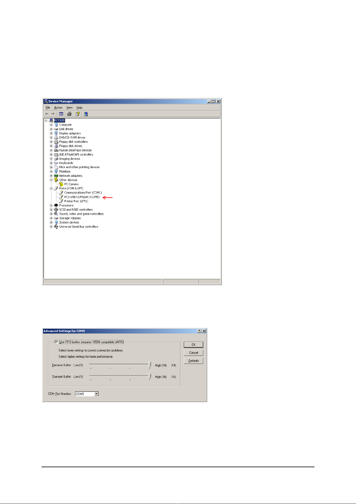
Configuring USB driver
In Windows go to Start > Settings > Control Panel > System > Hardware tab > Device Manager (This can vary depending
on your Windows version). ou should have something like this on your screen at this point:
Fig. 7: Configuring Com port for USB driver
Take note of the COM port number here, you will need it later to configure the COM port inside CyberMaxFM+ windows
control program. If you wish to change this port right click on the PCS USB-COM port and select Properties. Now select
the Port settings tab and click Advanced. Note you can set the COM port number as you wish:
Fig. 8: Configuring Com port for USB driver

Brought to you by PCS Electronics, www.pcs-electronics.com
ppendix B – Setting up remote control via Ethernet
Software installation
Download the latest EthernetVirtualPort.exe from our website. ou can find it here:
http://www.pcs-electronics.com/phpBB2/viewtopic.php?t=2268
Once you have the driver run the setup file and install the program on your computer. This process is very straight-forward
and should only take a few minutes. Wait for the installation to complete and then start the program.
Connect the MAXPRO5000 series exciter or C BERMAXFM+ FM transmitter (which contains this exciter board) to your
network via Ethernet cable (cable not included). The Ethernet adapter is setup to accept IP from your router’s DHCP
server. It is possible to setup Ethernet adapter with fixed IP or to login directly to ADSL modem. If you need MAC address
of the Ethernet adapter open the cover of the unit and look at the Ethernet adapter, the MAC address is shown on the
adapter. Now create and configure a connection between the PC and C BERMAXFM+ as shown below. Note the IP will
differ, but make sure the port is set to 5005!
Fig. 46: Setting up Ethernet connection for C BERMAXFM+, screen 1
ppendix
B

Brought to you by PCS Electronics, www.pcs-electronics.com
Fig. 47: Setting up Ethernet connection for C BERMAXFM+, screen 2
Fig. 48: Setting up Ethernet connection for C BERMAXFM+, screen 3

Brought to you by PCS Electronics, www.pcs-electronics.com
Fig. 49: Setting up Ethernet connection for C BERMAXFM+, screen 4
Fig. 50: Setting up Ethernet connection for C BERMAXFM+, overview

Brought to you by PCS Electronics, www.pcs-electronics.com
ppendix C – Warranty and legal info
Warranty and servicing!
Within one (1) year of receiving your order, if any product proves to be defective; please contact us via e-mail or our
feedback form. Please DO NOT ship the product back to us without contacting us first and receiving return instructions.
After we receive the defective merchandise, we will test it if need be, and we will ship back to you a non-defective
replacement product. Please note that this doesn't cover final RF transistor as it can be damaged by using defective or
poorly matched antenna. An exception is as well any mishandling or abuse by the customer. If the product is defective, you
will receive a replacement. If you choose to return the defective item, rather than replace it, we will charge a 20% restocking
fee and your original shipping and handling charges will not be refunded. The return of the product is at your expense. We
believe that this is a fair policy because lower overhead results in lower prices for all of our customers.
Legal info
It may be illegal to operate this device in your county. Please consult local authorities before using our products! PCS
Elektronik d.o.o. is not responsible for any damage to your PC arising from use of this product and will not be held
responsible for any violation of local laws pertaining to the use of this product. It is entirely your responsibility that you
make sure you operate in accordance with local laws and/or regulations.
Limitation of liability
To the law, in no event shall PCS Elektronik d.o.o. or its suppliers be liable for any special, incidental, indirect, or
consequential damages whatsoever (including, without limitation, damages for loss of business profits, business interruption,
loss of business information, or any other pecuniary loss) arising out of the use of or inability to use the PRODUCT, even if
PCS Elektronik d.o.o. has been advised of the possibility of such damages. In any case, PCS Elektronik d.o.o.´s entire
liability under any provision of this agreement shall be limited to the greater of the amount actually paid by you for the
PRODUCT or U.S. $5.00; because some states and jurisdictions do not allow the exclusion or limitation of liability, the
above limitation may not apply to you.
lso available from www.pcs-electronics.com
We also carry a big range of:
- FM transmitters in assembled and KIT form
- TV transmitters in assembled and KIT form, VHF and UHF
- AM transmitters with extremely clear modulation (PWM design)
- Various accessories for professional and hobby FM radio stations
- A large assortment of hard to obtain RF components (RF transistors; MRF, 2SC, coils, silver plated wire, coaxial cable,
capacitors, quartz crystals and many others)
- PC based FM transmitters (PCI MAX pc based FM transmitter turns your PC into a radio station)
- A large number of beginners guides to get you started
- A large selection of free schematics is as well available at our website.
If you can’t get much range with your homebrew antenna, have a look at these: http://www.pcs-electronics.com
ppendix
C

Brought to you by PCS Electronics, www.pcs-electronics.com
Revisions and errata
V1.0 (March, 2020): Release version
Please report any errors you see in this manual, you will be helping us and many other users out there. Thank you!

16
Index
Ethernet, 11
menu system, 5
Technical specifications, 1, 2
Troubleshooting, 6
This manual suits for next models
1
Table of contents
Other PCS Electronics Amplifier manuals


Popular Amplifier manuals by other brands


Bogen
Bogen MT60 manual

Marshall Amplification
Marshall Amplification MG GOLD SERIES owner's manual

ARC Audio
ARC Audio XXK Series owner's manual

Mesa/Boogie
Mesa/Boogie Three Channel Dual & Triple Rectifier Solo... operating manual

Aguilar
Aguilar AG 500-112C owner's manual

Gefen
Gefen 1x16 Audio DA user manual


