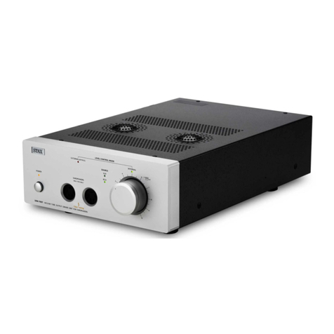
STAX SRM-T8000 User manual

RISK OF ELECTRIC SHOCK DO NOT OPEN!
The SRM-T8000 contains high voltage circuitry.
It is dangerous to disassemble or to remodel it. Please observe Don'ts.
This product contains high-voltage circuitry. To avoid dangerous electric shock, do not disassemble or modify the unit.
○
R

1.Safety information (Please read first)
2.Features / Precautions for use
3.Switches and functions -Front panel
4.Terminals and functions -Rear panel
5.Connection example -Standard connection
6.Connection example -When using preamplifier or attenuator
7.Block diagram
8.Troubleshooting
9.Specifications / Care and Cleaning / Accessories
2
3
4
5
6
7
8
9
10
Page
Thank you very much for purchasing the SRM-T8000 driver unit for STAX earspeakers. Please read this manual carefully in order to use the unit safely and to bring
out its maximum performance for many years of listening pleasure. Please be sure to keep this manual along with the warranty card after reading.

● Prior to use - About WARNING/CAUTION marks
Various WARNING and CAUTION marks are used in this manual for safe
usage of the unit. The possible danger or trouble caused by disregarding
the marks and mishandling the unit are classified as follows. Please read
the manual with these WARNING/CAUTION marks in mind.
Disregarding this mark and mishandling the unit
could result in serious injury or death.
Disregarding and mishandling this mark might
result in injury or physical damage.
WARNING
CAUTION
This mark urges user to take precaution (warning included).
Left example shows “electric shock” caution.
This mark tells prohibited actions.
Left example shows “disassembly-forbidden”.
This mark tells actions you must take without fail.
Left example shows “pull out plug from wall socket”.
Do not put this product on the following places. Otherwise, it may
cause injury or unit failure.
●Places sensitive to vibration or shock, slanted or exposed to
direct sunlight.
●Places with much moisture, humidity and dust.
●Places where temperature differs intensely or near heating ap-
pliance (stove, heater, etc.).
●Do not put earspeaker or any other object on the unit. It may
cover the venting holes and cause heat generation resulting in
unit failure.
●Dropping or giving a shock should be avoided. It becomes the
cause of failure.
●Don't raise volume too much. Listening with large volume could
lead to hearing damage. Listening with moderate volume is rec-
ommended both for your ear and for the unit.
●In case smoke comes out or unusual smell or sound is perceived,
stop using and shut off the power immediately, and then pull out
mains plug from wall socket.
Further using the unit involves the risk of a fire or electric shock,
etc. It is dangerous for a customer to repair the unit. Please
contact your audio shop or the service division of our company.
●Do not remove the bottom plate or the top cover.
●Do not attempt disassembly or modification.
WARNING:
CAUTION:
●Do not pull out or insert mains or earspeaker plug with wet hand
to avoid electric shock.
●Do not use any other mains voltage than indicated.
●Do not bend, twist or pull the power cable by force, nor modify it.
●Do not cover the heat dissipation holes on the top panel and
side panels.
●Do not put metal, liquid or other object into the unit.
●Do not touch the output terminal for earspeaker.
WARNING:
2

●There are high-voltage dangerous sections inside the unit. Do not remove
the top cover or the bottom plate, and avoid using the unit in humid or
dusty places.
●Since the driver unit generates heat, do not cover the venting holes on the
top, side and bottom plates. Put it in an airy place if possible, and when
installing it in a rack etc., keep 5cm or more opening above the upper and
side surface of the unit. Do not use the unit with side panel down.
●Since the degree of adhesion of foot is very high, be careful when moving
the unit.
●Take care when "LEVEL CONTROL" is in "EXTERNAL" position, because
in this position the volume of this unit is bypassed and the volume is not
controlled.
●Since large volume may come out, do not switch "LEVEL CONTROL" to
"EXTERNAL" when wearing your earspeaker.
●When the option card is not equipped, do not remove the cover of the op-
tional slot. Using the unit without the slot cover may cause failure of the
unit.
●Noise such as hum may come out when SOURCE is switched to LINE4
with no option card equipped. This is normal and not a failure.
●The SRM-T8000 is an exclusive driver unit (power amplifier) with 4-input
selector developed in order to ideally drive STAX electrostatic earspeakers.
●The unit incorporates a high-quality double-axis 4-gang volume controller
along with XLR connectors that can connect to all kinds of analog line-level
output terminals.
●The hybrid amplifier configuration with strictly selected low-noise 6922 dual
triode tube for the first stage and high-current emitter-follower at output
stage brings out the maximum performance of earspeakers. Its natural un-
colored sound has been realized by eliminating the coupling capacitor that
affects sound quality.
●The balanced amplifier configuration with low-noise dual triode tube elimi-
nated transformer or inverting amplifier after the XLR balanced input termi-
nal.
●Non-magnetic chassis construction is employed, and only the carefully se-
lected electronic components free from aged deterioration are used taking
both their sonic quality and performance into consideration.
●The SRM-T8000 is equipped with “direct mode” function, enabling it to con-
nect to preamplifier output terminal or to use your favorite attenuator. Also,
two RCA inputs and XLR balanced input can bypass the incorporated vol-
ume controller ( Line 4 input does not have this function).
●Optional extension slot (LINE4) is provided for future use. Refer to the in-
struction manual of this optional card.
●The foot rubber of the SRM-T8000 features fire-resistant ultra-hard high-
grip type and vibration-proof properties. So the unit hardly slides when
placed on a table etc. Please lift it up when you move it.
3

LEVEL
5
0
1
3
4 6
7
9
10
2 8
L R
(INTERNAL)
LEVEL CONTROL
INTERNAL MUTE EXTERNAL
(BYPASS)
LINE1
LINE2 LINE3
LINE4
SOURCE
POWER EARSPEAKERS
PRO-TYPE ONLY
SRM-T8000 VACUUM TUBE INPUT DRIVER UNIT FOR EARSPEAKERS
① ② ③ ④ ⑤ ⑥
②Power switch: pushing in the switch turns the unit on, and
pushing it out turns the unit off.
③Sockets for PRO Type earspeaker: insert 5-pin type
earspeaker plug.
④Volume knob: double-axis structure enables to turn left
and right channel simultaneously. In case right-and-left
channel volume is unbalanced, adjust the volume by inde-
pendently turning the separate volume knobs. The front
side is L-CH and the back side is R-CH.
※We recommend to return volume knob to "0 " when you
turn on or off the unit.
INTERNAL MUTE EXTERNAL
(BYPASS)
LEVEL CONTROL
INTERNAL MUTE EXTERNAL
(BYPASS)
LEVEL CONTROL
INTERNAL MUTE EXTERNAL
(BYPASS)
LEVEL CONTROL
⑤LEVEL CONTROL: volume control operation can be switched either to
the internal volume of the unit, or to the external volume using attenuator
or preamplifier.
1. INTERNAL: Green LED lights up and level can be controlled by inter-
nal volume.
2. MUTE: Green/Red LED blinks and mutes sound in order to urge you
to pay attention before using external volume.
3. EXTERNAL: Red LED lights up and level can be controlled by pream-
plifier or external volume.
When power on and off:
It is recommendable to turn down the volume control
knob to “0” or to set the “LEVEL CONTROL” to “MUTE”.
①Power indicator LED: this blinks for about 1 minute
after powered on and lights up when the tube heater is
warmed up. (Even when the unit is turned on right af-
ter it was turned off, the power indicator blinks again
for about 1 minute.)
Please do not block up the vent of top-cover and both side.
Please do not put a thing on a ventilation hole.
⑥SOURCE: input selector.
1. LINE1/LINE2: selects RCA plug input. Use RCA pin cable provided or
your favorite one.
2. LINE3: selects XLR balance cable input. Polarity is 1-SHIELD 2-HOT 3
-COLD. When connecting equipment with 3-HOT, use polarity
conversion adaptor or conversion cable.
3. LINE4: can be selected only when option card is used.
Factory default “MUTE” position Direct input
GREEN
LED
Lights
GREEN
LED
Blinks
RED LED
Blinks
Top cover Air vent
4

④LINE2: RCA input terminal.
⑤LINE1: RCA input terminal.
Both LINE1 and LINE2 connect to audio equipment with RCA output (CD
player, etc.) or to REC OUT terminal of amplifiers.
⑥PARALLEL OUT: RCA output terminal. PARALLEL OUT terminal directly
outputs signals connected to LINE1. It can be used for connection to an-
other driver unit or to the amplifier to drive loudspeaker. Remove the ca-
ble when equipment connected to PARALLEL OUT is not used.
※On rare occasions, signals from source equipment's are distorted when
the equipment connected to the "PARALLEL OUT" terminal is powered
off. In this case, turn on the connected equipment or remove the cable
from "PARALLEL OUT" terminal.
When adding another SRM-series driver unit using "PARALLEL OUT"
terminal, the power ON/OFF of the added driver unit does not affect
sound if its volume is set to zero.
① ② ③ ④ ⑤
VACUUM TUBE INPUT
DRIVER UNIT FOR EARSPEAKERS
SRM-T8000 DO NOT OPEN
RISK OF ELECTRIC SH OCK
CAUTION !
PARALLEL OUT
LINE1 LINE2
LINE4
LINE3
L
L
R
R
R L
XLR INPUT
STAX LTD. MADE IN JAPAN SERIAL No.
GND
50/60Hz 95W
PUSH PUSH
①
③
②
HOT
SHIELD
COLD
⑥ ⑦ ⑧ ⑨
①XLR polarity indication:
XLR balance input polarity is 1-SHIELD, 2-HOT, 3-COLD.
When connecting equipment with 3-HOT, use polarity con-
version adaptor or conversion cable.
②LINE3: XLR input terminals for equipment provided with
XLR balance output.
③LINE4: optional slot with cover.
When option card is not equipped, do not remove the
cover. Refer to the instruction manual of this option card.
⑦GND: ground terminal.
In case of hum noise connect this terminal to the ground terminal or to
metal part (screw, etc.) of other equipment. Use any available cord for
this purpose.
⑧AC inlet: insert supplied power cable.
⑨Foot: Since the degree of adhesion of the foot is very high, be careful
when moving the unit. Lift it up when you move the unit.
⑩Voltage indication:depending on your country’s voltage.
5
⑩

- Standard connection
Factory default
LOUD SPEAKER
●Usage example of PARALLEL OUT:
① When adding another SRM-series driver unit
② When also using loudspeaker:
Connect PARALLEL OUT to AUX input terminal of an amplifier.
Adjust the volume controller of amplifier.
When adding another SRM-series
driver unit
LINE outputs of personal computer, digital audio, etc.
LINE3: XLR connection
Use XLR cable
When using a loudspeaker in combination:
Connect to the pre / pre-main amplifier from the parallel out terminal.
PRE-MAIN AMP.
MAIN AMP with Volume control
● Other connection than shown below: when connecting to source equipment with mini stereo jack.
The jack is connectable using a commercially available stereo mini plug / RCA plug conversion cable or a conversion plug.
First set the volume of source equipment to the usual headphone listening level, and then adjust the volume of the driver unit.
When connecting source equipment directly to LINE1 or LINE2 input:
Connect REC OUT terminal of your amplifier to LINE1 or LINE2.
Connect REC OUT terminal of your amplifier to LINE1 or LINE2.
VACUUM TUBE INPUT
DRIVER UNIT FOR EARSPEAKERS
SRM-T8000 DO NOT OPEN
RISK OF ELECTRIC SH OCK
CAUTION !
PARALLEL OUT
LINE1 LINE2
LINE4
LINE3
L
L
R
R
R L
XLR INPUT
STAX LTD. MADE IN JAPAN SERIAL No.
GND
50/60Hz 95W
PUSH PUSH
①
③
②
HOT
SHIELD
COLD
-6-
INTERNAL MUTE EXTERNAL
(BYPASS)
LEVEL CONTROL
GREEN
LED
Lights
LINE output equipments such as DVD, SACD/CD/BS/TAPE/
VIDEO, etc.
6
Before connecting, make sure that "Power switch" is off.

INTERNAL MUTE EXTERNAL
(BYPASS)
LEVEL CONTROL
1. When using volume controller of amplifier or attenuator, connect to
either one of RCA (LINE1, LINE2) or XLR
(LINE3). Use XLR cable to connect to LINE3.
2. In this mode do not connect any source equipment with no volume
control, otherwise sound at full volume comes out when you switch
over carelessly.
3. Select SOURCE according to connected input.
Page 4 “Switches and functions Front panel ⑥”
Set “LEVEL CONTROL” knob to “EXTERNAL”.
When using preamplifier or attenuator
LINE output equipments such as DVD, SACD/CD/BS/TAPE/
VIDEO, etc.
Connect the driver unit to PRE OUT terminal of amplifier or attenuator.
Pre- or Integrated amplifier or attenuator
RED LED
Lights
LINE outputs of personal computer, digital audio, etc.
AUX in etc. OUT PUT
Direct input
7
Before connecting, make sure that "Power switch" is off.
VACUUM TUBE INPUT
DRIVER UNIT FOR EARSPEAKERS
SRM-T8000 DO NOT OPEN
RISK OF ELECTRIC SH OCK
CAUTION !
PARALLEL OUT
LINE1 LINE2
LINE4
LINE3
L
L
R
R
R L
XLR INPUT
STAX LTD. MADE IN JAPAN SERIAL No.
GND
50/60Hz 95W
PUSH PUSH
①
③
②
HOT
SHIELD
COLD

LEVEL CONTROL
INT.
INT.
EXT.
EXT.
Double-axis 4-gang
volume controller
INTERNAL MUTE EXTERNAL
(BYPASS)
LEVEL CONTROL
Toroidal transformer
POWER SUPPLY for MAIN PCB, CONTROL-PCB and OPTION SLOT
BIAS
6922
Double triode
High-current emitter follower output stage
PARALLEL OUT
LINE 1:RCA
LINE 3:XLR
LINE 2:RCA
LINE 4 OPTION SLOT
L-CH
R-CH
●
●
●
●
●
Output terminals
●
●
●
●
●
Input selector
GREEN
LED
Lights
8
“LEVEL CONTROL” is in the position for using integrated volume.

When you replace the vacuum tube of drive unit, be sure to ask the pur-
chased store or distributor. Disqualified vacuum tube may sometimes
cause breakdown.
No Sound
● Is the plug of Power cable inserted into the wall socket ?
● Is the power switch on ?
●Does LED on the front panel light up ?
●See that “LEVEL CONTROL” is not in “MUTE” position.
●Check that nothing is wrong with connecting cable..
●When connected to pre- or integrated amplifier, check that the amplifier
selector is set to connected source..
Sound is distorted
●Is supply voltage in stipulated range ?
Turning up the volume too much distorts the sound. Listen with moder-
ate volume.
●See that “LEVEL CONTROL” is not in “EXTERNAL” position. Excessive
input level can distort the sound.
●When the preamplifier (integrated amplifier) connected to the
“PARALLEL OUT” is powered off, it is possible that the sound is distort-
ed because of the lowered impedance. In this case, simply disconnect
the cable. The SRM-T8000 does not affect other connected equipment
even when powered off.
Unbalanced sound between right and left channel
●Are input signals all right ?
●Level difference between channels can be corrected by adjusting double
-axis volume knobs independently.
●When raising volume slowly from zero, it sometimes happens that
sound does not start to come out at the same time from left and right
channels. This is normal and not a failure.
●Volume cannot be adjusted ? See that “LEVEL CONTROL” is not in
“EXTERNAL” position. Set it to “INTERNAL” position.
Hum noise is heard
●Are input terminals connected correctly ? If the ground side of cable is
floated or in poor contact, hum noise may come out.
● In case of buzzing hum noise connect GND terminal to the ground ter-
minal or to metal part of other equipment.
● Connecting GND terminal to window aluminum sash is also effective.
●Is there any poor contact ?
●Is supply voltage in stipulated range ?
●Because of the non-magnetic aluminum chassis hum noise can be in-
duced through connected equipment's. If equipment's with large-sized
transformer or microwave oven etc. are located near driver unit, keep
them away from the unit.
If you have other problems than described above, please contact your
dealer or our distributor in your country.
9

●Pull out power cable from wall socket and wipe it with dry soft cloth.
When very dirty, wipe off dirt with wet cloth and then again with dry cloth.
●Do not use benzine, thinner or alcohol since paint, printing, etc. may
come off. Before using chemical dust cloth, check its attached explana-
tion if it is usable for audio equipment.
● Frequency response: 1Hz - 115kHz +0, -3dB
● Rated input level: 100mV (at 100V output)
● Maximum input level: 30Vrms. (at minimum volume)
● Gain: 60dB (x 1000)
● Harmonic distortion: 0.01% or less (1kHz)
● Input impedance: 50kΩ (RCA input), 50kΩx 2 (XLR input)
● Maximum output voltage: 470Vrms (1330Vp-p) / 1kHz
● Bias voltage: 580V DC
● Mains voltage: AC120V/AC220/AC230/AC240, 50/60Hz
(depending on your country’s voltage)
● Power consumption: 95W/Max. 58W (without optional slot)
● Operating temperature: 0 to 35 degrees C (less than 90% humidity,
non condensing)
● Dimension: 320 (W) x103 (H) x395 (D) mm (maximum protruding por-
tion included)
● Weight: 7.3kg
● Others: equipped with PARALLEL OUT, optional slot and volume by-
pass function and mute function.
※Specifications and appearance are subject to change without notice for
improvement.
※This product is adjusted to mains voltage depending on each country.
Power cable ・・・・・・・・・・・・・・・・・・・・・・・・・・・・1
RCA cable ・・・・・・・・・・・・・・・・・・・・・・・・・・・・・・1
Owner’s manual ・・・・・・・・・・・・・・・・・・・・・・・・・1
10

Printed in Japan 2017-05 MP STAX
C
STAX LIMITED Tel: +81-49-293-1891 Fax: +81-49-293-1892 URL:www.stax.co.jp
3798-1 Shimonanbata, Fujimi-shi, Saitama-ken, Japan 〒354-0004
○
R
Table of contents
Other STAX Amplifier manuals
